Volume 6, Number 4, December, 1998 - Noise News International
Volume 6, Number 4, December, 1998 - Noise News International
Volume 6, Number 4, December, 1998 - Noise News International

You also want an ePaper? Increase the reach of your titles
YUMPU automatically turns print PDFs into web optimized ePapers that Google loves.
(a)<br />
M 4<br />
6:~f=========::::CI~<br />
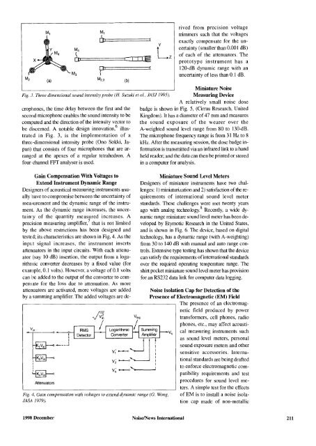
Fig. 3. Three dimensional sound intensity probe (H. Suzuki et al., lASl 1995).<br />
(b)<br />
crophones, the time delay between the first and the<br />
second microphone enables the sound intensity to be<br />
computed and the direction of the intensity vector to<br />
be discerned. A notable design innovation.i' illustrated<br />
in Fig. 3, is the implementation of a<br />
three-dimensional intensity probe (Ono Sokki, Japan)<br />
that consists of four microphones that are arranged<br />
at the apexes of a regular tetrahedron. A<br />
four- channel FFT analyser is used.<br />
Gain Compensation WithVoltages to<br />
ExtendInstrument Dynamic Range<br />
Designers of acoustical measuring instruments usually<br />
[lave to compromise between the uncertainty of<br />
measurement and the dynamic range of the instrument.<br />
As the dynamic range increases, the uncertainry<br />
of the quantity measured increases. A<br />
precision measuring amplifier' that is not limited<br />
by the above restrictions has been designed and<br />
tested; its characteristics are shown in Fig. 4. As the<br />
input signal increases, the instrument inserts<br />
attenuators in the input circuits. With each attenuator<br />
(say 10 dB) insertion, the output from a logarithmic<br />
converter decreases by a fixed value (for<br />
example, 0.1 volts). However, a voltage of 0.1 volts<br />
can he added to the output of the converter to compensate<br />
for the loss due to attenuation. As more<br />
attenuators are activated, more voltages are added<br />
by a summing amplifier. The added voltages are de-<br />
~'T-lin,--__o .....---9--1<br />
I<br />
I<br />
I I<br />
~<br />
Atlenuators<br />
I<br />
I<br />
I<br />
--_ I<br />
..-"<br />
v; ....-...<br />
v: ...-.0'-. ....---<br />
Fig. 4. Gain compensation with voltages to extend dynamic range (G. Wong,<br />
lASA 1979).<br />
rived from precision voltage<br />
trimmers such that the voltages<br />
exactly compensate for the uncertainty<br />
(smaller than 0.001 dB)<br />
of each of the attenuators. The<br />
prototype instrument has a<br />
l20-dB dynamic range with an<br />
uncertainty of less than 0.1 dB.<br />
Miniature <strong>Noise</strong><br />
Measuring Device<br />
A relatively small noise dose<br />
badge is shown in Fig. 5, (Cirrus Research, United<br />
Kingdom). It has a diameter of 47 mm and measures<br />
the sound exposure of the wearer over the<br />
A-weighted sound level range from 80 to l30-dB.<br />
The microphone frequency range is from 31 Hz to 8<br />
kHz. After the measuring session, the dose badge information<br />
is transmitted via an infrared link to a hand<br />
held reader; and the data can then be printed or stored<br />
in a computer for analysis.<br />
Miniature SoundLevelMeters<br />
Designers of miniature instruments have two challenges:<br />
1) miniaturization and 2) satisfactionof the requirements<br />
of international sound level meter<br />
standards. These challenges were met twenty years<br />
ago with analog tecbnology'' Recently, a wide dynamic<br />
range miniature sound level meter has been developed<br />
by Etymotic Research in the United States,<br />
and is shown in Fig. 6. The device, based on digital<br />
technology, has a dynamic range (with A-weighting)<br />
from 30 to 140 dB with manual and auto range controls.<br />
Extensive type testing has shown that the device<br />
can satisfy the requirements of international standards<br />
over the required operating temperature range. The<br />
shirt pocket miniature sound level meter has provision<br />
for an RS232 data link for computer data logging.<br />
<strong>Noise</strong>IsolationCapfor Detection of the<br />
Presence of Electromagnetic (EM) Field<br />
The presence of an electromagnetic<br />
field produced by power<br />
transformers, cell phones, radio<br />
phones, etc., may affect acousti-<br />
V s<br />
cal measuring instruments such<br />
as sound level meters, personal<br />
sound exposure meters and other<br />
sensitive accessories. <strong>International</strong><br />
standards are being drafted<br />
to enforce electromagnetic compatibility<br />
requirements and test<br />
procedures for sound level meters.<br />
A simple test for the effects<br />
of EM is to install a noise isolation<br />
cap made of non-metallic<br />
<strong>1998</strong> <strong>December</strong> <strong>Noise</strong>l<strong>News</strong> <strong>International</strong> 211