001 Resp AAN - Garney Construction
001 Resp AAN - Garney Construction
001 Resp AAN - Garney Construction

You also want an ePaper? Increase the reach of your titles
YUMPU automatically turns print PDFs into web optimized ePapers that Google loves.
Marcus Grace<br />
From:<br />
Sent:<br />
To:<br />
Subject:<br />
Attachments:<br />
Marcus Grace<br />
Wednesday, December 07, 2011 8:27 AM<br />
Chris Browder; Christopher Burress<br />
FW: Pump Can Review<br />
44 42 56 02 Suction Barrel Submittal (2) (ES 11-30-2011).pdf<br />
Chris’s,<br />
Please find Pump Barrel Submittal comments attached. Please revise submittal per CMAR and Engineer comments.<br />
Please begin fabrication of Pump Barrels making sure all CMAR and Engineer submittal comments are taken into account<br />
during fabrication.<br />
Marcus Grace<br />
GARNEY CONSTRUCTION Advancing Water<br />
PH: 816.536.6485 FAX: 816.278.5931<br />
ADDRESS: 6050 IH 35 South, San Marcos, TX 78666 GARNEY.COM<br />
From: Nick Lester [mailto:ncl@freese.com]<br />
Sent: Wednesday, December 07, 2011 5:39 AM<br />
To: Marcus Grace; Mike Gardner<br />
Cc: James Johnson; Bryan Jann<br />
Subject: Pump Can Review<br />
Marcus,<br />
Attached is the pump can review comments. Please contact me if you have any questions. Please post the submittal on<br />
FN Manager Pro and I will post the comments for accounting purposes.<br />
Thanks,<br />
Nick<br />
Nicholas Lester, P.E.<br />
Associate<br />
Freese and Nichols, Inc.<br />
4055 International Plaza<br />
Suite 200<br />
Fort Worth, Texas 76109<br />
Phone: (817) 735‐7393<br />
Fax: (817) 735‐7420<br />
Mobile: (817) 680‐9993<br />
Email: NCL@freese.com<br />
Please consider the environment before printing this message.<br />
This electronic mail message is intended exclusively for the individual or entity to which it is addressed. This message, together with any attachment, may contain<br />
the sender's organization's confidential and privileged information. The recipient is hereby notified to treat the information as confidential and privileged and to not<br />
disclose or use the information except as authorized by sender's organization. Any unauthorized review, printing, retention, copying, disclosure, distribution,<br />
retransmission, dissemination or other use of, or taking of any action in reliance upon, this information by persons or entities other than the intended recipient is<br />
1
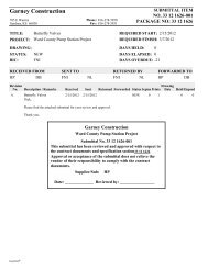
<strong>Garney</strong> <strong>Construction</strong>, Inc.<br />
785 E Warren<br />
Gardner, KS 66030<br />
Phone: 816-278-5950<br />
Fax: 816-278-5931<br />
TRANSMITTAL<br />
No. 0<strong>001</strong>2<br />
PROJECT:<br />
TO:<br />
Ward County Pump Station Project<br />
Smith Pump Company, Inc.<br />
301 M&B Industrial<br />
Waco, TX 76710<br />
DATE: 12/7/2011<br />
JOB: 4383<br />
REF: Returned Submittals<br />
ATTN:<br />
WE ARE SENDING:<br />
SUBMITTED FOR:<br />
ACTION TAKEN:<br />
Shop Drawings Approval Approved as Submitted<br />
Letter Your Use Approved as Noted<br />
Prints As Requested Returned After Loan<br />
Change Order Review and Comment Resubmit<br />
Plans<br />
Samples<br />
Specifications<br />
Chris Browder<br />
Other: Returned Submittal<br />
ITEM NO. COPIES<br />
SENT VIA:<br />
Attached<br />
Separate Cover Via:<br />
Mail<br />
DATE ITEM NUMBER REV. NO. DESCRIPTION<br />
Submit<br />
Returned<br />
Returned for Corrections<br />
Due Date:<br />
STATUS<br />
1 12/7/2011 SUT 44 42 56.-<strong>001</strong> <strong>001</strong> Dwg: Title: Verticle Turbine Pumping Unit <strong>AAN</strong><br />
Cans Desc: 44 42 56-<strong>001</strong>, Pump Cans<br />
Remarks:<br />
Please Fabricate Pump Barrels per Returnded Submittal Comments.<br />
CC: Share Point<br />
Signed:<br />
Eric Shaffer<br />
Expedition ®
<strong>Garney</strong> <strong>Construction</strong><br />
785 E Warren<br />
Gardner, KS 66030<br />
Phone: 816-278-5950<br />
Fax: 816-278-5931<br />
SUBMITTAL ITEM<br />
NO. 44 42 56.02 <strong>001</strong><br />
PACKAGE NO: 44 42 56.<br />
TITLE:<br />
PROJECT:<br />
DRAWING:<br />
STATUS:<br />
BIC:<br />
Vertical Turbine Pumping Unit Cans<br />
Ward County Pump Station Project<br />
<strong>AAN</strong><br />
REQUIRED START:<br />
REQUIRED FINISH:<br />
DAYS HELD: 0<br />
DAYS ELAPSED: 9<br />
DAYS OVERDUE: 0<br />
RECEIVED FROM<br />
SMITH CB<br />
SENT TO<br />
FNI<br />
NL<br />
RETURNED BY<br />
FNI NL<br />
FORWARDED TO<br />
SMITH CB<br />
Revision<br />
No.<br />
Description / Remarks<br />
Received<br />
Sent<br />
Drawing<br />
Returned Forwarded Status Sepias Prints Date HeldElapsed<br />
A Vertical Turbine Pump Cans 11/28/2011 12/1/2011 12/7/2011 12/7/2011 <strong>AAN</strong> 0 1 -79 9<br />
To whom it may concern:<br />
This submittal contains information pertaining to the pump cans as listed in specification section 44 42 56.02, Vertical<br />
Turbine Pumping Units.<br />
Please see contractors review comments contained in this submittal.<br />
If you have any questions or need any additional information please contact Eric Shaffer at (636) 577-7524 or e-mail me at<br />
eshaffer@garney.com.<br />
Thanks<br />
Freese and Nichols <strong>Resp</strong>onse:<br />
Approved as Noted<br />
See engineer's comments in the submittal response.<br />
<strong>Garney</strong> <strong>Construction</strong><br />
Ward County Pump Station Project<br />
Submittal No. 44 42 56.02 <strong>001</strong><br />
This submittal has been reviewed and approved with respect to<br />
the contract documents and specification section44 42 56.<br />
Approval or acceptance of the submittal does not relieve the<br />
vendor of their responsibility to comply with the contract<br />
documents.<br />
Supplier/Sub:<br />
SMITH<br />
Date: ______________ Reviewed by: _________________<br />
Expedition ®
Project No:<br />
Project:<br />
Client:<br />
Contractor:<br />
CMD11269A<br />
Ward County Transmission System - Pumps<br />
Colorado River Municipal Water District<br />
<strong>Garney</strong><br />
Shop Drawing #<strong>001</strong><br />
Vertical Turbine Pumping Unit Cans<br />
SUBMITTAL INFORMATION<br />
SUBMITTAL<br />
TYPE:<br />
SUBMITTAL #: CONTRACTOR REF #: SPEC SECTION: PLAN SHEET: SUBMITTAL STATUS:<br />
Shop Drawing <strong>001</strong><br />
Approved As Noted, Final<br />
Distribution<br />
SUBMITTAL<br />
DESCRIPTION:<br />
Vertical Turbine Pumping Unit Cans<br />
UPLOAD SUPPORTING DOCUMENTS<br />
44 42 56 02 Suction Barrel Submittal (2)( ES 11-30-2011).pdf 12/7/2011 10:28 AM Debby Greer<br />
CONTRACTOR CERTIFICATION<br />
CONTRACTOR COMMENTS:<br />
see attached emailed to NCL 12/01/2011<br />
HOW WILL THE COPIES BE SUBMITTED:<br />
Email<br />
NUMBER OF COPIES SUBMITTED: 1<br />
This shop drawing has been reviewed by the Contractor and certified to be in strict conformance with the Contract Documents as modified by addenda, field orders, and<br />
change orders. Deviations can only be approved by field order or change order. Approval is only for conformance with the design concept of the project and compliance with<br />
the intent of the information given in the Contract Documents. Contractor is responsible for dimensions to be confirmed and correlated at the job site; for information that<br />
pertains solely to the fabrication processes or to techniques of construction; and for the work of all trades.<br />
SUBMITTED BY: Debby Greer<br />
DATE: 12/7/2011 10:28 AM<br />
REVIEWER COMMENTS<br />
REVIEWER NAME: REVIEWER EMAIL: COMPANY / ORGANIZATION DATE SENT: DATE<br />
COMPLETED:<br />
Debby Greer<br />
dag@freese.com<br />
Freese & Nichols, Inc.<br />
12/7/2011<br />
12/7/2011<br />
REVIEWER COMMENTS:<br />
Per NCL: Approved As Noted, See attached marked up comments.<br />
UPLOAD SUPPORTING REVIEW DOCUMENTS<br />
44 42 56 02 Suction Barrel Submittal (2) (ES 11-30-2011).pdf Remove 12/7/2011 10:35 AM Debby Greer<br />
DISPLAY ROUTING SLIP gfedc<br />
Current Workflow Step: DCS Admin: Debby Greer Workflow Initiator: Debby Greer<br />
(Click on the Names above to Email User)<br />
FNI Forms v1.04
SUCTION BARREL<br />
SUBMITTAL DOCUMENTS<br />
for<br />
CRMWD<br />
Colorado River Municipal Water District<br />
Ward County Water Supply Expansion Project –<br />
Pump Station, Bid Package # 1 – Pumps and<br />
Motors<br />
<strong>Garney</strong> Companies<br />
44 42 56.02<br />
Vertical Turbine Pumping Units<br />
Suction Barrel<br />
For questions please contact…<br />
Smith Pump Company, Inc.<br />
301 M&B Industrial<br />
Waco, Texas 76712<br />
Attention:<br />
Matt Ramburger<br />
Phone: 254.776.0377<br />
Facsimile: 254.399.8274<br />
E-mail: mattr@smithpump.com<br />
SMITH PUMP COMPANY, INC, Page 1 of 1<br />
C:\Documents and Settings\Mattr\My Documents\CRMWD Ward County\Barrel Submittal Cover Page.docx<br />
22 November 2011
INDEX<br />
for<br />
<strong>Garney</strong> Companies<br />
on the<br />
CRMWD<br />
Colorado River Municipal Water District<br />
on the<br />
Ward County Water Supply Expansion Project – Pump Station,<br />
Bid Package # 1 – Pumps & Motors<br />
ITEM PAGES ----------------- DESCRIPTION --------------------<br />
1 1 Submittal Cover page<br />
2 2 Index<br />
3 3 TAB: General<br />
… Warranty<br />
… Contractor’s Check List to Obtain a Warranty<br />
… Comments and Clarifications<br />
4 TAB: OEM Submittal<br />
5 8 TAB: TPS Barrel Submittal<br />
…….. Scope of Supply<br />
……… Suction Barrel Overall Drawing<br />
……… Top Flange to Pipe Detail<br />
……… Hydro-cone Detail<br />
……… O-ring Detail<br />
……… Sleeve Anchors<br />
……… Tnemec Series 140 Coating Spec<br />
6 8 TAB: OPS Barrel Submittal<br />
……. Scope of Supply<br />
……… Suction Barrel Overall Drawing<br />
……… Top Flange to Pipe Detail<br />
……… Hydro-cone Detail<br />
……… O-ring Detail<br />
………. Sleeve Anchors<br />
……… Tnemec Series 140 Coating Spec<br />
SMITH PUMP COMPANY, INC. Page 1 of 2<br />
file: C:\Documents and Settings\Mattr\My Documents\CRMWD Ward County\Ward County barrel Index.doc<br />
REVISION: Original 22 November 2011
7 4 TAB: Suction Barrel Installation Recommendations<br />
……… Barrel Flange Welding and Leveling Procedure<br />
……… Procedure for Checking Level<br />
……… Grouting Recommendations<br />
SMITH PUMP COMPANY, INC. Page 2 of 2<br />
file: C:\Documents and Settings\Mattr\My Documents\CRMWD Ward County\Ward County barrel Index.doc<br />
REVISION: Original 22 November 2011
GENERAL
SMITH PUMP COMPANY, INC.<br />
WARRANTY<br />
GARNEY COMPANIES Page 1 of 1<br />
COLORADO RIVER MUNICIPAL WATER DISTRICT<br />
WARD COUNTY WATER SUPPLY PROJECT<br />
SMITH PUMP COMPANY, INC. does hereby warrant and guarantee all equipment furnished by<br />
us to be free from defect in materials or workmanship for a period of twenty-four (24) months<br />
after date of start up or initial use or thirty (30) months after date of delivery, whichever comes<br />
first. Additional manufacturers’ warranties may apply. The contractor must notify Smith Pump<br />
Company in writing at the start of the warranty period<br />
This guarantee is FOB nearest Smith Pump Company facility. Smith Pump Company will not<br />
be responsible for any removal or reinstallation charges, transportation charges, etc. in cases<br />
where equipment has failed under these warranty conditions. The use of any equipment for<br />
other than its intended purpose will void the warranty.<br />
Requests for start-up must occur seven (7) days prior to requested schedule date.<br />
The equipment supplied on this project has a warranty requirement that qualified Smith<br />
Pump Company personnel be present during the initial equipment start-up and<br />
commissioning. Failure to request the presence of qualified personnel may void warranty.<br />
Modifications to the equipment without written approval from Smith Pump Company will<br />
void the warranty.<br />
It is the responsibility of the Contractor and Owner to properly store and maintain any and<br />
all of the furnished equipment from the time it is delivered to the jobsite through the end<br />
on the warranty period. Failure to do so may void warranty.<br />
FOR ASSISTANCE ON WARRANTY ISSUES OR OTHER ISSUES CONTACT:<br />
SMITH PUMP COMPANY, INC., WACO, TEXAS, 800-299-8909
CONTRACTOR’S CHECK LIST TO OBTAIN A WARRANTY<br />
<strong>Garney</strong> Companies<br />
CRMWD<br />
Colorado River Municipal Water District<br />
Ward County Water Supply Expansion Project<br />
Pump Station, Bid Package # 1 Pumps & Motors<br />
44 42 56.02<br />
Vertical Turbine Pumping Units<br />
There are numerous inspection points once equipment begins to arrive at the jobsite.<br />
This document provides documentation that each point of inspection has occurred, and<br />
was acceptable.<br />
At the end of the project, the Contractor will need Smith Pump signatures at each<br />
inspection point for all suction barrels.<br />
Inspection Points<br />
1. Pre-back fill barrel plumb.<br />
2. Pre-weld barrel top flange level.<br />
3. Post-weld barrel top flange level.<br />
4. Pre-grout barrel top flange level.<br />
5. Instruct Contractor on proper grouting (see back of this submittal for instructions)<br />
Transmission Pump Station<br />
Inspection Barrel<br />
Point Date Signature Date Signature Date Signature<br />
1 ____ _________ ____ _________ _____ _________<br />
2 ____ _________ ____ _________ _____ _________<br />
3 ____ _________ ____ _________ _____ _________<br />
4 ____ _________ ____ _________ _____ _________<br />
5 ____ _________ ____ _________ _____ _________<br />
Odessa Pump Station<br />
Inspection Barrel<br />
Point Date Signature Date Signature Date Signature<br />
1 ____ _________ ____ _________ _____ _________<br />
2 ____ _________ ____ _________ _____ _________<br />
3 ____ _________ ____ _________ _____ _________<br />
4 ____ _________ ____ _________ _____ _________<br />
5 ____ _________ ____ _________ _____ _________
<strong>Garney</strong> Companies<br />
SUBMITTAL<br />
COMMENTS AND CLARIFICATIONS<br />
CRMWD<br />
Colorado River Municipal Water District<br />
Ward County Water Supply Expansion Project<br />
Pump Station, Bid Package # 1 – Pumps and Motors<br />
1- Transmission Pump Station<br />
Suction Barrels will be fabricated from 42” O.D. x 1/2” wall<br />
pipe body with a 30” I.D. x 1/2 wall rolled pipe inlet.<br />
2- Odessa Pump Station<br />
Suction Barrels will be fabricated from 48” O.D. x 1/2” wall<br />
pipe body with a 36” I.D. x 1/2 wall rolled pipe inlet.<br />
3- Contractor to confirm sleeve type anchor bolt dimensions<br />
prior to manufacturing.
OEM SUBMITTAL
SMITH PUMP COMPANY<br />
EQUIPMENT DESCRIPTION<br />
44 42 56.02<br />
VERTICAL TURBINE PUMPING UNITS<br />
TRANSMISSION PUMP STATION SUCTION BARRELS<br />
4- 42” OD X 0.50” WALL X 285” LONG FABRICATED STEEL SUCTION CAN<br />
WITH 36" DIA PLAIN END INLET WITH SPLITTER PLATE.<br />
A) TOP FLANGE ASSEMBLY TACK WELDED TO BARREL AT SHOP<br />
B) TOP FLANGE TO HAVE THREADED BOLT HOLES AND O-RING GROOVE<br />
C) 2-3/4” THICK BOTTOM PLATE<br />
D) 4 – 1” FLATS WELDED TO CAN AS BOTTOM ANCHOR POINTS<br />
E) 3” X 3” ANGLES FOR CONCRETE ENCASEMENT ANCHORS<br />
F) 2- 2” COUPLINGS ARE WELDED ~6” BELOW TOP FLANGE<br />
G) 2 FULL LENGTH FLOW VANES AND 6 FLOW VANES FROM BOTTOM<br />
TO BOTTOM OF INLET.<br />
H) 3 LIFTING LUGS<br />
I) 4 1” diameter x 18” long stainless steel epoxy anchors<br />
(for bottom of barrel)<br />
J) 4 1-1/2” diameter sleeve type anchor bolts (see drawing)<br />
(for at top flange of barrel)<br />
1- ITEM BLASTING AND COATING AS FOLLOWS:<br />
A) GRIT BLAST TO SSPS-SP-10, NEAR WHITE, INSIDE AND OUTSIDE<br />
B) INTERIOR OF SUCTION CANS TO RECEIVE (2) TWO COATS OF TNEMEC<br />
SERIES 140 POT-A-POX (12 MILS MIN DFT. - TOTAL) FINISH COLOR<br />
"TANK WHITE"<br />
C) EXTERIOR OF SUCTION CANS TO RECEIVE (2) TWO COATS OF TNEMEC<br />
SERIES 140 POT-A-POX (12 MILS MIN DFT. - TOTAL) FINISH COLOR<br />
"TANK WHITE"<br />
1- ITEM OF O-RING MATERIAL AS SEAL BETWEEN HEAD AND BARREL<br />
(PROVIDED WITH DISCHARGE HEAD BY FLOWSERVE)<br />
1- ITEM OF TOUCH UP PAINT<br />
1- ITEM DELIVERY TO JOBSITE<br />
1- ITEM OF MILL WRIGHT TO FIELD CHECK LEVELNESS OF TOP FLANGE AND<br />
PLUMBNESS OF BARREL PRIOR TO GROUTING AND BACK FILLING.<br />
NOTES:<br />
1. ITEMS NOT INCLUDED: GROUT, CONCRETE, PIPING, VALVES, FIELD<br />
PAINTING, INSTALLATION, FIELD WELDING AND LEVELING, BLEED-OFF<br />
PIPING, UNLOADING AT JOBSITE.<br />
2. CONTRACTOR / ENGINEER TO VERIFY THE FIELD ELEVATIONS ON<br />
DRAWING.<br />
C:\Documents and Settings\Mattr\My Documents\Submittal Templates\TPS-Barrel Submittal SCope of<br />
Supply Ward County.doc
Pota-Pox Plus<br />
SERIES N140<br />
PRODUCT PROFILE<br />
®<br />
GENERIC DESCRIPTION<br />
COMMON USAGE<br />
COLORS<br />
SPECIAL QUALIFICATIONS<br />
PERFORMANCE CRITERIA<br />
Polyamidoamine Epoxy<br />
Innovative potable water coating which offers high-build edge protection and allows for application<br />
at a wide range of temperatures (down to 35°F or 2°C with 44-700 Accelerator). For use on<br />
the interior and exterior of steel or concrete tanks, reservoirs, pipes, valves, pumps and equipment<br />
in potable water service.<br />
1211 Red Oxide, 1255 Beige, 11WH White, 15BL Tank White, 35GR Black and 39BL Delft Blue.<br />
Note: Epoxies chalk with extended exposure to sunlight. Lack of ventilation, incomplete mixing,<br />
miscatalyzation or the use of heaters that emit carbon dioxide and carbon monoxide during<br />
application and initial stages of curing may cause yellowing to occur.<br />
Certified by NSF International in accordance with ANSI/NSF Std. 61. Ambient air cured Series N140<br />
(with or without 44-700 Epoxy Accelerator) is qualified for use on tanks and reservoirs of 1,000 gallons<br />
(3,785L) capacity or greater, pipes four (4) inches (10 cm) in diameter or greater and valves two (2)<br />
inches (5 cm) in diameter or greater. Conforms to AWWA D 102 Inside Systems No. 1 and No. 2<br />
(with or without 44-700). Conforms to AWWA C 210 (without 44-700). Contact your Tnemec representative<br />
for systems and additional information.<br />
Extensive test data available. Contact your Tnemec representative for specific test results.<br />
Certified to<br />
ANSI/NSF 61<br />
COATING SYSTEM<br />
PRIMERS Self-priming, 20, FC20, 91-H 20, N140F<br />
TOPCOATS Interior: Series N140, N140F. Exterior: Series 27, 66, N69, 73, N140, N140F, 161, 175, 180,<br />
700, 1074, 1075. Refer to COLORS on applicable topcoat data sheets for additional information.<br />
Note: When topcoating with Series 700, an intermediate coat of Series 73 or 1075 is required.<br />
Note: The following maximum recoat times apply when using Endura-Shield topcoats: Series 73,<br />
ninety (90) days; Series 175, 1074 or 1075 sixty (60) days. If these time limits are exceeded, Series<br />
N140 must be uniformly scarified or recoated with itself prior to applying Endura-Shield. When<br />
topcoating with Series 180, the N140 maximum recoat time is 90 days.<br />
SURFACE PREPARATION<br />
STEEL<br />
PRIMED STEEL<br />
CAST/DUCTILE IRON<br />
CONCRETE<br />
ALL SURFACES<br />
Immersion Service: SSPC-SP10/NACE 2 Near-White Blast Cleaning<br />
Non-Immersion Service: SSPC-SP6/NACE 3 Commercial Blast Cleaning<br />
Immersion Service: Scarify the Series N140, 20 or FC20 prime coat surface by blasting with fine<br />
abrasive before topcoating if it has been exterior exposed for 60 days or longer and N140 is the<br />
specified topcoat.<br />
Contact your Tnemec representative or Tnemec Technical Services.<br />
Allow new concrete to cure 28 days. For optimum results and/or immersion service, abrasive blast<br />
referencing SSPC-SP13/NACE 6 Surface Preparation of Concrete and Tnemec’s Surface Preparation<br />
and Application Guide. Fill all holes, pits, voids and cracks with 63-1500 Filler and Surfacer.<br />
Must be clean, dry and free of oil, grease and other contaminants.<br />
TECHNICAL DATA<br />
VOLUME SOLIDS*<br />
RECOMMENDED DFT<br />
67.0 ± 2.0% (mixed—A, B & 44-700 Epoxy Accelerator)<br />
3.0 to 8.0 mils (75 to 205 microns) per coat. Note: Number of coats and thickness requirements will<br />
vary with substrate, application method and exposure. Contact your Tnemec representative.<br />
CURING TIME AT 5 MILS DFT Temperature To Handle To Recoat Immersion<br />
Without 44-700 Accelerator 75°F (24°C) 6 hours 9 hours 7 days<br />
With 44-700 Accelerator 75°F (24°C) 4 hours 5 hours 7 days<br />
65°F (18°C) 7-8 hours 9-11 hours 8 days<br />
55°F (13°C) 12-14 hours 16-20 hours 9-10 days<br />
45°F (7°C) 18-22 hours 28-32 hours 12-13 days<br />
35°F (2°C) 28-32 hours 46-50 hours 16-18 days<br />
Curing time varies with surface temperature, air movement, humidity and film thickness.<br />
Note: For valve applications allow 14 days cure at 75°F (24°C) prior to immersion. For pipe<br />
applications allow 30 days cure at 75°F (24°C) prior to immersion.<br />
VOLATILE ORGANIC Unthinned Thinned 10%<br />
COMPOUNDS* 2.37 lbs/gallon 2.78 lbs/gallon<br />
(284 grams/litre) (333 grams/litre)<br />
THEORETICAL COVERAGE* 1,070 mil sq ft/gal (27.2 m 2 /L at 25 microns). See APPLICATION for coverage rates.<br />
NUMBER OF COMPONENTS Two: Part A and Part B or Three: Part A, Part B and 44-700 Epoxy Accelerator<br />
PACKAGING 5 gallon (18.9L) pails and 1 gallon (3.79L) cans — Order in multiples of 2.<br />
Reference 44-700 Epoxy Accelerator product data sheet for its packaging information.<br />
NET WEIGHT PER GALLON* 12.63 ± 0.25 lbs (5.82 ± .11 kg) (mixed)<br />
Published technical data and instructions are subject to change without notice. The online catalog at www.tnemec.com should be referenced for the most<br />
current technical data and instructions or you may contact your Tnemec representative for current technical data and instructions.<br />
© March 2004, by Tnemec Company, Inc. N140
SERIES N140<br />
Pota-Pox Plus<br />
TECHNICAL DATA continued<br />
STORAGE TEMPERATURE Minimum 20°F (-7°C) Maximum 110°F (43°C)<br />
TEMPERATURE RESISTANCE (Dry) Continuous 250°F (121°C) Intermittent 275°F (135°C)<br />
SHELF LIFE 24 months at recommended storage temperature.<br />
FLASH POINT - SETA Part A: 82°F (28°C) Part B: 80°F (27°C) 44-700: None<br />
HEALTH & SAFETY Paint products contain chemical ingredients which are considered hazardous. Read container label<br />
warning and Material Safety Data Sheet for important health and safety information prior to the use of<br />
this product. Keep out of the reach of children.<br />
APPLICATION<br />
COVERAGE RATES* Primer Intermediate / Topcoat<br />
Dry Mils Wet Mils Sq Ft/Gal Dry Mils Wet Mils Sq Ft/Gal<br />
(Microns) (Microns) (m 2 /Gal) (Microns) (Microns) (m 2 /Gal)<br />
Suggested (1) 4.0 (100) 6.0 (150) 268 (24.9) 5.0 (125) 7.5 (190) 214 (19.9)<br />
Minimum 3.0 (75) 4.5 (115) 357 (33.2) 4.0 (100) 6.0 (150) 268 (24.9)<br />
Maximum 5.0 (125) 7.5 (190) 214 (19.9) 6.0 (150) 9.0 (230) 178 (16.6)<br />
(1) Note: Roller or brush application requires two or more coats to obtain recommended film thickness.<br />
Series N140 can be spray applied to an optional high-build film thickness range of 6.0 to 8.0 dry mils (150<br />
to 205 dry microns) or 8.5 to 11.5 wet mils (215 to 290 wet microns). Allow for overspray and surface<br />
irregularities. Film thickness is rounded to the nearest 0.5 mil or 5 microns. Application of coating below<br />
minimum or above maximum recommended dry film thicknesses may adversely affect coating performance.<br />
MIXING l. Start with equal amounts of both Parts A & B.<br />
2. Using a power mixer, separately stir Parts A & B.<br />
3. (For accelerated version. If not using 44-700, skip to No. 4.)<br />
Add four (4) fluid ounces of 44-700 per gallon of Part A while Part A is under agitation.<br />
4. Add Part A to Part B under agitation, stir until thoroughly mixed.<br />
5. Both components must be above 50°F (10°C) prior to mixing. For application of the unaccelerated<br />
version to surfaces between 50°F to 60°F (10°C to 16°C) or the accelerated version to surfaces between<br />
35°F to 50°F (2°C to 10°C), allow mixed material to stand 30 minutes and restir before using.<br />
6. For optimum application properties, the material temperature should be above 60°F (16°C).<br />
Note: The use of more than the recommended amount of 44-700 will adversely affect performance.<br />
POT LIFE Without 44-700 15 hours at 50°F (10°C) 5 hours at 77°F (25°C) 3 hours at 100°F (38°C)<br />
With 44-700 8 hours at 35°F (2°C) 4 hours at 77°F (25°C) 1 hour at 100°F (38°C)<br />
THINNING Use No. 4 Thinner. For air spray, thin up to 10% or ¾ pint (380 mL) per gallon. For airless spray, roller or<br />
brush, thin up to 5% or ¼ pint (190 mL) per gallon. Caution: Series N140 NSF certification is based on<br />
thinning with No. 4 Thinner. Use of any other thinner voids ANSI/NSF Std. 61 certification.<br />
SURFACE TEMPERATURE Without 44-700 Minimum 50°F (10°C) Maximum 135°F (57°C)<br />
With 44-700 Minimum 35°F (2°C) Maximum 135°F (57°C)<br />
The surface should be dry and at least 5°F (3°C) above the dew point. Coating won’t cure below<br />
minimum surface temperature.<br />
APPLICATION EQUIPMENT<br />
Air Spray<br />
Gun Fluid<br />
Tip<br />
Air Cap Air Hose<br />
ID<br />
Mat’l Hose<br />
ID<br />
Atomizing<br />
Pressure<br />
Pot<br />
Pressure<br />
DeVilbiss E 765 5/16” or 3/8” 3/8” or 1/2” 75-100 psi 10-20 psi<br />
MBC or JGA or 78 (7.9 or 9.5 mm) (9.5 or 12.7 mm) (5.2-6.9 bar) (0.7-1.4 bar)<br />
Low temperatures or longer hoses require higher pot pressure.<br />
Airless Spray<br />
Tip Orifice Atomizing Pressure Mat’l Hose ID Manifold Filter<br />
0.015”-0.019” 1800-3000 psi 1/4” or 3/8” 60 mesh<br />
(380-485 microns) (124-207 bar) (6.4 or 9.5 mm) (250 microns)<br />
Use appropriate tip/atomizing pressure for equipment, applicator technique and weather conditions.<br />
Note: Application over inorganic zinc-rich primers: Apply a wet mist coat and allow tiny bubbles to<br />
form. When bubbles disappear in 1 to 2 minutes, apply a full wet coat at specified mil thickness.<br />
Roller: Roller application optional when environmental restrictions do not allow spraying. Use 3/8” or<br />
1/2” (9.5 mm or 12.7 mm) synthetic nap covers.<br />
Brush: Recommended for small areas only. Use high quality natural or synthetic bristle brushes.<br />
CLEANUP Flush and clean all equipment immediately after use with the recommended thinner or MEK.<br />
*Values may vary with color.<br />
WARRANTY & LIMITATION OF SELLER’S LIABILITY: Tnemec Company, Inc. warrants only that its coatings represented herein meet the formulation standards of Tnemec Company, Inc.<br />
THE WARRANTY DESCRIBED IN THE ABOVE PARAGRAPH SHALL BE IN LIEU OF ANY OTHER WARRANTY, EXPRESSED OR IMPLIED, INCLUDING BUT NOT LIMITED TO, ANY IMPLIED WARRANTY OF MERCHANTABILITY OR FITNESS FOR A<br />
PARTICULAR PURPOSE. THERE ARE NO WARRANTIES THAT EXTEND BEYOND THE DESCRIPTION ON THE FACE HEREOF. The buyer’s sole and exclusive remedy against Tnemec Company, Inc. shall be for replacement of the product in the<br />
event a defective condition of the product should be found to exist and the exclusive remedy shall not have failed its essential purpose as long as Tnemec is willing to provide comparable replacement product to the buyer. NO OTHER<br />
REMEDY (INCLUDING, BUT NOT LIMITED TO, INCIDENTAL OR CONSEQUENTIAL DAMAGES FOR LOST PROFITS, LOST SALES, INJURY TO PERSON OR PROPERTY, ENVIRONMENTAL INJURIES OR ANY OTHER INCIDENTAL OR CONSEQUENTIAL<br />
LOSS) SHALL BE AVAILABLE TO THE BUYER. Technical and application information herein is provided for the purpose of establishing a general profile of the coating and proper coating application procedures. Test performance results<br />
were obtained in a controlled environment and Tnemec Company makes no claim that these tests or any other tests, accurately represent all environments. As application, environmental and design factors can vary significantly, due<br />
care should be exercised in the selection and use of the coating. FOR INDUSTRIAL USE ONLY.<br />
TNEMEC COMPANY INCORPORATED<br />
PRINTED IN USA<br />
6800 CORPORATE DRIVE, KANSAS CITY, MISSOURI 64120-1372 TEL: 1 800 TNEMEC 1 www.tnemec.com (YDAT141) N140
SMITH PUMP COMPANY<br />
EQUIPMENT DESCRIPTION<br />
44 42 56.02<br />
VERTICAL TURBINE PUMPING UNITS<br />
ODESSA PUMP STATION SUCTION BARRELS<br />
2- 48” OD X 0.50” WALL X 393” LONG FABRICATED STEEL SUCTION CAN<br />
WITH 36" DIA PLAIN END INLET WITH SPLITTER PLATE.<br />
A) TOP FLANGE ASSEMBLY TACK WELDED TO BARREL AT SHOP<br />
B) TOP FLANGE TO HAVE THREADED BOLT HOLES AND O-RING GROOVE<br />
C) 2-3/4” THICK BOTTOM PLATE<br />
D) 4 – 1” FLATS WELDED TO CAN AS BOTTOM ANCHOR POINTS<br />
E) 3” X 3” ANGLES FOR CONCRETE ENCASEMENT ANCHORS<br />
F) 2- 2” COUPLINGS ARE WELDED ~6” BELOW TOP FLANGE<br />
G) 2 FULL LENGTH FLOW VANES AND 6 FLOW VANES FROM BOTTOM<br />
TO BOTTOM OF INLET.<br />
H) 3 LIFTING LUGS<br />
I) 4 1” diameter x 18” long stainless steel epoxy anchors<br />
(for bottom of barrel)<br />
J) 4 1-1/2” diameter sleeve type anchor bolts (see drawing)<br />
(for at top flange of barrel)<br />
1- ITEM BLASTING AND COATING AS FOLLOWS:<br />
A) GRIT BLAST TO SSPS-SP-10, NEAR WHITE, INSIDE AND OUTSIDE<br />
B) INTERIOR OF SUCTION CANS TO RECEIVE (2) TWO COATS OF TNEMEC<br />
SERIES 140 POT-A-POX (12 MILS MIN DFT. - TOTAL) FINISH COLOR<br />
"TANK WHITE"<br />
C) EXTERIOR OF SUCTION CANS TO RECEIVE (2) TWO COATS OF TNEMEC<br />
SERIES 140 POT-A-POX (12 MILS MIN DFT. - TOTAL) FINISH COLOR<br />
"TANK WHITE"<br />
1- ITEM OF O-RING MATERIAL AS SEAL BETWEEN HEAD AND BARREL<br />
(PROVIDED WITH DISCHARGE HEAD BY FLOWSERVE)<br />
1- ITEM OF TOUCH UP PAINT<br />
1- ITEM DELIVERY TO JOBSITE<br />
1- ITEM OF MILL WRIGHT TO FIELD CHECK LEVELNESS OF TOP FLANGE AND<br />
PLUMBNESS OF BARREL PRIOR TO GROUTING AND BACK FILLING.<br />
NOTES:<br />
1. ITEMS NOT INCLUDED: GROUT, CONCRETE, PIPING, VALVES, FIELD<br />
PAINTING, INSTALLATION, FIELD WELDING AND LEVELING, BLEED-OFF<br />
PIPING, UNLOADING AT JOBSITE.<br />
2. CONTRACTOR / ENGINEER TO VERIFY THE FIELD ELEVATIONS ON<br />
DRAWING.<br />
C:\Documents and Settings\Mattr\My Documents\Submittal Templates\OPS-Barrel<br />
Submittal Scope of Supply Ward County.doc
Pota-Pox Plus<br />
SERIES N140<br />
PRODUCT PROFILE<br />
®<br />
GENERIC DESCRIPTION<br />
COMMON USAGE<br />
COLORS<br />
SPECIAL QUALIFICATIONS<br />
PERFORMANCE CRITERIA<br />
Polyamidoamine Epoxy<br />
Innovative potable water coating which offers high-build edge protection and allows for application<br />
at a wide range of temperatures (down to 35°F or 2°C with 44-700 Accelerator). For use on<br />
the interior and exterior of steel or concrete tanks, reservoirs, pipes, valves, pumps and equipment<br />
in potable water service.<br />
1211 Red Oxide, 1255 Beige, 11WH White, 15BL Tank White, 35GR Black and 39BL Delft Blue.<br />
Note: Epoxies chalk with extended exposure to sunlight. Lack of ventilation, incomplete mixing,<br />
miscatalyzation or the use of heaters that emit carbon dioxide and carbon monoxide during<br />
application and initial stages of curing may cause yellowing to occur.<br />
Certified by NSF International in accordance with ANSI/NSF Std. 61. Ambient air cured Series N140<br />
(with or without 44-700 Epoxy Accelerator) is qualified for use on tanks and reservoirs of 1,000 gallons<br />
(3,785L) capacity or greater, pipes four (4) inches (10 cm) in diameter or greater and valves two (2)<br />
inches (5 cm) in diameter or greater. Conforms to AWWA D 102 Inside Systems No. 1 and No. 2<br />
(with or without 44-700). Conforms to AWWA C 210 (without 44-700). Contact your Tnemec representative<br />
for systems and additional information.<br />
Extensive test data available. Contact your Tnemec representative for specific test results.<br />
Certified to<br />
ANSI/NSF 61<br />
COATING SYSTEM<br />
PRIMERS Self-priming, 20, FC20, 91-H 20, N140F<br />
TOPCOATS Interior: Series N140, N140F. Exterior: Series 27, 66, N69, 73, N140, N140F, 161, 175, 180,<br />
700, 1074, 1075. Refer to COLORS on applicable topcoat data sheets for additional information.<br />
Note: When topcoating with Series 700, an intermediate coat of Series 73 or 1075 is required.<br />
Note: The following maximum recoat times apply when using Endura-Shield topcoats: Series 73,<br />
ninety (90) days; Series 175, 1074 or 1075 sixty (60) days. If these time limits are exceeded, Series<br />
N140 must be uniformly scarified or recoated with itself prior to applying Endura-Shield. When<br />
topcoating with Series 180, the N140 maximum recoat time is 90 days.<br />
SURFACE PREPARATION<br />
STEEL<br />
PRIMED STEEL<br />
CAST/DUCTILE IRON<br />
CONCRETE<br />
ALL SURFACES<br />
Immersion Service: SSPC-SP10/NACE 2 Near-White Blast Cleaning<br />
Non-Immersion Service: SSPC-SP6/NACE 3 Commercial Blast Cleaning<br />
Immersion Service: Scarify the Series N140, 20 or FC20 prime coat surface by blasting with fine<br />
abrasive before topcoating if it has been exterior exposed for 60 days or longer and N140 is the<br />
specified topcoat.<br />
Contact your Tnemec representative or Tnemec Technical Services.<br />
Allow new concrete to cure 28 days. For optimum results and/or immersion service, abrasive blast<br />
referencing SSPC-SP13/NACE 6 Surface Preparation of Concrete and Tnemec’s Surface Preparation<br />
and Application Guide. Fill all holes, pits, voids and cracks with 63-1500 Filler and Surfacer.<br />
Must be clean, dry and free of oil, grease and other contaminants.<br />
TECHNICAL DATA<br />
VOLUME SOLIDS*<br />
RECOMMENDED DFT<br />
67.0 ± 2.0% (mixed—A, B & 44-700 Epoxy Accelerator)<br />
3.0 to 8.0 mils (75 to 205 microns) per coat. Note: Number of coats and thickness requirements will<br />
vary with substrate, application method and exposure. Contact your Tnemec representative.<br />
CURING TIME AT 5 MILS DFT Temperature To Handle To Recoat Immersion<br />
Without 44-700 Accelerator 75°F (24°C) 6 hours 9 hours 7 days<br />
With 44-700 Accelerator 75°F (24°C) 4 hours 5 hours 7 days<br />
65°F (18°C) 7-8 hours 9-11 hours 8 days<br />
55°F (13°C) 12-14 hours 16-20 hours 9-10 days<br />
45°F (7°C) 18-22 hours 28-32 hours 12-13 days<br />
35°F (2°C) 28-32 hours 46-50 hours 16-18 days<br />
Curing time varies with surface temperature, air movement, humidity and film thickness.<br />
Note: For valve applications allow 14 days cure at 75°F (24°C) prior to immersion. For pipe<br />
applications allow 30 days cure at 75°F (24°C) prior to immersion.<br />
VOLATILE ORGANIC Unthinned Thinned 10%<br />
COMPOUNDS* 2.37 lbs/gallon 2.78 lbs/gallon<br />
(284 grams/litre) (333 grams/litre)<br />
THEORETICAL COVERAGE* 1,070 mil sq ft/gal (27.2 m 2 /L at 25 microns). See APPLICATION for coverage rates.<br />
NUMBER OF COMPONENTS Two: Part A and Part B or Three: Part A, Part B and 44-700 Epoxy Accelerator<br />
PACKAGING 5 gallon (18.9L) pails and 1 gallon (3.79L) cans — Order in multiples of 2.<br />
Reference 44-700 Epoxy Accelerator product data sheet for its packaging information.<br />
NET WEIGHT PER GALLON* 12.63 ± 0.25 lbs (5.82 ± .11 kg) (mixed)<br />
Published technical data and instructions are subject to change without notice. The online catalog at www.tnemec.com should be referenced for the most<br />
current technical data and instructions or you may contact your Tnemec representative for current technical data and instructions.<br />
© March 2004, by Tnemec Company, Inc. N140
SERIES N140<br />
Pota-Pox Plus<br />
TECHNICAL DATA continued<br />
STORAGE TEMPERATURE Minimum 20°F (-7°C) Maximum 110°F (43°C)<br />
TEMPERATURE RESISTANCE (Dry) Continuous 250°F (121°C) Intermittent 275°F (135°C)<br />
SHELF LIFE 24 months at recommended storage temperature.<br />
FLASH POINT - SETA Part A: 82°F (28°C) Part B: 80°F (27°C) 44-700: None<br />
HEALTH & SAFETY Paint products contain chemical ingredients which are considered hazardous. Read container label<br />
warning and Material Safety Data Sheet for important health and safety information prior to the use of<br />
this product. Keep out of the reach of children.<br />
APPLICATION<br />
COVERAGE RATES* Primer Intermediate / Topcoat<br />
Dry Mils Wet Mils Sq Ft/Gal Dry Mils Wet Mils Sq Ft/Gal<br />
(Microns) (Microns) (m 2 /Gal) (Microns) (Microns) (m 2 /Gal)<br />
Suggested (1) 4.0 (100) 6.0 (150) 268 (24.9) 5.0 (125) 7.5 (190) 214 (19.9)<br />
Minimum 3.0 (75) 4.5 (115) 357 (33.2) 4.0 (100) 6.0 (150) 268 (24.9)<br />
Maximum 5.0 (125) 7.5 (190) 214 (19.9) 6.0 (150) 9.0 (230) 178 (16.6)<br />
(1) Note: Roller or brush application requires two or more coats to obtain recommended film thickness.<br />
Series N140 can be spray applied to an optional high-build film thickness range of 6.0 to 8.0 dry mils (150<br />
to 205 dry microns) or 8.5 to 11.5 wet mils (215 to 290 wet microns). Allow for overspray and surface<br />
irregularities. Film thickness is rounded to the nearest 0.5 mil or 5 microns. Application of coating below<br />
minimum or above maximum recommended dry film thicknesses may adversely affect coating performance.<br />
MIXING l. Start with equal amounts of both Parts A & B.<br />
2. Using a power mixer, separately stir Parts A & B.<br />
3. (For accelerated version. If not using 44-700, skip to No. 4.)<br />
Add four (4) fluid ounces of 44-700 per gallon of Part A while Part A is under agitation.<br />
4. Add Part A to Part B under agitation, stir until thoroughly mixed.<br />
5. Both components must be above 50°F (10°C) prior to mixing. For application of the unaccelerated<br />
version to surfaces between 50°F to 60°F (10°C to 16°C) or the accelerated version to surfaces between<br />
35°F to 50°F (2°C to 10°C), allow mixed material to stand 30 minutes and restir before using.<br />
6. For optimum application properties, the material temperature should be above 60°F (16°C).<br />
Note: The use of more than the recommended amount of 44-700 will adversely affect performance.<br />
POT LIFE Without 44-700 15 hours at 50°F (10°C) 5 hours at 77°F (25°C) 3 hours at 100°F (38°C)<br />
With 44-700 8 hours at 35°F (2°C) 4 hours at 77°F (25°C) 1 hour at 100°F (38°C)<br />
THINNING Use No. 4 Thinner. For air spray, thin up to 10% or ¾ pint (380 mL) per gallon. For airless spray, roller or<br />
brush, thin up to 5% or ¼ pint (190 mL) per gallon. Caution: Series N140 NSF certification is based on<br />
thinning with No. 4 Thinner. Use of any other thinner voids ANSI/NSF Std. 61 certification.<br />
SURFACE TEMPERATURE Without 44-700 Minimum 50°F (10°C) Maximum 135°F (57°C)<br />
With 44-700 Minimum 35°F (2°C) Maximum 135°F (57°C)<br />
The surface should be dry and at least 5°F (3°C) above the dew point. Coating won’t cure below<br />
minimum surface temperature.<br />
APPLICATION EQUIPMENT<br />
Air Spray<br />
Gun Fluid<br />
Tip<br />
Air Cap Air Hose<br />
ID<br />
Mat’l Hose<br />
ID<br />
Atomizing<br />
Pressure<br />
Pot<br />
Pressure<br />
DeVilbiss E 765 5/16” or 3/8” 3/8” or 1/2” 75-100 psi 10-20 psi<br />
MBC or JGA or 78 (7.9 or 9.5 mm) (9.5 or 12.7 mm) (5.2-6.9 bar) (0.7-1.4 bar)<br />
Low temperatures or longer hoses require higher pot pressure.<br />
Airless Spray<br />
Tip Orifice Atomizing Pressure Mat’l Hose ID Manifold Filter<br />
0.015”-0.019” 1800-3000 psi 1/4” or 3/8” 60 mesh<br />
(380-485 microns) (124-207 bar) (6.4 or 9.5 mm) (250 microns)<br />
Use appropriate tip/atomizing pressure for equipment, applicator technique and weather conditions.<br />
Note: Application over inorganic zinc-rich primers: Apply a wet mist coat and allow tiny bubbles to<br />
form. When bubbles disappear in 1 to 2 minutes, apply a full wet coat at specified mil thickness.<br />
Roller: Roller application optional when environmental restrictions do not allow spraying. Use 3/8” or<br />
1/2” (9.5 mm or 12.7 mm) synthetic nap covers.<br />
Brush: Recommended for small areas only. Use high quality natural or synthetic bristle brushes.<br />
CLEANUP Flush and clean all equipment immediately after use with the recommended thinner or MEK.<br />
*Values may vary with color.<br />
WARRANTY & LIMITATION OF SELLER’S LIABILITY: Tnemec Company, Inc. warrants only that its coatings represented herein meet the formulation standards of Tnemec Company, Inc.<br />
THE WARRANTY DESCRIBED IN THE ABOVE PARAGRAPH SHALL BE IN LIEU OF ANY OTHER WARRANTY, EXPRESSED OR IMPLIED, INCLUDING BUT NOT LIMITED TO, ANY IMPLIED WARRANTY OF MERCHANTABILITY OR FITNESS FOR A<br />
PARTICULAR PURPOSE. THERE ARE NO WARRANTIES THAT EXTEND BEYOND THE DESCRIPTION ON THE FACE HEREOF. The buyer’s sole and exclusive remedy against Tnemec Company, Inc. shall be for replacement of the product in the<br />
event a defective condition of the product should be found to exist and the exclusive remedy shall not have failed its essential purpose as long as Tnemec is willing to provide comparable replacement product to the buyer. NO OTHER<br />
REMEDY (INCLUDING, BUT NOT LIMITED TO, INCIDENTAL OR CONSEQUENTIAL DAMAGES FOR LOST PROFITS, LOST SALES, INJURY TO PERSON OR PROPERTY, ENVIRONMENTAL INJURIES OR ANY OTHER INCIDENTAL OR CONSEQUENTIAL<br />
LOSS) SHALL BE AVAILABLE TO THE BUYER. Technical and application information herein is provided for the purpose of establishing a general profile of the coating and proper coating application procedures. Test performance results<br />
were obtained in a controlled environment and Tnemec Company makes no claim that these tests or any other tests, accurately represent all environments. As application, environmental and design factors can vary significantly, due<br />
care should be exercised in the selection and use of the coating. FOR INDUSTRIAL USE ONLY.<br />
TNEMEC COMPANY INCORPORATED<br />
PRINTED IN USA<br />
6800 CORPORATE DRIVE, KANSAS CITY, MISSOURI 64120-1372 TEL: 1 800 TNEMEC 1 www.tnemec.com (YDAT141) N140
Suction Barrel Installation Recommendations<br />
Correct installation of the suction barrel is critical to proper and trouble free operation<br />
of the vertical turbine pump. The barrel must be plumbed (vertical) so the pump and<br />
column are centered in the barrel. More critical is the level of the barrel’s top flange.<br />
An unlevel barrel top flange can lead to excessive vibration resulting in reduced life of<br />
the bearings and voiding the pump warranty.<br />
1-2-3<br />
BLOCKS<br />
(2 PLACES)<br />
SUCTION CENTERLINE<br />
1-2-3 PRECISION<br />
BLOCKS<br />
(2 PLACES)<br />
MACHINIST LEVEL<br />
ACCURATE TO 0.0005" / FT<br />
PRECISION STRAIGHT EDGE<br />
(FLAT WITHIN 0.0005 IN.)<br />
SHIMS<br />
(ADD TO MAKE LEVEL)<br />
TAPE - READ TO NEAREST 1/16" MIN.<br />
TOP FLANGE<br />
DISTANCE BETWEEN<br />
MEASUREMENTS<br />
(2 DIRECTIONS)<br />
ACCEPTABLE LIMIT<br />
1/16 PER 4 FEET<br />
TAPE - READ TO NEAREST 1/16" MIN.<br />
PLUMB BOB<br />
CONCRETE PAD<br />
6 IN THICK MIN.<br />
The barrel must be plumb within 0.015 inches / foot of barrel length along the entire<br />
length of the barrel. Once positioned plumb, the barrel must be secured and held<br />
plumb through out the back filling operation. Anchor bolt holes are generally<br />
provided in or near the bottom plate. Using nuts above and below the anchor plate,<br />
the barrel may be adjusted. The anchor bolts are not always sufficient to hold the<br />
barrel in place, so guy wires near the barrel top are recommended for holding the<br />
barrel in place.<br />
For barrels with top flanges which are seal welded to the barrel, the top flange must<br />
be held level at the same time and through out the back filling process.
Barrel Flange Welding and Leveling Procedure<br />
a. Required Equipment<br />
a.1. Machinist level accurate to 0.0005” minimum<br />
a.2. 123 precision blocks<br />
a.3. Precision straight edge (long enough to span barrel opening)<br />
b. This procedure generally requires two persons. A millwright type<br />
person, referred to as the “leveler”. The second person is a qualified<br />
welder.<br />
b.1. The elevation should be verified prior to starting.<br />
b.2. The flange should be at ambient temperature and in complete<br />
sun or complete shade during entire process.<br />
c. The leveler finds highest point on flange. Once highest point is found all<br />
other tacks are removed. Starting at the low point, with the opposite high<br />
point still tacked, begin jacking up flange. Stop a few thousands below<br />
level, because the tack weld will cause the flange to rise. Tacking is done<br />
on top side of flange. The amount of rise will depend on the size of the tack<br />
and the size of the gap, if any. If it draws up to much you cut the tack out<br />
and start a little lower. This is a trial and error process. Once you have this<br />
point level and tacked then you turn 90 degrees.<br />
d. Repeat previous steps, tacking high side and jacking up low side until<br />
the flange is level. When this is accomplished, proceed on 45 degrees and<br />
on very large O.D. pipe, you may have to go to 22-1/2 degrees increments.<br />
e. When all sides have been leveled and tacked, recheck level at least on<br />
center line of suction and 90 degrees, preferably all the way around the<br />
flange.<br />
f. Now the welder is ready to start welding out top side. The quartering and<br />
back step method is recommended. For instance, if you call the suction<br />
center line 12 O-clock, then you weld about 3” there and move to 6 O-clock<br />
and weld 3”, go to 3 O-clock and then 9 O-clock. Remembering while<br />
welder is welding, he stops and allows leveler to check and make sure<br />
flange is not moving out of tolerances. Continue welding in above<br />
mentioned pattern until top joint is complete.<br />
g. Now the welder can seal weld the bottom side of flange to pipe using as<br />
small of pass as possible to minimize warping. There are many variables<br />
that affect this procedure and much has to be dealt with through<br />
experience and good common sense. For instance, if there is a larger gap<br />
on one side, it may draw more than the other side. The welder may have to<br />
put a larger weld or a couple of passes on the side that draws less. Also,<br />
while welding out, if the leveler finds that flange has been drawn up to<br />
much in one spot and it has been welded too much to try to cut loose, the<br />
welder can try to weld the underside to try to get it to draw down.<br />
h. This is a trial and error procedure to achieve the levelness specified on<br />
the drawing.
Procedure for Checking Level<br />
After the top flange is completely welded to the barrel and prior to the top flange<br />
grouting and pump installation, the top flange level must be verified by Smith Pump<br />
Company personnel.<br />
a. Required Equipment<br />
a.1. Machinist level accurate to 0.0005” minimum.<br />
a.2. 123 precision blocks<br />
a.3. Precision straight edge (long enough to span barrel opening)<br />
b. The top flange surface must be clean, smooth and free of loose particles.<br />
b.1. The elevation should be verified prior to starting.<br />
b.2. The flange should be at ambient temperature and in complete sun or<br />
complete shade during entire process.<br />
c. Using a machinist level and precision straight edge, that person will place 123<br />
blocks at the positions as shown above and measure the levelness in line and<br />
perpendicular to the barrel suction. On larger barrels and flanges, the level is also<br />
checked at 45 degrees from suction. Shims will be added to the low side to center the<br />
bubble of the level.<br />
d. The slope of the top flange is equal to the shim thickness, in inches, divided by the<br />
distance between the 123 blocks, in feet. The dimensions are recorded as part of the<br />
start-up report. The minimal acceptable slope is 0.<strong>001</strong> inches per foot in any<br />
direction. Slope exceeding these criteria must be corrected prior to grouting.<br />
e. It is recommended that the Contractor verify the top flange level prior to requesting<br />
Smith Pump Company personnel come to the site.<br />
GROUT<br />
TOP FLANGE<br />
FINAL GROUT<br />
LEVEL TOP FLANGE AND VERIFY PIPING LOCATION.<br />
USE JACK SCREWS OR SHIMS TO LEVEL.<br />
AFTER ACCEPTABLE LEVEL IS OBTAINED,<br />
INSTALL GROUT. ALLOW GROUT TO SET.<br />
AFTER GROUT CURES, LOOSEN NUTS OR REMOVE JACK<br />
SCREWS OR SHIMS AND HAND PACK VOID WITH GROUT<br />
FOUNDATION / CONCRETE<br />
Grouting Recommendations<br />
a. Always shim near the foundation bolts at each side and then back off the leveling<br />
nuts. Then tighten the foundation nuts. If done otherwise, there is a risk of<br />
significantly lowering the structural natural frequency that could result in separation of<br />
the base from the grout and vibration problems.
. If leveling nuts are used to level the base, they must be backed off as far as<br />
possible prior to grouting.<br />
c. Allow grout to set or cure for 72- 80 hours, then recheck flange level using above<br />
procedure before installing the pump.<br />
d. The minimal acceptable slope is 0.002 inches per foot in any direction after<br />
grouting is cured.<br />
Notes:<br />
1. If recommended flange level is not maintained throughout back filling and<br />
grouting operation, corrective action must be performed, at the Contractor’s<br />
expense.<br />
2. These recommendations do not over rule the Engineer’s requirements.<br />
H:\2<strong>001</strong>PROJECTS\PROJECT MANAGEMENT DOCUMENTS\Suction Barrel Installation Recommendations.doc
Routing Slip : SUBMITTALS - SD-<strong>001</strong> - Vertical Turbine Pumping Unit Cans)<br />
Started By: Debby Greer<br />
Name / Comments Completed Status<br />
DCS Review<br />
Debby Greer 12/7/2011 10:28 AM Completed<br />
Engineer Review<br />
Debby Greer 12/7/2011 10:35 AM Completed<br />
DCS Review 2<br />
Debby Greer 12/7/2011 10:35 AM Completed