40 90 02-001 Returned Submittal SCADA BSPS - Garney Construction
40 90 02-001 Returned Submittal SCADA BSPS - Garney Construction
40 90 02-001 Returned Submittal SCADA BSPS - Garney Construction
- No tags were found...

You also want an ePaper? Increase the reach of your titles
YUMPU automatically turns print PDFs into web optimized ePapers that Google loves.
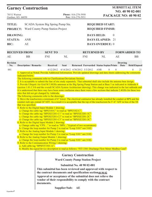
<strong>Garney</strong> <strong>Construction</strong>785 E WarrenGardner, KS 66030Phone: 816-278-5950Fax: 816-278-5931SUBMITTAL ITEMO. <strong>40</strong> <strong>90</strong> <strong>02</strong>-<strong>001</strong>PACKAGE O: <strong>40</strong> <strong>90</strong> <strong>02</strong>TITLE:PROJECT:DRAWIG:STATUS:BIC:<strong>SCADA</strong> System Big Spring Pump Sta.Ward County Pump Station ProjectANRAEREQUIRED START:REQUIRED FIISH:DAYS HELD: 0DAYS ELAPSED: 21DAYS OVERDUE: 0RECEIVED FROMAEBBSET TOFNINLRETURED BYFNI NLFORWARDED TOAEBBRevisiono.Description / RemarksReceivedSentDrawing<strong>Returned</strong> Forwarded Status Sepias Prints Date HeldElapsed<strong>001</strong> 4/12/2012 4/14/2012 4/30/2012 5/3/2012 ANR 0 0 0 211. Approved as Noted. Provide Additional Information. Provide updated drawings and data sheets addressing the commentsindicated below.The following comments refer to Clarifications/Deviations Section:2. It is acceptable to submit the line of site study separately. That submittal shall also include the antenna base design.3. Provide Ubiquiti Air Grid M 5.8GHz antennas at the Big Spring Pump Station and at Base 5 as indicated in Addenda 4(section 1.01.C.9.b and the overall <strong>SCADA</strong> System Architecture drawing). This change was indicated in the last addenda andit is understood that there may have been some confusion since there were a few sections that indicate 2.4GHz for these twosites that did not get changed by Addenda.The following comments refer to the drawings:4. Move the touchscreen a minimum of 6” lower. The electrical contractor has already installed the conduit at BPS and theconduit stub-ups extend 24”AFF. As a result it is acceptable that the top of the touchscreen be 5’-6” AFF in lieu of the 5ftthat was specified.5. Refer to the Digital Input Module 1 drawing:a. Change the cable tag “BPS3101C” to read as “BPS31<strong>02</strong>-C”.b. Change the cable tag “BPSXE3201-C1” to read as “BPSXE3201-1C”c. Change the cable tag “BPSXE3201-C2” to read as “BPSXE3201-2C”d. Change the cable tag “BPSXE3201-C3” to read as “BPSXE3201-3C”6. Refer to the Digital Input Module 2 drawing:a. Change cable tag “CPS…” to read as “BPS…”(typical of two occurrences)b. Change the loop number for Pump 2 to read as “Loop 3101” not 31<strong>02</strong>.7. Refer to the Analog Input Module 1 drawing:a. Change the loop number for Pump 2 to read as “Loop 3101” not 31<strong>02</strong>.8. Refer to the Analog Output Module 1 drawing:a. Change the loop number for Pump 2 to read as “Loop 3101” not 31<strong>02</strong>.9. Refer to the Communication Wiring 1 drawing:a. Add cable tag “BPSFIT3301-A”.b. Modify the signal/device description to read as follows: “FIT-3301 Discharge Flow Meter Modbus Card”Expedition ®<strong>Garney</strong> <strong>Construction</strong>Ward County Pump Station Project<strong>Submittal</strong> o. <strong>40</strong> <strong>90</strong> <strong>02</strong>-<strong>001</strong>This submittal has been reviewed and approved with respect tothe contract documents and specification section<strong>40</strong> <strong>90</strong> <strong>02</strong>Approval or acceptance of the submittal does not relieve thevendor of their responsibility to comply with the contractdocuments.Supplier/Sub: AE
SUBMITTALShttps://projectdox.freese.com/imarkupwg/form.asp?formid=6465&wfdirect=&debug=&con...Page 1 of 25/3/2012Project No:Project:Client:Contractor:CMD11269FCMAR Ward County Transmission System - Above SlabColorado River Municipal Water District<strong>Garney</strong>Shop Drawing #011<strong>SCADA</strong> for Big Spring Pump StationWORKFLOW COMPLETED 4/30/2012 1:27 PMSUBMITTAL INFORMATIONSUBMITTALTYPE:SUBMITTAL #: CONTRACTOR REF #: SPEC SECTION: PLAN SHEET: SUBMITTAL STATUS:ShopDrawing011<strong>40</strong> <strong>90</strong> <strong>02</strong>-<strong>001</strong><strong>40</strong> <strong>90</strong> <strong>02</strong>Approved As Noted,Additional InformationRequiredSUBMITTALDESCRIPTION:<strong>SCADA</strong> for Big Spring Pump StationUPLOAD SUPPORTING DOCUMENTS<strong>40</strong> <strong>90</strong> <strong>02</strong>-<strong>001</strong> <strong>SCADA</strong> <strong>BSPS</strong> <strong>Submittal</strong>.pdf 4/14/2012 2:39 PM Marcus GraceCONTRACTOR CERTIFICATIONCONTRACTOR COMMENTS:Big Spring Pump Station <strong>SCADA</strong> <strong>Submittal</strong> for review and approvalHOW WILL THE COPIES BE SUBMITTED:ElectronicNUMBER OF COPIES SUBMITTED: 1This shop drawing has been reviewed by the Contractor and certified to be in strict conformance with the Contract Documents as modified by addenda, field orders, andchange orders. Deviations can only be approved by field order or change order. Approval is only for conformance with the design concept of the project and compliancewith the intent of the information given in the Contract Documents. Contractor is responsible for dimensions to be confirmed and correlated at the job site; for informationthat pertains solely to the fabrication processes or to techniques of construction; and for the work of all trades.SUBMITTED BY: Marcus GraceDATE: 4/14/2012 2:39 PMREVIEWER COMMENTSREVIEWER NAME: REVIEWER EMAIL: COMPANY / ORGANIZATION DATE SENT: DATECOMPLETED:Jeff Hensleyjnh@freese.com<strong>40</strong>55 International Plaza4/16/20124/27/2012REVIEWERCOMMENTS:No Comments - See Rebecca Sandoval's comments.REVIEWER NAME: REVIEWER EMAIL: COMPANY / ORGANIZATION DATE SENT: DATECOMPLETED:RebeccaSandovalrs@freese.comFreese and Nichols, Inc4/16/20124/26/2012REVIEWERCOMMENTS:4/26/12Approved as Noted - Additional Information Required - See attached for comments.UPLOAD SUPPORTING REVIEW DOCUMENTSCMD11269_BPS_<strong>SCADA</strong>_Review_Comments_RS_04.26.12.pdfRemove 4/26/2012 8:04 PM Rebecca SandovalDISPLAY ROUTING SLIP
SUBMITTALShttps://projectdox.freese.com/imarkupwg/form.asp?formid=6465&wfdirect=&debug=&con...Page 2 of 25/3/2012Current Workflow Step: DCS Admin: Debby Greer Workflow Initiator: Marcus Grace(Click on the Names above to Email User)FNI Forms v1.04
Rebecca SandovalFreese and Nichols, Inc.CMD11269 - CRMWD Above Slab ProjectBPS <strong>SCADA</strong> Shop Drawing <strong>Submittal</strong>4/26/2012Refer to Jeff Hensley for additional comments.1. Approved as Noted. Provide Additional Information. Provide updated drawings and data sheetsaddressing the comments indicated below.The following comments refer to Clarifications/Deviations Section:2. It is acceptable to submit the line of site study separately. That submittal shall also include theantenna base design.3. Provide Ubiquiti Air Grid M 5.8GHz antennas at the Big Spring Pump Station and at Base 5 as indicatedin Addenda 4 (section 1.01.C.9.b and the overall <strong>SCADA</strong> System Architecture drawing). This change wasindicated in the last addenda and it is understood that there may have been some confusion since therewere a few sections that indicate 2.4GHz for these two sites that did not get changed by Addenda.The following comments refer to the drawings:4. Move the touchscreen a minimum of 6” lower. The electrical contractor has already installed theconduit at BPS and the conduit stub-ups extend 24”AFF. As a result it is acceptable that the top of thetouchscreen be 5’-6” AFF in lieu of the 5ft that was specified.5. Refer to the Digital Input Module 1 drawing:a. Change the cable tag “BPS3101C” to read as “BPS31<strong>02</strong>-C”.b. Change the cable tag “BPSXE3201-C1” to read as “BPSXE3201-1C”c. Change the cable tag “BPSXE3201-C2” to read as “BPSXE3201-2C”d. Change the cable tag “BPSXE3201-C3” to read as “BPSXE3201-3C”6. Refer to the Digital Input Module 2 drawing:a. Change cable tag “CPS…” to read as “BPS…”(typical of two occurrences)b. Change the loop number for Pump 2 to read as “Loop 3101” not 31<strong>02</strong>.7. Refer to the Analog Input Module 1 drawing:a. Change the loop number for Pump 2 to read as “Loop 3101” not 31<strong>02</strong>.8. Refer to the Analog Output Module 1 drawing:a. Change the loop number for Pump 2 to read as “Loop 3101” not 31<strong>02</strong>.9. Refer to the Communication Wiring 1 drawing:a. Add cable tag “BPSFIT3301-A”.b. Modify the signal/device description to read as follows: “FIT-3301 Discharge Flow MeterModbus Card”<strong>Submittal</strong> Review Comments Page 1 of 1
<strong>Garney</strong> <strong>Construction</strong>785 E WarrenGardner, KS 66030Phone: 816-278-5950Fax: 816-278-5931SUBMITTAL ITEMO. <strong>40</strong> <strong>90</strong> <strong>02</strong>-<strong>001</strong>PACKAGE O: <strong>40</strong> <strong>90</strong> <strong>02</strong>TITLE:PROJECT:DRAWIG:STATUS:BIC:<strong>SCADA</strong> System Big Spring Pump Sta.Ward County Pump Station ProjectOPNFNIREQUIRED START:REQUIRED FIISH:DAYS HELD: 0DAYS ELAPSED: 2DAYS OVERDUE: 0RECEIVED FROMAEBBSET TOFNINLRETURED BYFNI NLFORWARDED TOAEBBRevisiono.Description / RemarksReceivedSentDrawing<strong>Returned</strong> Forwarded Status Sepias Prints Date HeldElapsed<strong>001</strong> 4/12/2012 4/14/2012 OPN 0 0 0 2<strong>SCADA</strong> System for Big Spring Pump Station<strong>Garney</strong> <strong>Construction</strong>Ward County Pump Station Project<strong>Submittal</strong> o. <strong>40</strong> <strong>90</strong> <strong>02</strong>-<strong>001</strong>This submittal has been reviewed and approved with respect tothe contract documents and specification section<strong>40</strong> <strong>90</strong> <strong>02</strong>Approval or acceptance of the submittal does not relieve thevendor of their responsibility to comply with the contractdocuments.Supplier/Sub: AEDate: ______________ 4-14-12 Reviewed by: _________________M. GraceExpedition ®
815 OFFICE PARK CIRCLE LEWISVILLE, TX 75057PHONE 972- 221- 4849 FAX 972- 420- 4842COLORADO RIVER MUNICPAL WATER DISTRICTWARD COUNTY WATER SUPPLY PROJECTCONTRACT CProject No. CMD-11269PROJECT DESIGN SUBMITTALFOR BIG SPRING PUMP STATIONSpecification Section<strong>40</strong> <strong>90</strong> <strong>02</strong>PRIME CONTROLSPROJECT NO. 1201030APRIL 9, 2012
815 OFFICE PARK CIRCLE LEWISVILLE, TX 75057PHONE 972- 221- 4849 FAX 972- 420- 4842Table of ContentsSection Description Specification1 Deviations & Clarifications N/A2 Input / Output List <strong>40</strong> <strong>90</strong> <strong>02</strong>.143 Modicon Quantum PLC Equipment <strong>40</strong><strong>90</strong><strong>02</strong>.2014 Hirschmann Ethernet Equipment <strong>40</strong><strong>90</strong><strong>02</strong>.2155 Uninterruptible Power Supply (UPS) <strong>40</strong><strong>90</strong><strong>02</strong>.2106 Control Panel & Auxiliaries <strong>40</strong><strong>90</strong><strong>02</strong>.2087 RF Equipment <strong>40</strong><strong>90</strong><strong>02</strong>.2118 Sample Display Screen N/A9 Control Panel Wiring Diagrams <strong>40</strong><strong>90</strong><strong>02</strong>.208
815 OFFICE PARK CIRCLE LEWISVILLE, TX 75057PHONE 972- 221- 4849 FAX 972- 420- 4842SECTION 1Deviations & Clarifications
815 OFFICE PARK CIRCLE LEWISVILLE, TX 75057PHONE 972- 221- 4849 FAX 972- 420- 4842Deviations and ClarificationsClarifications:Section <strong>40</strong> <strong>90</strong> <strong>02</strong> Supervisory Control and Data Acquisition (<strong>SCADA</strong>) SystemSub-section 1.01 H2 a, b, c: Path Study for Radio Communications -Big SpringPump Station (BPS)Clarification: Path studies (physical and computer generated) will be submittedunder separate cover for all locations.Deviations:Section <strong>40</strong> <strong>90</strong> <strong>02</strong> Supervisory Control and Data Acquisition (<strong>SCADA</strong>) SystemSub-section 1.01 B5: Big Spring Pump Station (BPS)Specification: The PLC shall be connected to a ProSoft 2.4GHz radio viaRS232 cable.Submitted: PLC to radio connection via Ethernet.Justification: To enable power monitoring of electrical equipment ifdesired.Sub-section 1.01 C9b: Big Spring Pump Station (BPS)Specification: The antennas at Base 5 and Big Spring Pump Station shallbe Ubiquiti Air Grid M 5.8GHz 17”x24” antenna, noapproved equal.Submitted: ProSoft model number RadioLinx A2410NJ-DY.Justification: Per spec sub-sections 1.01 C5, 2.12 A, and to match radioand antenna wavelengths.Sub-section 2.08 D:Specification: Interposing relays contained in this cabinet shall be3PDT…Relays shall be Square D KU13M1P14 or approvedequal.Submitted: Phoenix Contact PLC relays.
815 OFFICE PARK CIRCLE LEWISVILLE, TX 75057PHONE 972- 221- 4849 FAX 972- 420- 4842Justification: To be able to fit equipment into a wall mount enclosure asspecified is sub-section 2.08B and to meet sub-section 2.01L6 “Spare I/O shall be wired to spare terminal blocks, thisstyle and type of relay was required.Sub-section 2.16 A: Graphic user interface (GUI) Touch Screens (TPS, OPS,WPS, BPS)Specification: Touch screens shall be 14-inch LCD terminals with full touchscreen capabilities as manufactured by Allen BradleyPanelView Plus or approved equal..Submitted: Magelis 15" Touch Screen Color GUIJustification: Submitted as an equal and to maintain manufacturerconsistency.
815 OFFICE PARK CIRCLE LEWISVILLE, TX 75057PHONE 972- 221- 4849 FAX 972- 420- 4842SECTION 2Input / Output List
PRIME CONTROLS, LPCOLORADO RIVER MUNICIPAL WATER DISTRICTWARD COUNTY WATER SUPPLY PROJECTPROJECT No. 1201030I/O POINT INFORMATION PLC INFORMATION HMI INFORMATIONENG. ENG.POINTLOOPPLCEQUIPMENT TAG NUMBER I/O POINT TAG DESCRIPTION FUNCTIONP&IDPLC NAMETYPENUMBERADDRESS RACK SLOT CHANNEL ENG. LO LO LOW HI HI HIUNITS UNITSUNITS ALARM ALARM ALARM ALARMLOW HIGHPump P1 BPS-3101MI Pump P1 Run Status status DI 3101 BPS 10<strong>001</strong> 1 05 01 off runningPump P1 BPS-3101YI Pump P1 Auto Enabled status DI 3101 BPS 100<strong>02</strong> 1 05 <strong>02</strong> local autoPump P1 BPS-3101MAL Pump P1 VFD Fault alarm DI 3101 BPS 10003 1 05 03 normal faultPump P1 BPS-3101MHT Pump P1 High Motor Temp alarm DI 3101 BPS 10004 1 05 04 normal hi tempPump P1 BPS-3101HP Pump P1 High Pressure alarm DI 3101 BPS 10005 1 05 05 normal hi pressXE-3201-1/2 BPS-3201XA Pump Building Intrusion Alarm alarm DI 3201 BPS 10006 1 05 06 normal intrusionspare DI DI BPS 10007 1 05 07spare DI DI BPS 10008 1 05 08spare DI DI BPS 10009 1 05 09spare DI DI BPS 1<strong>001</strong>0 1 05 10spare DI DI BPS 1<strong>001</strong>1 1 05 11spare DI DI BPS 1<strong>001</strong>2 1 05 12spare DI DI BPS 1<strong>001</strong>3 1 05 13spare DI DI BPS 1<strong>001</strong>4 1 05 14spare DI DI BPS 1<strong>001</strong>5 1 05 15BPS-PLC Loss of AC Power alarm DI BPS 1<strong>001</strong>6 1 05 16 loss of power normalPump P2 BPS-31<strong>02</strong>MI Pump P2 Run Status status DI 31<strong>02</strong> BPS 1<strong>001</strong>7 1 06 01 off runningPump P2 BPS-31<strong>02</strong>YI Pump P2 Auto Enabled status DI 31<strong>02</strong> BPS 1<strong>001</strong>8 1 06 <strong>02</strong> local autoPump P2 BPS-31<strong>02</strong>MAL Pump P2 VFD Fault alarm DI 31<strong>02</strong> BPS 1<strong>001</strong>9 1 06 03 normal faultPump P2 BPS-31<strong>02</strong>MHT Pump P2 High Motor Temp alarm DI 31<strong>02</strong> BPS 10<strong>02</strong>0 1 06 04 normal hi tempPump P2 BPS-31<strong>02</strong>HP Pump P2 High Pressure alarm DI 31<strong>02</strong> BPS 10<strong>02</strong>1 1 06 05 normal hi pressLSH-3<strong>40</strong>1 BPS-3<strong>40</strong>1LAH Flow Meter Vault High Water Level alarm DI 3<strong>40</strong>1 BPS 10<strong>02</strong>2 1 06 06 normal floodedspare DI DI BPS 10<strong>02</strong>3 1 06 07spare DI DI BPS 10<strong>02</strong>4 1 06 08spare DI DI BPS 10<strong>02</strong>5 1 06 09spare DI DI BPS 10<strong>02</strong>6 1 06 10spare DI DI BPS 10<strong>02</strong>7 1 06 11spare DI DI BPS 10<strong>02</strong>8 1 06 12spare DI DI BPS 10<strong>02</strong>9 1 06 13spare DI DI BPS 10030 1 06 14spare DI DI BPS 10031 1 06 15spare DI DI BPS 10032 1 06 16Pump P1 BPS-3101HSH Pump P1 <strong>SCADA</strong> Stop / Start command DO 3101 BPS 00<strong>001</strong> 1 11 01 stop runPump P1 BPS-3101HS Pump P1 <strong>SCADA</strong> Remote E-Stop command DO 3101 BPS 000<strong>02</strong> 1 11 <strong>02</strong> stop e-stopspare DO DO BPS 00003 1 11 03spare DO DO BPS 00004 1 11 04spare DO DO BPS 00005 1 11 05spare DO DO BPS 00006 1 11 06spare DO DO BPS 00007 1 11 07Pump P2 BPS-31<strong>02</strong>HSH Pump P2 <strong>SCADA</strong> Stop / Start command DO 31<strong>02</strong> BPS 00008 1 11 08 stop runPump P2 BPS-31<strong>02</strong>HS Pump P2 <strong>SCADA</strong> Remote E-Stop command DO 31<strong>02</strong> BPS 00009 1 11 09 stop e-stopspare DO DO BPS 0<strong>001</strong>0 1 11 10spare DO DO BPS 0<strong>001</strong>1 1 11 11spare DO DO BPS 0<strong>001</strong>2 1 11 12spare DO DO BPS 0<strong>001</strong>3 1 11 13spare DO DO BPS 0<strong>001</strong>4 1 11 14spare DO DO BPS 0<strong>001</strong>5 1 11 15spare DO DO BPS 0<strong>001</strong>6 1 11 16Pump P1 BPS-3101SI Pump P1 Speed Feedback indication AI 3101 BPS 30<strong>001</strong> 1 13 01 0 100 % 5 10 <strong>90</strong> 95Spare AI AI BPS 300<strong>02</strong> 1 13 <strong>02</strong> 0 0 0 0 0Spare AI AI BPS 30003 1 13 03 0 0 0 0 0Spare AI AI BPS 30004 1 13 04 0 0 0 0 0Pump P2 BPS-31<strong>02</strong>SI Pump P2 Speed Feedback indication AI 31<strong>02</strong> BPS 30005 1 13 05 0 100 % 5 10 <strong>90</strong> 95Spare AI AI BPS 30006 1 13 06 0 0 0 0 0Spare AI AI BPS 30007 1 13 07 0 0 0 0 0Spare AI AI BPS 30008 1 13 08 0 0 0 0 0Pump P1 BPS-3101SC Pump P1 Speed Setpoint command AO 3101 BPS <strong>40</strong><strong>001</strong> 1 15 01 0 100 % 5 10 <strong>90</strong> 95Spare AO AO BPS <strong>40</strong>0<strong>02</strong> 1 15 <strong>02</strong> 0 0 0 0 0Spare AO AO BPS <strong>40</strong>003 1 15 03 0 0 0 0 0Spare AO AO BPS <strong>40</strong>004 1 15 04 0 0 0 0 0Pump P2 BPS-31<strong>02</strong>SC Pump P2 Speed Setpoint command AO 31<strong>02</strong> BPS <strong>40</strong>005 1 15 05 0 100 % 5 10 <strong>90</strong> 95Spare AO AO BPS <strong>40</strong>006 1 15 06 0 0 0 0 0Spare AO AO BPS <strong>40</strong>007 1 15 07 0 0 0 0 0Spare AO AO BPS <strong>40</strong>008 1 15 08 0 0 0 0 0FIT-3301 BPS-3301FI Discharge Flow Meter indication RS-485 3301 BPS 1 4 01 0 5 MGD 0.25 0.5 4.5 4.75NORMAL / OFFCONDITIONALARM / ONCONDITION4/4/2012 4:35 PMBIG SPRING PUMP STATIONI/O POINT TRACKING LIST 1 of 1
815 OFFICE PARK CIRCLE LEWISVILLE, TX 75057PHONE 972- 221- 4849 FAX 972- 420- 4842SECTION 3Modicon Quantum PLC Equipment
BPS PLC & AUXILIARIES DATA SHEETSection 3 – CPUManufacturer:Quantity / Description:Model / Part Number:Location:Modicon Quantum(1) Central Processing Unit1<strong>40</strong>CPU53414BBig Spring Pump Station RTUSection 3.1 – Power Supply 20 WattManufacturer:Modicon QuantumQuantity / Description:(1) Power Supply 20WModel / Part Number:1<strong>40</strong>CPS11420Location:Big Spring Pump Station RTUSection 3.2 – 16 Position BackplaneManufacturer:Modicon QuantumQuantity / Description:(1) 16 Position BackplaneModel / Part Number:1<strong>40</strong>XBP01600Location:Big Spring Pump Station RTUSection 3.3 – Discrete Input Module, 16 PointManufacturer:Modicon QuantumQuantity / Description:(2) Discrete Input Module 16 PointModel / Part Number:1<strong>40</strong>DDI84100Location:Big Spring Pump Station RTUSection 3.4 – Discreet Relay Output Module, 16 PointManufacturer:Modicon QuantumQuantity / Description:(1) Discreet Relay Ouput Module 16 PointModel / Part Number:1<strong>40</strong>DRA8<strong>40</strong>00Location:Big Spring Pump Station RTUSection 3.5 – Analog Input Module, 8 PointManufacturer:Modicon QuantumQuantity / Description:(1) Analog Input Module, 8 PointModel / Part Number:1<strong>40</strong>ACI03000Location:Big Spring Pump Station RTUSection 3.6 – Analog Output Module, 8 PointManufacturer:Modicon QuantumQuantity / Description:(1) Analog Output Module, 8 PointModel / Part Number:1<strong>40</strong>ACO13000Location:Big Spring Pump Station RTUSection 3.7 – I/O Card Edge ConnectorsManufacturer:Modicon QuantumQuantity / Description:(5) <strong>40</strong> Position Terminal StripModel / Part Number:1<strong>40</strong>XTS0<strong>02</strong>00Location:Big Spring Pump Station RTU
Section 3.8 – Ethernet ModuleManufacturer:Quantity / Description:Model / Part Number:Location:Square D / Quantum(1) Ethernet Module1<strong>40</strong>NOE77101Big Spring Pump Station RTUSection 3.9 – Graphic User Interface (GUI)Manufacturer:Square D /MagelisQuantity / Description:(1) 15" Touch Screen Color GUIModel / Part Number:XBTGT73<strong>40</strong>Location:Big Spring Pump Station RTU
0Simple and complex applicationsComplex applications1232 racks (1 main + 1 extension)31 drops x 2 racks (1 main + 1 extension)3 networks with 63 single-rack drops1<strong>02</strong>4 input channels and 1<strong>02</strong>4 output channels (max. 27 slots)31,744 input channels and 31,744 output channels8000 input channels and 8000 output channels per network64 input channels and 64 output channels (max. 27 slots)1984 input channels and 1984 output channels500 input channels and 500 output channels per networkIntrinsically safe I/O, high-speed counter, axis control, interrupt inputs, serial link, accurate time stamping62 integrated RS 232 Modbus master or ASCII ports on port no. 1 via EFB XXMIT on Concept or XMIT module on ProWORXNot limited on local rack (max. 27 slots), 4 on remote rack (RIO), 2 on distributed rack (DIO)366 “option” modules on local rack1 integrated port, 6 “option” modules on local rack6 “option” modules on local rack<strong>40</strong> to 80 programmable channels 60 to 100 programmable channelsPower supplies, remote I/O network, Modbus Plus modules, Ethernet TCP/IP modulesYesYes64 Kwords896 Kb 2.5 Mb64 Kbps I/O57 Kwords I/O–1<strong>40</strong>CPU43412A (3) 1<strong>40</strong>CPU53414B (4)2/19(3) CPU able to migrate from Concept to Unity Pro .(4) CPU able to migrate from Concept to Unity Pro with Unity Pro software version u 3.0.4567891<strong>02</strong>/15
PresentationModicon ® Quantum automation platformConcept /ProWORX standard CPUs12345678PresentationQuantum CPUs that are compatible with Concept or ProWORX software aresingle-slot PLCs with built-in executive memory, application memory andcommunication ports. With the memory components on-board, you do not needextra chips or cartridges for configuration.Flash-based executive memoryQuantum CPUs use flash memory technology to support the CPU's executivememory and instruction set. Flash is a state-of-the-art, non-volatile memorytechnology that enables field upgrades by downloading files over the Modbus ® orModbus Plus port as new features and maintenance updates become available.Memory backup and protectionThe CPUs store the application program in battery-backed RAM. This battery islocated on the front of the module and can be replaced while the CPU is running.To protect the application program from inadvertent changes during operation, theprocessors feature a memory-protect slide switch. An LED goes on when this switchis activated.Math coprocessorFor math-intensive applications, a math coprocessor is available on select CPUmodels. The coprocessor significantly improves execution times for the 984 ProcessControl Function Library (PCFL) and Equation Editor, as well as math operations inthe IEC languages. Improved floating point execution times mean more power forprocessing process algorithms and math calculations.Write protectionPLC write protection minimizes the possibility of a programmer inadvertently writingfrom a source PLC to a memory area in a destination PLC . Whatever data is notenabled is prevented from writing, both locally and over the network. This dataprotection option helps to ensure security against data transfer errors.Communication portsCPUs support Modbus ® or Modbus Plus networking strategies. Simple rotaryswitches on the back of the modules are used to define the network address of theModbus Plus port(s). Each device on a Modbus Plus network must have a uniqueaddress in the range 1...64. Modbus ® port settings include: baud rate, parity, numberof data bits, number of stop bits, protocol and Slave address. By default, thesesettings are 9600 bps, even parity, 8 data bits, 1 stop bit, RTU mode and address 1.A switch on the front of the CPUs can be used to configure the Modbus ® port as amodem communication interface (2<strong>40</strong>0 bps, even parity, 7 data bits, 1 stop bit,ASCII mode and address 1).The 1<strong>40</strong> CPU 434 12A and 1<strong>40</strong> CPU 534 14B processors have 2 serial Modbus ®ports:®b Modbus port 1, with full modem interfacing ability®b Modbus port 2, with RTS/CTS flow control (does not support modem connection)91<strong>02</strong>/16
DescriptionModicon ® Quantum automation platformConcept /ProWORX standard CPUs12345678DescriptionThe 1<strong>40</strong> CPU ppp processor front panel comprises:1 Model number and color code2 LED array3 Removable, hinged door and customizable identification label4 Battery slot5 Two slide switches6 One Modbus port A7 One Modbus port B8 One Modbus Plus portNote:The 1<strong>40</strong> CPU 113 0p processors have one Modbus and one Modbus Pluscommunication port.123Slide switchesEach of the two slide switches has three-position functionality:The left slide switch activates the memory write-protection. In the upper position,write protection is enabled; in the middle position, write protection is disabled.4mem prtoffnot usedASCIIRTUmemThe right slide switch determines the startup communication parameters for theModbus port. The middle position, RTU, is the factory-set default. The upperposition, ASCII, is for modem communications (1). If you need to set special startupparameters for the Modbus port – for example, if your Modbus address is not 1 – youcan set application-specific parameters in memory and set the slide switch in thebottom position.5Language choicesAdvanced IEC 61131-3 languagesQuantum's 5 IEC 61131-3 languages are:b Sequential Functional Chart: provides overall structure and coordination forprocess or machine control applications.b Function Block Diagram: particularly well suited to process control applications.b Ladder Language: excellent for combinational and interlocking logic.b Structured Text: higher level language that simplifies creating complex algorithmsand data manipulation.b Instruction List: low level language for optimizing the size of the program codegenerated.67984 Ladder LogicA high performance, low level language whose application source code resides inthe controller.A full set of over 80 instructions is included with every Quantum CPU. The 984instruction set helps ensure compatibility and easy integration paths for installedModicon applications, including:b Immediate I/O access and interrupt servicingb Equation editor89(1) 2<strong>40</strong>0 bps, even parity, 7 data bits, 1 stop bit, ASCII mode and address 1.1<strong>02</strong>/17
CharacteristicsModicon ® Quantum automation platformConcept /ProWORX standard CPUs1CharacteristicsModule type 1<strong>40</strong> CPU 113 <strong>02</strong> 1<strong>40</strong> CPU 113 03 1<strong>40</strong> CPU 434 12A 1<strong>40</strong> CPU 534 14BFunctional safety certification –ApprovalsUL 508, CSA 22,2-142, C UL, FM Class 1 Div. 2, eProcessors 80186 804862Math coprocessor No YesClock speed MHz 20 66 100User memory Max. IEC program 109 Kb 368 Kb 896 Kb 2.5 MbMax. LL 984 program 8 Kwords 16 Kwords 64 Kwords3Capacity Bits bps 8192 I/8192 Q 64 K combinedRegisters words 9999 max. 57 K max.Extended memory words – 96 KLogic solve time (984 LL instructions) ms/K 0.3…1.4 0.1…0.54Watchdog timer ms 250 (software-adjustable)Real-time clock accuracy s/day ± 8 at 0…60°CLocal I/O Maximum I/O words 64 I/64 QRemote I/O (RIO) I/O words/drop 64 I/64 Q5Number of drops 31Number of networks 2Distributed I/O (DIO) I/O words/drop 30 I/32 QI/O words/network500 I/500 QDrops/network 6367Number of networks 3Communication ports Modbus (RS 232) 1 2Modbus Plus 1Maximum number of NOM, NOE, CRP or MMSmodules2 6Key switch No YesMemory backup Product reference 9<strong>90</strong> XCP 980 00Battery typeLithiumVoltage V 3 c8Capacity mAh 1200Typical current μA 5 7 45 85Maximum current μA 110 210 70 135Storage life yr 109Bus current required mA 780 7<strong>90</strong> 12501<strong>02</strong>/18
ReferencesModicon ® Quantum automation platformConcept /ProWORX standard CPUsMigration of Quantum CPUsAs both the 1<strong>40</strong> CPU 434 12A and 1<strong>40</strong> CPU 534 14B Quantum CPUs are compatiblewith Concept or ProWORX software, they can be upgraded to be compatible with theUnity Pro software without any hardware modification.. This process of migratingfrom Concept to Unity Pro is achieved by updating the CPU operating system.This update is performed with the aid of the OS-Loader tool included with Unity Pro(see page 7/29).The upgraded processor 1<strong>40</strong> CPU 434 12A is then equivalent to the correspondingUnity processor 1<strong>40</strong> CPU 434 12U.Note: Migration of the 1<strong>40</strong> CPU 534 14B processor requires the version of Unity Pro u 3.0.CPUsMemory (total) Coprocessors Safety Reference Weightkg256 Kbytes No – 1<strong>40</strong>CPU113<strong>02</strong> 0.300512 Kbytes No – 1<strong>40</strong>CPU11303 0.3<strong>001</strong>232 Mbytes Integrated – 1<strong>40</strong>CPU43412A 0.8504 Mbytes Integrated – 1<strong>40</strong>CPU53414B 0.850AccessoriesDescription Length Safety Reference(1)Programming cable forModbus interfaceWeightkg3.7 m – 9<strong>90</strong>NAA26320 0.3<strong>001</strong>5 m – 9<strong>90</strong>NAA26350 1.820Backup battery – – 9<strong>90</strong>XCP98000 –45Quantum automation serieshardware reference guide– – 8<strong>40</strong>USE1000p –(1) Add one of the following digits at the end of the reference: 0: English, 1: French, 2: German,3: Spanish.67891<strong>02</strong>/19
1ata Bulletin8000HO046410/2004North Andover, MA USAMODICON® QUANTUM 1<strong>40</strong>CPS11420 SUMMABLE ACPOWER SUPPLYGeneral DescriptionThe Quantum 1<strong>40</strong>CPS11420 Summable AC Power Supply providespower to the system backplane while protecting the system from noiseand nominal voltage swings. All Quantum power supplies feature overcurrent and under voltage protection. In the event of an unforeseenloss of power, the Quantum power supplies ensure that the system hasadequate time for a safe and orderly shutdown.Wiring examples(refer to user guide for important safety information):This diagram is valid for both 115VAC and 230 VAC source voltages.1234567Power loss alarmInstall jumper for115 VAC operation.AC LineAC NeutralThe 1<strong>40</strong>CPS11420 power supply converts the incoming power sourceto a regulated +5VDC to support the CPU, the local I/O andcommunication option modules mounted in the backplane. Powerbetween the field sensors and the Quantum I/O points is not providedby these power supply modules.A summable power supply such as the 1<strong>40</strong>CPS11420 can operate ineither Standalone mode or Summable mode. Whenever two summablepower supplies (must be the same model) are combined in the samebackplane, they automatically operate in summable mode delivering20A of power to the back plane.The Quantum power supply can be inserted into any backplane slot.However, for best heat dissipation and maximum life it is recommendedthat the power supply/s be inserted in the outside slot/s.As an option, modules can be ordered with a conformal coating appliedto protect the internal circuitry from corrosive gases such as Chlorine,Nitric Oxide, Hydrogen Sulfide and Sulfur Dioxide.1<strong>40</strong>CPS 114 20AC Power SupplyPwr ok*A removable terminal strip allows for easy maintenance.Removable terminal strip is included.Visual status and diagnostic information isavailable on the face of the module as LED’s.Pwr ok Green Power is supplied to the bus1<strong>40</strong>XTSStandard, Screw Type, <strong>40</strong> pointsOptional rack accessories are ordered separately.1<strong>40</strong>XCP500<strong>001</strong><strong>40</strong>XCP51000Dummy module without terminal blockDummy module with cover
Modicon Quantum 1<strong>40</strong>CPS11420 Summable AC Power Supply8000HO0464SpecificationsInput VoltageInput FrequencyInput Voltage TotalHarmonic DistortionInput CurrentInrush CurrentVA RatingInput Power InterruptionExternal FusesOutput Voltage to BusMaximum Current to BusMinimum Current to BusProtection93…132 VAC; 170…264VAC47 … 63 HzLess than 10% of the fundamental rms value1.3 A @ 115 VAC, 0.75 A @ 230 VAC38 A @ 115 VAC, 19 A @ 230 VAC130 VA1/2 cycle @ full load & minimum rated line voltage /frequency. No less than 1 second between interruptions.2.0 A slow blow recommended(part #0435<strong>02</strong>515 or equivalent)5.1 VDC11 A standalone, 20 A summable0.3 AOver Current, Over Voltagemin. 101.5 mm(4.0 in)Internal Power Dissipation 6.0 + 1.5 x I OUT in Watts (where I OUT is in Amperes)Operating ModeStandalone/SummableStorage Temperature -<strong>40</strong> ... +85 degrees C (-<strong>40</strong> … 185 degrees F)Operating TemperatureRelative HumidityWeight0 ... 60 degrees C (32 … 1<strong>40</strong> degrees F)0 … 95% Non-condensing @ 60 degrees C2.0 lb (1 kg) Maximummin. 25.4 mm(1.0 in)min. 101.5 mm(4.0 in)min. 25.4 mm(1.0 in)RFI Immunity80 … 1000 MHz, 10 V/m (meets IEC 1000-4-3)Ground Continuity2 kV shield to groundElectrostatic Discharge 8 kV air/4kV contact (meets IEC 1000-4-2)Agency ApprovalsUL 508, CSA 22.2-142, CE, FM Class 1 Div 2Software SupportConcept, ProWORX®, UnitySchneider Electric USAOne High StreetNorth Andover, MA 01845-26991-800-468-5342For detailed technical documentation visit:www.us.telemecanique.comThis document, and the information contained herein, is to be used exclusively by system integrators andconsulting engineers for the sole purpose of specifying Schneider Electric products or for submittingrelated documentation in support of engineering project proposals. This information is not intended for usein system design, implementation or installation. No responsibility is assumed by Schneider Electric for anyconsequences arising out of the use of this material.© 2004 Schneider Electric All Rights Reserved2
ata Bulletin8000HO041<strong>001</strong>0/2004North Andover, MA USAMODICON® QUANTUM 1<strong>40</strong>XBP01600 16-SLOTBACKPLANEGeneral DescriptionBackplanes are designed to mechanically secure and electricallyconnect all modules used in a Quantum system. The backplanecontains a passive circuit board which permits modules to communicatewith each other and to identify their slot numbers without further switchsettings.MOUNTING:1Six different backplane models are available with 2, 3, 4, 6, 10, or 16slots. Backplane slots are universal. In other words, any module mayfit into any slot. Almost all Quantum modules are designed to fit intosingle slots on a Quantum backplane; the only exception is the MMSSERCOS motion module and Unity processors, which require twocontiguous slots.There are no slot dependencies in a Quantum system, although powersupply modules should be mounted in the outermost slot positions foroptimum heat dissipation. Any backplane may be used in any of thethree system architectures supported by Quantum (standalone withlocal I/O, remote I/O or distributed I/O).21. Mount the module at an angle on to the two hookslocated near the top of the backplane.2. Swing the module down to make an electricalconnection with the backplane I/O bus connector.3. Tighten the screw at the bottom of the module tofasten it to the backplane.In a Quantum system, module addressing and configuration is handledby panel software. There are no DIP switches or other hardwaresettings.To meet vibration/shock specifications, the backplane must be mountedusing all specified mounting holes. The mounting surface should be flatto within +/- 1.0mm. The backplane is mounted using standardhardware (described below).The recommended length for the mounting screws should be within thefollowing range: 0.24 in (6 mm) - 0.52 in (13 mm).The head height of the screws should not exceed 0.14 in (3.5 mm).1/4” x 20 screws are recommended.670.74mm/26.41inPlease reference the Quantum AutomationHardware Reference Guide (8<strong>40</strong>USE10000) forimportant installation and grounding information.2<strong>90</strong>mm/11.42inOptional rack accessories are ordered separately.Ground Screws1<strong>40</strong>XCP500<strong>001</strong><strong>40</strong>XCP51000Blank module without terminal blockBlank module with cover
Modicon Quantum 1<strong>40</strong>XBP01600 16-SLOT BACKPLANE8000HO04100SpecificationsVibrationShock10 … 57 Hz at 0.075 mm d.a.; 57 … 150 Hz at 1g+/- 15g peak, 11 ms, half-sine waveStorage Temperature -<strong>40</strong> ... +85 degrees C (-<strong>40</strong> … 185 degrees F)Operating Temperature0 ... 60 degrees C (32 … 1<strong>40</strong> degrees F)min. 101.5 mm(4.0 in)Top of CabinetAltitudeRelative HumidityBackplane WeightRFI ImmunityGround ContinuityAgency Approvals0 … 95% Non-condensing @ 60 degrees C3.5 lbs (7.2 lb (3.27 kg) Maximum)80 … 1000 MHz, 10 V/m (meets IEC 1000-4-3)2 kV shield to groundElectrostatic Discharge 8 kV air/4kV contact (meets IEC 1000-4-2)Software Support2000 m. When altitude exceeds 2000 m, reduce the 60degrees C maximum operating temperature by 6degrees C per 1000 m of additional elevation.UL 508, CSA 22.2-142, CE, FM Class 1 Div 2Concept, ProWORX®, Unity, ProWORX® 32min. 25.4 mm(1.0 in)min. 101.5 mm(4.0 in)min. 25.4 mm(1.0 in)Schneider Electric USAOne High StreetNorth Andover, MA 01845-26991-800-468-5342For detailed technical documentation visit:www.us.telemecanique.comThis document, and the information contained herein, is to be used exclusively by system integrators andconsulting engineers for the sole purpose of specifying Schneider Electric products or for submittingrelated documentation in support of engineering project proposals. This information is not intended for usein system design, implementation or installation. No responsibility is assumed by Schneider Electric for anyconsequences arising out of the use of this material.© 2004 Schneider Electric All Rights Reserved2
ReferencesModicon ® Quantum automation platformDiscrete I/O modulesInput modules and output modules12ReferencesDiscrete input modulesVoltage Modularity Description Logic Safety Reference Weightkg5 V c TTL 32 inputs 4 groups of 8 inputs Negative – 1<strong>40</strong>DDI15310 0.45<strong>02</strong>4 V c 32 inputs 4 groups of 8 inputs Positive Non1<strong>40</strong>DDI35300 0.300interfering (1)Negative – 1<strong>40</strong>DDI35310 0.30096 inputs 6 groups of 16 inputs Positive – 1<strong>40</strong>DDI36<strong>40</strong>0 0.30032 inputs 4 groups of 8 inputs Positive – 1<strong>40</strong>DSI35300 0.3<strong>001</strong>0…60 V c 16 inputs 8 groups of 2 inputs Positive – 1<strong>40</strong>DDI84100 0.300332 inputs 4 groups of 8 inputs Positive – 1<strong>40</strong>DDI85300 0.295125 V c 24 inputs 3 groups of 8 inputs Positive – 1<strong>40</strong>DDI67300 0.30<strong>02</strong>4 V a 16 inputs No common point – – 1<strong>40</strong>DAI3<strong>40</strong>00 0.30032 inputs 4 groups of 8 inputs – – 1<strong>40</strong>DAI35300 0.3<strong>40</strong>448 V a 16 inputs No common point – – 1<strong>40</strong>DAI4<strong>40</strong>00 0.30032 inputs 4 groups of 8 inputs – – 1<strong>40</strong>DAI45300 0.3<strong>001</strong>15 V a 16 inputs No common point – – 1<strong>40</strong>DAI5<strong>40</strong>00 0.31016 inputs 2 groups of 8 inputs – – 1<strong>40</strong>DAI54300 0.300532 inputs 4 groups of 8 inputs – – 1<strong>40</strong>DAI55300 0.33<strong>02</strong>30 V a 16 inputs No common point – – 1<strong>40</strong>DAI7<strong>40</strong>00 0.35032 inputs 4 groups of 8 inputs – – 1<strong>40</strong>DAI75300 0.30067Discrete output modulesVoltage Description Logic Safety Reference Weightkg5 V c TTL 32 outputs 4 groups of 8 outputs Negative – 1<strong>40</strong>DDO15310 0.45<strong>02</strong>4 V c 32 outputs 4 groups of 8 outputs Positive Non1<strong>40</strong>DDO35300 0.450interfering (1)Positive– 1<strong>40</strong>DDO35301 0.450(2)Negative – 1<strong>40</strong>DDO35310 0.45096 outputs 6 groups of 16 outputs Positive – 1<strong>40</strong>DDO36<strong>40</strong>0 0.45010…30 V c 32 outputs 4 groups of 8 outputs Positive – 1<strong>40</strong>DVO85300 0.3008910…60 V c 16 outputs 2 groups of 8 outputs Positive – 1<strong>40</strong>DDO84300 0.45<strong>02</strong>4…125 V c 12 outputs 2 groups of 6 outputs Positive – 1<strong>40</strong>DDO88500 0.450Relay20…250 V a5…150 V c16 outputs No common point 1 “NO” contact – 1<strong>40</strong>DRA8<strong>40</strong>00 0.4108 outputs No common point 2 “NC” and “NO”contacts– 1<strong>40</strong>DRC83000 0.30<strong>02</strong>4…48 V a 16 outputs 4 groups of 4 outputs – – 1<strong>40</strong>DAO84220 0.45<strong>02</strong>4…115 V a 16 outputs No common point – – 1<strong>40</strong>DAO8<strong>40</strong>10 0.48524…230 V a 16 outputs No common point – – 1<strong>40</strong>DAO8<strong>40</strong>00 0.4851032 outputs 4 groups of 8 outputs – – 1<strong>40</strong>DAO85300 0.450100…230 V a 16 outputs 4 groups of 4 outputs – – 1<strong>40</strong>DAO84210 0.450(1) Version u 1.(2) Outputs protected against short-circuits and overloads by thermal monitoring.4/26
c24 V 10…60 V 125 V123496 32 16 32 246 4 8 4 316 8 2 8 8By group6 input words 4 input words 1 input word 2 input words56270 mA 250 mA 200 mA 300 mA 200 mAPositive7–1<strong>40</strong>DDI36<strong>40</strong>0 (1) 1<strong>40</strong>DSI35300 1<strong>40</strong>DDI84100 1<strong>40</strong>DDI85300 1<strong>40</strong>DDI673004/268(1) For connection, requires the Advantys Telefast ® ABE 7 pre-wired system with TSX CDP pp3 connection cables (with one HE10 connector at each end for 1group of 16 channels), see pages 4/32 and 9/9.9104/3
ReferencesModicon ® Quantum automation platformDiscrete I/O modulesInput modules and output modules12ReferencesDiscrete input modulesVoltage Modularity Description Logic Safety Reference Weightkg5 V c TTL 32 inputs 4 groups of 8 inputs Negative – 1<strong>40</strong>DDI15310 0.45<strong>02</strong>4 V c 32 inputs 4 groups of 8 inputs Positive Non1<strong>40</strong>DDI35300 0.300interfering (1)Negative – 1<strong>40</strong>DDI35310 0.30096 inputs 6 groups of 16 inputs Positive – 1<strong>40</strong>DDI36<strong>40</strong>0 0.30032 inputs 4 groups of 8 inputs Positive – 1<strong>40</strong>DSI35300 0.3<strong>001</strong>0…60 V c 16 inputs 8 groups of 2 inputs Positive – 1<strong>40</strong>DDI84100 0.300332 inputs 4 groups of 8 inputs Positive – 1<strong>40</strong>DDI85300 0.295125 V c 24 inputs 3 groups of 8 inputs Positive – 1<strong>40</strong>DDI67300 0.30<strong>02</strong>4 V a 16 inputs No common point – – 1<strong>40</strong>DAI3<strong>40</strong>00 0.30032 inputs 4 groups of 8 inputs – – 1<strong>40</strong>DAI35300 0.3<strong>40</strong>448 V a 16 inputs No common point – – 1<strong>40</strong>DAI4<strong>40</strong>00 0.30032 inputs 4 groups of 8 inputs – – 1<strong>40</strong>DAI45300 0.3<strong>001</strong>15 V a 16 inputs No common point – – 1<strong>40</strong>DAI5<strong>40</strong>00 0.31016 inputs 2 groups of 8 inputs – – 1<strong>40</strong>DAI54300 0.300532 inputs 4 groups of 8 inputs – – 1<strong>40</strong>DAI55300 0.33<strong>02</strong>30 V a 16 inputs No common point – – 1<strong>40</strong>DAI7<strong>40</strong>00 0.35032 inputs 4 groups of 8 inputs – – 1<strong>40</strong>DAI75300 0.30067Discrete output modulesVoltage Description Logic Safety Reference Weightkg5 V c TTL 32 outputs 4 groups of 8 outputs Negative – 1<strong>40</strong>DDO15310 0.45<strong>02</strong>4 V c 32 outputs 4 groups of 8 outputs Positive Non1<strong>40</strong>DDO35300 0.450interfering (1)Positive– 1<strong>40</strong>DDO35301 0.450(2)Negative – 1<strong>40</strong>DDO35310 0.45096 outputs 6 groups of 16 outputs Positive – 1<strong>40</strong>DDO36<strong>40</strong>0 0.45010…30 V c 32 outputs 4 groups of 8 outputs Positive – 1<strong>40</strong>DVO85300 0.3008910…60 V c 16 outputs 2 groups of 8 outputs Positive – 1<strong>40</strong>DDO84300 0.45<strong>02</strong>4…125 V c 12 outputs 2 groups of 6 outputs Positive – 1<strong>40</strong>DDO88500 0.450Relay20…250 V a5…150 V c16 outputs No common point 1 “NO” contact – 1<strong>40</strong>DRA8<strong>40</strong>00 0.4108 outputs No common point 2 “NC” and “NO”contacts– 1<strong>40</strong>DRC83000 0.30<strong>02</strong>4…48 V a 16 outputs 4 groups of 4 outputs – – 1<strong>40</strong>DAO84220 0.45<strong>02</strong>4…115 V a 16 outputs No common point – – 1<strong>40</strong>DAO8<strong>40</strong>10 0.48524…230 V a 16 outputs No common point – – 1<strong>40</strong>DAO8<strong>40</strong>00 0.4851032 outputs 4 groups of 8 outputs – – 1<strong>40</strong>DAO85300 0.450100…230 V a 16 outputs 4 groups of 4 outputs – – 1<strong>40</strong>DAO84210 0.450(1) Version u 1.(2) Outputs protected against short-circuits and overloads by thermal monitoring.4/26
1ata Bulletin8000HO049110/2004North Andover, MA USAMODICON® QUANTUM 1<strong>40</strong>DRA8<strong>40</strong>00 RELAY OUTPUTMODULEGeneral DescriptionThe Quantum 1<strong>40</strong>DRA8<strong>40</strong>00 RELAY Output Module provides (16x1)Normally Open Relay outputs.A Quantum removable terminal strip allows for easy maintenance.Wiring examples(refer to user guide for important safety information):Quantum backplanes (ordered separately) come in 2,3,4,6,10, and 16slot versions. Any Quantum module can be used in any slot. AQuantum power supply is required in each rack. The power supplyprovides logic power to all modules on the bus.RELAY 1 COMMONRELAY 2 COMMONRELAY 3 COMMONRELAY 4 COMMON24681357OUTPUT 1 N.O.OUTPUT 2 N.O.OUTPUT 3 N.O.OUTPUT 4 N.O.+VOLTAGESOURCE-See Note 1All Quantum I/O modules are optically isolated from the bus, ensuringsafe and trouble-free operation.Optionally, you can insert mechanical keys between the I/O module andthe terminal strip to ensure that the field wiring and the module type areproperly matched. Key codes are unique for each module type. Keykits are shipped with each I/O module.N/CRELAY 5 COMMONRELAY 6 COMMONRELAY 7 COMMONRELAY 8 COMMONN/CRELAY 9 COMMONRELAY 10 COMMONRELAY 11 COMMONRELAY 12 COMMON10121416182<strong>02</strong>22426289111315171921232527N/COUTPUT 5 N.O.OUTPUT 6 N.O.OUTPUT 7 N.O.OUTPUT 8 N.O.N/COUTPUT 9 N.O.OUTPUT 10 N.O.OUTPUT 11 N.O.OUTPUT 12 N.O.NOTE 1: For 125 VDC inductiveloads, external clamping isrecommended to extend relaycontact life (1N <strong>40</strong>04 or equivalent).NOTE 2: N/C=Not Connected.N.O.N.C.One of sixteen TypicalOutput XN.O.Relay XCommonAs an option, modules can be ordered with a conformal coating appliedto protect the internal circuitry from corrosive gases such as Chlorine,Nitric Oxide, Hydrogen Sulfide and Sulfur Dioxide.1<strong>40</strong>DRA 8<strong>40</strong> 00RELAY OutputActive1 92 103 114 125 136 147 158 16N/CRELAY 13 COMMONRELAY 14 COMMONRELAY 15 COMMONRELAY 16 COMMON30323436382931333537N/COUTPUT 13 N.O.OUTPUT 14 N.O.OUTPUT 15 N.O.OUTPUT 16 N.O.Visual status and diagnostic information isavailable on the face of the module as LED’s.Active Green Bus communication is active1…16 Green The output is ONN/C<strong>40</strong>39N/CRemovable terminal strip is ordered separately.1<strong>40</strong>XTS0<strong>02</strong>00Standard, Screw Type, <strong>40</strong> pointsOptional rack accessories are ordered separately.1<strong>40</strong>XCP500<strong>001</strong><strong>40</strong>XCP51000Dummy module without terminal blockDummy module with cover
Modicon Quantum 1<strong>40</strong>DRA8<strong>40</strong>00 Relay Output Module8000HO0491SpecificationsModule Type16 Normally Open RELAY pairsWorking VoltageMaximum Load CurrentEach pointEach point (30 … 150 VDC)Minimum Load CurrentEach point (30 …150 VDC)Mechanical Operations 10,000,00<strong>02</strong>0…250VAC; 5…30VDC; 30….150VDC (reduced load)25 A max at 250VAC VAC/30 or 30VDC @ 60 60 C C ambient, ambient, resist resist load load12 A Tungsten lamp load13 A @ a power factor of 0.41/8 1/4 hp @ 125/250 VAC300 mA (resistive load)100 mA (L/R = 10 msec)50mA (Minimum load current if contact is used at ratedloads of 5 … 150 VDC or 20 … 250 VAC)Derated to 0.5 A per pointElectrical Operations200,000 (resistive load @ max voltage and current)min. 101.5 mm(4.0 in)Top of CabinetElectrical Operations(30 to 150 VDC)Relay TypeMaximum surge current (per point)100,000 (300 mA resistive load)50,000 (500 mA resistive load)100,000 (100 mA L/R = 10 ms)Form A10 A capacitive load @ τ = 10 msSwitching Capability500 VA resistive loadResponse Time (resistive loads)10 ms (max) OFF to ON, 20 ms (max) ON to OFFOff State Leakage < 100 µABus current requiredChannel to Channel IsolationChannel to Bus Isolation1100 mA (max)1780 VAC rms for 1 minute1780 VAC rms for 1 minute; 2500 VDC for 1 minutemin. 25.4 mm(1.0 in)Storage Temperature -<strong>40</strong> ... +85 degrees C (-<strong>40</strong> … 185 degrees F)Power Dissipation5.5 W + (# of inputs ON X 0.5 W)min. 101.5 mm(4.0 in)min. 25.4 mm(1.0 in)Operating TemperatureRelative HumidityWeight0 ... 60 degrees C (32 … 1<strong>40</strong> degrees F)0 … 95% Non-condensing @ 60 degrees C2.0 lb (1 kg) MaximumRFI Immunity80 … 1000 MHz, 10 V/m (meets IEC 1000-4-3)Ground Continuity2 kV shield to groundElectrostatic Discharge 8 kV air/4kV contact (meets IEC 1000-4-2)Agency ApprovalsSoftware SupportUL 508, CSA 22.2-142, CE, FM Class 1 Div 2Concept, ProWORX®, Unity, ProWORX® 32Schneider Electric USAOne High StreetNorth Andover, MA 01845-26991-800-468-5342For detailed technical documentation visit:www.us.telemecanique.comIO Map1 Output wordThis document, and the information contained herein, is to be used exclusively by system integrators andconsulting engineers for the sole purpose of specifying Schneider Electric products or for submittingrelated documentation in support of engineering project proposals. This information is not intended for usein system design, implementation or installation. No responsibility is assumed by Schneider Electric for anyconsequences arising out of the use of this material.© 2004 Schneider Electric All Rights Reserved2
1ata Bulletin8000HO045310/2004North Andover, MA USAMODICON® QUANTUM 1<strong>40</strong>ACI03000 ANALOG INPUTMODULEGeneral DescriptionThe Quantum 1<strong>40</strong>ACI03000 Analog Input Module provides (8)differential analog input channels. Each channel is individuallyconfigurable for a 1 ... 5 VDC or 4 … 20 mA signal.This module has broken wire detection in current mode and undervoltage in voltage mode.Wiring examples(refer to user guide for important safety information):INPUT 1(-)N/CINPUT 2 (-)N/CN/CINPUT 3 (-)N/CINPUT 4 (-)N/CN/CINPUT 5 (-)N/CINPUT 6 (-)N/CN/CINPUT 7 (-)N/CINPUT 8 (-)N/CN/C246810121416182<strong>02</strong>22426283032343638<strong>40</strong>13579111315171921232527293133353739INPUT 1(+)I SENSE 1INPUT 2 (+)I SENSE 2N/CINPUT 3 (+)I SENSE 3INPUT 4 (+)I SENSE 4N/CINPUT 5 (+)I SENSEINPUT 6 (+)I SENSE 6N/CINPUT 7 (+)I SENSE 7INPUT 8 (+)I SENSE 8N/CRemovable terminal strip is ordered separately.CurrentSourceVoltageSourceA Quantum removable terminal strip allows for easy maintenance.Quantum backplanes (ordered separately) come in 2,3,4,6,10, and 16slot versions. Any Quantum module can be used in any slot. AQuantum power supply is required in each rack. The power supplyprovides logic power to all modules on the bus.All Quantum I/O modules are optically isolated from the bus, ensuringsafe and trouble-free operation. This isolation also allows modules tobe hot swapped.Optionally, you can insert mechanical keys between the I/O module andthe terminal strip to ensure that the field wiring and the module type areproperly matched. Key codes are unique for each module type. Keykits are shipped with each I/O module.As an option, modules can be ordered with a conformal coating appliedto protect the internal circuitry from corrosive gases such as Chlorine,Nitric Oxide, Hydrogen Sulfide and Sulfur Dioxide.1<strong>40</strong>1<strong>40</strong>ACI 030 00Analog Input12345678ActiveF12345678Visual status and diagnostic information isavailable on the face of the module as LED’s.Active Green Bus communication is activeF Red External fault detected1…8 Green The input is configured1…8 Red The Input is faulted1<strong>40</strong>XTS0<strong>02</strong><strong>001</strong><strong>40</strong>XTS<strong>001</strong>00Standard, Screw Type, <strong>40</strong> pointsIP 20 Finger Safe, <strong>40</strong> pointsOptional rack accessories are ordered separately.1<strong>40</strong>XCP500<strong>001</strong><strong>40</strong>XCP51000Dummy module without terminal blockDummy module with cover
Modicon Quantum 1<strong>40</strong>ACI03000 Analog Input Module8000HO0453SpecificationsModule TypeBus Current RequiredSignal TypeUpdate Time (in ms)Input Surge ToleranceInput to Input IsolationInput to Bus Isolation8 analog inputs, differential2<strong>40</strong> mA1…5VDC, 4…20mA5 ms for all channels+/-30VDC, +/-25mA30 VDC maximum1000 VDC, 3000 Vpp, for 1 minuteLinearity +/- 0.04%Internal FusesExternal Fuses - SupplyCommon Mode Rejection2A slow-blow (not user replaceable)500mA fast-blow recommended> -72 dB @ 60 HzFiltering Single pole low pass with -3 dB cutoff @ 15 Hz, +/- 20%Input TypeDifferentialSignal Type1 to 5 VDC4 to 20 mAmin. 101.5 mm(4.0 in)Input impedanceAbsolute Maximum InputError at 25 degrees C> 20 MΩ50 VDC0.05% typical, 0.1% max250 Ω +/− 0.03%25 mAResolution12 bitsAccuracy Drift with Temperature0.0<strong>02</strong>5% / degree C typical, 0.005% / degree C maxPower Dissipation2 WStorage Temperature-25 to +80 degrees COperating Temperature0 to 60 degrees CRelative Humidity5 … 95% Non-condensingmin. 25.4 mm(1.0 in)WeightEMC Immunity2.0 lb (1 kg) MaximumIEC1131 - Surge on aux power supply 500 Vmin. 101.5 mm(4.0 in)min. 25.4 mm(1.0 in)EMC EmissionsAgency ApprovalsEN50081-2 (limitation A)UL, CUL, CSA, CE, FM Class 1 Div 2Software SupportConcept, ProWORX®, UnityIO Map9 Input wordsSchneider Electric USAOne High StreetNorth Andover, MA 01845-26991-800-468-5342For detailed technical documentation visit:www.us.telemecanique.comThis document, and the information contained herein, is to be used exclusively by system integrators andconsulting engineers for the sole purpose of specifying Schneider Electric products or for submittingrelated documentation in support of engineering project proposals. This information is not intended for usein system design, implementation or installation. No responsibility is assumed by Schneider Electric for anyconsequences arising out of the use of this material.© 2004 Schneider Electric All Rights Reserved2
1ata Bulletin8000HO045610/2004North Andover, MA USAMODICON® QUANTUM 1<strong>40</strong>ACO13000 ANALOG OUTPUTMODULEGeneral DescriptionThe Quantum 1<strong>40</strong>ACO13000 Analog Output Module provides (8)channels. Each channel is individually configurable for a 0 ... 25 mA, 0… 20 mA, or 4 … 20 mA signal.This module has broken wire detection in the 4…20 mA current mode.Wiring examples(refer to user guide for important safety information):+-Field DeviceField DeviceField DeviceField DeviceField DeviceField DeviceField DeviceField Device24 VDCLOOPSUPPLYRETURNOUTPUT 1 SINKRETURNOUTPUT 2 SINKN/CRETURNOUTPUT 3 SINKRETURNOUTPUT 4 SINKN/CRETURNOUTPUT 5 SINKRETURNOUTPUT 6 SINKN/CRETURNOUTPUT 7 SINKRETURNOUTPUT 8 SINKN/C246810121416182<strong>02</strong>22426283032343638<strong>40</strong>13579111315171921232527293133353739MONITOR 1N/CMONITOR 2N/CN/CMONITOR 3N/CMONITOR 4N/CN/CMONITOR 5N/CMONITOR 6N/CN/CMONITOR 7N/CMONITOR 8N/CN/CVMVMA Quantum removable terminal strip allows for easy maintenance.Quantum backplanes (ordered separately) come in 2,3,4,6,10, and 16slot versions. Any Quantum module can be used in any slot. AQuantum power supply is required in each rack. The power supplyprovides logic power to all modules on the bus.All Quantum I/O modules are optically isolated from the bus, ensuringsafe and trouble-free operation. This isolation also allows modules tobe hot swapped.Optionally, you can insert mechanical keys between the I/O module andthe terminal strip to ensure that the field wiring and the module type areproperly matched. Key codes are unique for each module type. Keykits are shipped with each I/O module.As an option, modules can be ordered with a conformal coating appliedto protect the internal circuitry from corrosive gases such as Chlorine,Nitric Oxide, Hydrogen Sulfide and Sulfur Dioxide.1<strong>40</strong>ACO 130 00Analog Output12345678ActiveF12345678Visual status and diagnostic information isavailable on the face of the module as LED’s.Active Green Bus communication is activeF Red External fault detected1…8 Green The Output is configured1…8 Red The Output is faultedRemovable terminal strip is ordered separately.1<strong>40</strong>XTS0<strong>02</strong><strong>001</strong><strong>40</strong>XTS<strong>001</strong>00Standard, Screw Type, <strong>40</strong> pointsIP 20 Finger Safe, <strong>40</strong> pointsOptional rack accessories are ordered separately.1<strong>40</strong>XCP500<strong>001</strong><strong>40</strong>XCP51000Dummy module without terminal blockDummy module with cover
Modicon Quantum 1<strong>40</strong>ACO13000 Analog Output Module8000HO0456SpecificationsModule Type8 analog OutputsSignal Type0…25mA , 0…20mA , 4…20mALoop Voltage6 … 30 VDC maximumUpdate Time5 ms for all channelsSettling Time Full Scale1.6 ms to 5% of the final valueSettling Time Step Change3.2 ms to 0.1% of the final valueChannel to Channel IsolationnoneChannel to Bus Isolation1780 Vac for 1 minuteInternal FusingnoneExternal FusingnoneLinearity+/- 12µA max, 4 … 20 mA, 0 … <strong>40</strong>95 counts+/- 4µA max, 0 … 25 mA, 0 … 25000 counts+/- 4µA max, 0 … 20 mA, 0 … 20000 counts+/- 4µA max, 4 … 20 mA, 0 … 16000 countsAccuracy Error at 25 deg C+/- 0.2% of full scalemin. 101.5 mm(4.0 in)Accuracy Drift with TemperaturePower DissipationBus Current RequiredTypical: 0.004% of full scale / ºC.Maximum: 0.007% of full scale / ºC5.0 W550 mAStorage Temperature-25 to +80 degrees COperating Temperature0 to 60 degrees CRelative Humidity5 … 95% Non-condensingWeight2.0 lb (1 kg) MaximumEMC ImmunityIEC1131 - Surge on aux power supply 500 VEMC EmissionsEN50081-2 (limitation A)min. 25.4 mm(1.0 in)Agency ApprovalsSoftware SupportUL, CUL, CSA, CE, FM Class 1 Div 2Concept, ProWORX®, Unitymin. 101.5 mm(4.0 in)min. 25.4 mm(1.0 in)IO Map8 Output wordsSchneider Electric USAOne High StreetNorth Andover, MA 01845-26991-800-468-5342For detailed technical documentation visit:www.us.telemecanique.comThis document, and the information contained herein, is to be used exclusively by system integrators andconsulting engineers for the sole purpose of specifying Schneider Electric products or for submittingrelated documentation in support of engineering project proposals. This information is not intended for usein system design, implementation or installation. No responsibility is assumed by Schneider Electric for anyconsequences arising out of the use of this material.© 2004 Schneider Electric All Rights Reserved2
Product Data Sheet1<strong>40</strong>XTS0<strong>02</strong>00TERMINAL STRIP <strong>40</strong> POINTSTechnical CharacteristicsSpecificationsMarketing Trade NameFor Use WithType<strong>40</strong> PointsModicon QuantumModicon Quantum Automation PlatformXTSShipping and OrderingCategory18155 - PLC, Quantum, I/O ModuleDiscount SchedulePC21GTIN 00785<strong>90</strong>1795193Package Quantity 1Weight0.45 lbs.Availability CodeStock Item: This item is normally stocked in our distribution facility.ReturnabilityYCountry of OriginCNAs standards, specifications, and designs change from time to time, please ask for confirmation of the information given in this document.Generated: 12/22/2011 12:<strong>02</strong>:45© 2011 Schneider Electric. All rights reserved. 1
Ethernet Modules1<strong>40</strong>NOE771xx Ethernet ModulesOverviewRelatedDocumentationThe following provides information on the Quantum ethernet modules1<strong>40</strong>NOE77100, 1<strong>40</strong>NOE77101, 1<strong>40</strong>NOE77110, and 1<strong>40</strong>NOE77111.Refer to Quantum NOE 771 xx Ethernet Modules User Guide, 8<strong>40</strong>USE11600 formore detailed information on the installation and use of Quantum ethernet modules.8<strong>40</strong> USE 100 00 September 20<strong>02</strong> 317
Ethernet ModulesEthernet ModuleThe following figure shows the NOE77100 Ethernet module. The other NOE771xxEthernet modules are the same in appearance except for the model number.Model NumberModule DescriptionColor CodeLED Display1<strong>40</strong>NOE 771 00Ethernet 10/100ActiveReady FaultRun CollLinkTx ActRx Act10MB100MB FduplexKernel ApplRemovable DoorIP AddressWritable AreaWRITE ASSIGNED IP ADDRESS ABOVEDo Not Duplicate AddressUse Permanent Felt-tip PenGlobal Address Label100 Base FxMT-RJ Cable Connector10/100 Base-TRJ-45 Cable ConnectorBaseFx00-T318 8<strong>40</strong> USE 100 00 September 20<strong>02</strong>
Ethernet ModulesSpecificationsThe main specifications for the Quantum 1<strong>40</strong>NOE771xx Ethernet Modules aredescribed in the following tableSpecificationsCommunication PortsOne auto-sensing 10/100Base-T shielded twistedpair (RJ-45 connector) port and one 100Base-FX(MT-RJ connector) port. Both ports transmit andreceive Modbus commands encapsulated in TCP/IPprotocol. Only one port can be used at a time.750 mA3.8 WNoneBus Current RequiredPower DissipationFuseProgramming SoftwareType and versionConcept, Ver. 2.2 or higher (NOE77100/10)Concept, Ver 2.5 or higher (NOE77101/11)Modsoft, Ver. 2.6 or higher (NOE77100/10)ProWORX NxT, Ver 2.1 or higher (NOE77100/10)ProWORX NxT, Ver 2.2 or higher (NOE77101/11)FirmwareCPU Type and versionQuantum Executive, Ver. 2.0, or higherNOE UpgradeableField Upgradeable via FTP or Programming Panel.Operating ConditionsTemperature0 to +60° CHumidity0 to 95% Rh non-condensing @ 60° CAltitude 15,000 ft (4500 m)Vibration10-57 Hz @ 0.0075 mm d.a57-150 Hz @ 1 gStorage ConditionsTemperature-<strong>40</strong> to +85°CHumidity 0 to 95% Rh non condensing @ 60°CFree Fall1 m unpackagedShock3 shocks / axis, 15 g, 11 ms8<strong>40</strong> USE 100 00 September 20<strong>02</strong> 319
Ethernet ModulesLED Indicatorsand DescriptionsThe following figure shows the NOE771xx LED indicators.ActiveReady FaultRun CollLinkTx ActRx Act10MB100MB FduplexKernelApplThe following table describes the meaning of each NOE771xx LED indicator.LED DescriptionsLED Color DescriptionActive Green Indicates the backplane is configured.Ready Green Indicates module is healthy.Fault Red During a crash while going through a reset.If Duplicate IP address is detected.If no link is available.While going through BOOTP sequence.Run Green Flashes to indicate diagnostic code, as described in"Run LED Status" (following table).Coll. Red Flashes when Ethernet collisions occur.Link Green On when Ethernet link is active.TxAct Green Flashes to indicate Ethernet transmission.RxAct Green Flashes to indicate Ethernet reception.Kernel Amber On when in Kernel Mode.Flashing while in download mode.10MB Green On when the module is connected to a 10 Megabitnetwork.100MB Green On when the module is connected to a 100 Megabitnetwork.FduplexOn when Ethernet is operating in the full duplexmode.Appl Green On when crash log entry exists.320 8<strong>40</strong> USE 100 00 September 20<strong>02</strong>
Ethernet ModulesRun LED StatusThe following table lists each available state of the Run LED indicator and providesdiagnostic information for that stateIndicator State StatusOn (steady) Normal operation: The NOE module is ready for networkcommunication.Number of flashes in sequenceoneNot usedtwoNot usedthreeNo Link: the network cable is not connected or is defective.fourDuplicate IP address: The module will stay off-line.fiveNo IP address: The module is attempting to obtain an IP address froma BOOTP server.sixUsing default IP addresssevenNo valid executive NOE presenteightInvalid IP configuration. Likely cause: Default gateway is not on thesame subnet mask as the NOE>8<strong>40</strong> USE 100 00 September 20<strong>02</strong> 321
Ethernet ModulesKey FeaturesThe key features of the 1<strong>40</strong> NOE 771 (-00, -01, -10, -11) models are listed below:-00 -01 -10 -11HTTP Server X X X XFTP Server X X X XFlash File System X X X XBOOTP Client X X X XBOOTP Server X X X XSNMP V2 Agent X X X XMODBUS Messaging X X X XI/O Scanner X X XHot Standby X In Version 2.0 X In Version2.0Global Data - Publish / Subscribe X XBandwidth Monitoring X XFaulty Device Replacement (DHCPServer)XXEnhanced Web Diagnostics X XSchneider Private MIB X XFactoryCast Application X XUser Programmable Web Pages X XMODBUS I/OScannerThe functionality of the NOE771xx module is further enhanced by the addition of aMODBUS I/O Scanner that can be configured with either the Modsoft, Concept, orProWorx programming panel. This allows the user a means to transfer data betweennetwork nodes without using the MSTR instruction.The NOE771 MODBUS I/O Scanner can be configured by either of the following twomethods:l Peer Cop (Available on NOE77100 only)l Ethernet I/O ScannerNote: It is recommended that the enhanced MODBUS I/O Scanner be used for allnew installations. Peer Cop functionality is provided only as an easy migration pathfor an existing installation. The enhanced MODBUS I/O Scanner provides greaterfunctionality than the Peer Cop based I/O scanner.322 8<strong>40</strong> USE 100 00 September 20<strong>02</strong>
Ethernet ModulesPeer Cop BasedI/O ScannerThe following table lists the characteristics of the Peer Cop based MODBUS I/OScanner, which is available only on the NOE77100.ParameterValueMax. No. of Devices 64Max. No. of Input Words 500Max. No. of Output Words 500HealthTimeout ValueGlobal Setting (20 Msec to 2 Secs in 20 mSecincrements)Input TimeOutStateGlobal Setting (Zero or Hold)IP AddressDerived from MODBUS Address (must be on NOE’sSubnet)Remote Register Reference Not configurable - <strong>40</strong>0<strong>001</strong> is usedEnhancedModbus I/OScannerThe following table lists the characteristics of the Enhanced based MODBUS I/OScanner, which is available on the NOE77100, NOE77101, and NOE77111.ParameterValueMax. No. of Devices128: NOE77100, NOE77101 and NOE77111.Max. No. of Input Words <strong>40</strong>00Max. No. of Output Words <strong>40</strong>00HealthTimeout ValueIndividual Setting (1 Msec to 2 Secs in 1 mSecincrements)Input TimeOutStateIndividually SettableIP AddressIndividually SettableRemote Register Reference ConfigurableMin. Update RateSettableRefer to the Quantum NOE 771 xx Ethernet Modules User Guide, 8<strong>40</strong>USE11600 tolearn how to configure the MODBUS I/O Scanner.MODBUS/TCPServerThe following information describes the functionality of the MODBUS/TCP Server.8<strong>40</strong> USE 100 00 September 20<strong>02</strong> 323
Ethernet ModulesIntroduction –ClientIntroduction –ServerLimitationsAll NOE771xx Quantum Ethernet TCP/IP modules provide the user with thecapability of transferring data to and from nodes on a TCP/IP network through theuse of a communication instruction. All PLCs that support networkingcommunication capabilities over Ethernet can use the MSTR Ladder Logicinstruction to read or write controller information or can also use IEC communicationblocks.All NOE771xx Quantum Ethernet TCP/IP modules provide the user with the abilityto access data from the controller using the standard MODBUS/TCP protocol. Anydevice: PC, HMI package, another PLC, or any MODBUS/TCP compliant device canaccess data from the PLC. The MODBUS/TCP Server also allows programmingpanels to log into the controller over Ethernet.The NOE771xx supports up to 64 simultaneous MODBUS/TCP Server connections.The NOE771xx allows only one Programming Panel to be logged in at a time toguarantee consistency of changes to the controller configuration.The following MODBUS/TCP commands are supported by the NOE:l Read Datal Write Datal Read/Write Datal Get Remote Statisticsl Clear Remote Statisticsl MODBUS 125 Commands (used by programming panels to download a newExec to the NOE)PerformanceThe following table shows the performance characteristics of the NOE771xx’sMODBUS/TCP Server.ParameterValueTypical Response Time (ms) 0.6Number of MODBUS connections (Client and Server) 64 (-01, -11)16 (Client -00)32 (Server -10)Number of simultaneous login channels 1Note: NOE771xx MODBUS/TCP performance measurements are made withQuantum 1<strong>40</strong>CPU53414 PLC.324 8<strong>40</strong> USE 100 00 September 20<strong>02</strong>
Ethernet ModulesFTP and HTTPServerFTP ServerThe following information describes services provided by the FTP and HTTPservers.The NOE771xx’s File Transfer Protocol (FTP) Server is available as soon as themodule receives an IP address. Any FTP client can log on to the module, if the clientuses the correct user name and password.The FTP Server provides the following services:l Update the NOE’s firmware by downloading a new Execl Provides error log visibility by uploading error log filesl Upload/download BOOTP Server and SNMP configuration filesThe default user name is USER, and the default password is USERUSER. Both theuser name and password are case sensitive. Refer to the Quantum NOE 771 xxEthernet Modules User Guide for instructions about how to change the password,and how to add or delete user names to the FTP Server.There should be only one FTP client per module.8<strong>40</strong> USE 100 00 September 20<strong>02</strong> 325
Ethernet ModulesHTTP ServerThe NOE771xx’s HyperText Transport Protocol (HTTP) Server is available as soonas the module receives an IP address. It can be used with version 4.0 or greater ofeither the Internet Explorer or Netscape browser.The NOE771xx’s HyperText Transport Protocol (HTTP) Server allows you to viewthe following information:l Module’s Ethernet statisticsl Controller and I/O informationl BOOTP/DHCP/FDR (Faulty Device Replacement) Server informationl Global Data (Publish / Subscribe)The HTTP Server’s HTML pages allow you to configure the module’s BOOTP/DHCP/FDR Server and SNMP Agent.The HTTP Server is protected with a default name and password. The default nameand password are both USER, and both are case sensitive. They can both bechanged via the Configuration page on the NOE 771 0x’s Web Embedded Pages(see the Installing the Module chapter in the Quantum NOE 771 xx EthernetModules User Guide ).For the NOE7711x modules, they can be changed via the FactoryCast Configurator.The NOE771xx supports a maximum of 32 HTTP simultaneous connections.Note: Browsers may open multiple connections so 32 HTTP connections does notindicate 32 simultaneous users.Note: The NOE7710x module does not support user downloaded Web pages. Youwill need to purchase the 1<strong>40</strong>NOE7711x module to support that requirement.Address ServersThe following information describes the services provided by the Address Servers:l BOOTP Serverl DHCP Server326 8<strong>40</strong> USE 100 00 September 20<strong>02</strong>
Ethernet ModulesDHCP ServerNote: The DHCP Server is available on the 1<strong>40</strong>NOE771x1 models.Dynamic Host Configuration Protocol (DHCP) is a superset of the BOOTP Protocol.Your 1<strong>40</strong>NOE771x1 has a DHCP Server. The DHCP Server is compliant with RFC1531. The DHCP Server can be used to provide the IP configuration to devicesusing BOOTP or devices using DHCP.The DHCP Server has entries that use the MAC address to serve the IPconfiguration and entries in the Server that use the role name to serve the IPconfiguration. See the Address Server Configuration/Faulty Device Replacementchapter in the Quantum NOE 771 xx Ethernet Modules User Guide for details onconfiguring your NOE’s address Server.If you are migrating a BOOTP configuration from a 1<strong>40</strong>NOE771x0 module to thenew 1<strong>40</strong> NOE 771 x1 module, see the Address Server Configuration/Faulty DeviceReplacement chapter in the Quantum NOE 771 xx Ethernet Modules User Guide fordetails on automatic upgrade of your configuration for the new DHCP Server.Note: OPERATING ON A CORPORATE NETWORKBefore placing the NOE on a corporate network, Schneider Automationrecommends that you discuss the installation with your MIS department. It is likelythat your company's corporate network has at least one DHCP Server runningalready. If the NOE's DHCP Server is running on the same network, it may disturbthe network.To avoid any possible problem related to the NOE's DHCP Server on the corporatenetwork, you must ensure that the DHCP Server is not running in the NOE by nothaving address entries in the configuration. If there are no configured devices inthe address Server configuration page, then the NOE will not start the DHCPServer.328 8<strong>40</strong> USE 100 00 September 20<strong>02</strong>
Ethernet ModulesGlobal DataGlobal Data service is a real time Publisher/Subscriber mechanism providing themost efficient data exchange for PLC application coordination.Devices supporting Global Data are arranged in a distribution group for the purposeof application variable exchange and synchronization. Each Global Data device canpublish up to one network (application) variable and subscribe up to 64 network(application) variables.The Quantum NOE’s embedded Web Global Data Configuration Page provides aconfiguration screen to determine which and how many application variables areexchanged with this service. After configuration, the exchanges between all stationsbelonging to the same distribution group are done automatically.The Global Data service uses the 4x register space for Global Data exchanges.Key Features ofGlobal DataThe main features for Global Data are:l One Publisher and many Subscribersl A device can publish one network variable of up to 512 registersl A device can subscribe to several network variables of up to 2048 4x registersl A device subscribes to the complete network variablel One distribution group per network IP addressl Application defined publication ratel Up to 64 Global Data network variables (numbered from 1 to 64) can be part ofthe data distribution groupl An NOE has only one multicast address; consequently, it can only publish andsubscribe inside the groupl A device can participate in several distribution groups by using multiple NOEs inthe rackGlobal Data has an advantage over Client/Server services when more than oneSubscriber is receiving the same data since only one transaction is necessary for allSubscribers to receive the data.This advantage offers two benefits:l Reduce overall network trafficl Ensure tighter synchronization of multiple subscribers8<strong>40</strong> USE 100 00 September 20<strong>02</strong> 329
Ethernet ModulesBandwithMonitoringAvailableServicesBandwidth Monitoring allows you to monitor the NOE’s CPU allocation for each ofthe following services: Global Data, I/O Scanning, and Messaging. The BandwidthMonitoring service retrieves workload data and returns one of two pieces ofinformation: whether the module has free resources or whether the module isworking at capacity. Knowing the resource allocation helps you:l Decide about allocating your resourcesl Determine the number of NOEs needed in a systemThe services accessed and monitored are:l Global Datal I/O Scannerl Modbus MessagingIf you use Bandwidth Monitoring, you do not need to develop a new set of accessfunctions. The actual NOE CPU load is computed each second.330 8<strong>40</strong> USE 100 00 September 20<strong>02</strong>
Ethernet ModulesBandwidthMonitoring LoadRatesThe Bandwidth Monitoring service checks once a second and computes four (4)values in private data:l Percentage of NOE’s CPU allocated to Global Datal Percentage of NOE’s CPU allocated to the I/O Scannerl Percentage of NOE’s CPU allocated to Messagingl Percentage of NOE’s CPU allocated to other services and idleResults are returned as percentages. CPU time spent in other services is shown as"Other" or "Free." Bandwidth Monitoring uses the same functions as used by SNMP.The three service rates, Global Data, I/O Scanner, and Messaging, are computedusing the following formula:(Current load * 100) / Maximum LoadTable of Maximum Load RatesDiagnostic Service Workload Data <strong>Returned</strong> Maximum loadfor NOE 771 x1Global Data Number of published variables per second 800I/O Scanner Number of transactions per second 4200Messaging Number of messages treated per second 410The current load is computed dynamically.Note: The loads are dependent on controller scan time. Each application has anexpected scan time. Therefore, when evaluating the loads, you should ensure thatthe controller scan time is set to the expected scan time for the application beingmodelled.8<strong>40</strong> USE 100 00 September 20<strong>02</strong> 331
Ethernet ModulesEnhanced WebDiagnosticsNote: These services are available on the 1<strong>40</strong>NOE771x1 modules.The embedded Web server provides Web pages that you may use to diagnoseTransparent Factory / Real Time services.Those diagnostic services are listed below:1. Global Data diagnosticsl Status of all Global Data servicesl Status of all subscribed and published variablesl Publication / Subscription rate2. I/O Scanning diagnosticsl Status of all I/O Scanning servicesl Status of individual scanned devicesl Actual I/O scanning rate3. Messaging diagnosticsl Diagnostic information for Port 5<strong>02</strong> messaging4. Bandwidth Monitoringl Throughput measurement of NOE by serviceNote: All these pages are protected by the general HTTP password.332 8<strong>40</strong> USE 100 00 September 20<strong>02</strong>
The Magelis ® familyof HMI productsThe world’s most popular family ofhuman machine interfaces.Make the most of your energy SM
Magelis XBT GTwith 7.5 in., 10.4 in., 12.1 in. and 15 in. touchscreenTypeCharacteristicsReferences XBT GT 4230 XBT GT 4330 XBT GT 43<strong>40</strong> XBT GT 5230 XBT GT 5330 XBT GT 53<strong>40</strong> XBT GT 6330 XBT GT 63<strong>40</strong> XBT GT 73<strong>40</strong>DisplayFunctionsCommunicationLCD screen size 7.5 in. 10.4 in. 12.1 in. 15 in.Type (color) STN TFT STN TFT TFT TFTNumber of colors <strong>40</strong>96 65,536 <strong>40</strong>96 65,536 65,536 65,536Representationof variablesDownloadable protocolsDevelopment softwareCurves/alarm logsAlphanumeric, bitmap, bar graph, gauge, button, light, clock, flashing light, keypadYes, with log; yes, incorporatedSerial link 1 Sub-D9 (RS 232/RS 422-RS 485) + 1 RJ45 (RS 485)Networks Ethernet, IEEE 8<strong>02</strong>.3 10/100 BASE-T, RJ 45Mitsubishi (Melsec), Omron (Sysmac), Rockwell Automation (Allen Bradley), Siemens (Simatic), Uni-TE, Modbus, Modbus TCP/IPVijeo Designer VJD•••TG•V••M (on Windows 2000, XP and Vista)Dimensions W x D x H (mm) 215 x 60 x 170 313 x 56 x 239 271 x 57 x 213 313 x 56 x 239 395 x 60 x 294Compatibility with PLCsTwido, Modicon TSX Micro, Modicon Premium, Modicon Quantum, Modicon M3<strong>40</strong> and third-party devices using the downloadableprotocols listed above.Compact flash card slotYesUSB port 1 2 2 2Video in No Yes No Yes No YesBuilt-in Ethernet TCP/IPYesSupply voltage24 VDCMagelis XBT GT 5230Magelis XBT GT 4230Magelis XBT GT 6330Magelis XBT GT 73<strong>40</strong>9
Product data sheetCharacteristicsXBTGT73<strong>40</strong>advanced touchscreen panel - 1<strong>02</strong>4 x 768pixels XGA - 15" - TFT LCD - 24 V DCComplementaryMainRange of productProduct or componenttypeDisplay typeDisplay colourDisplay resolutionDisplay sizeSoftware typeSoftware designationOperating systemProcessor nameProcessor frequencyMemory descriptionIntegrated connectiontypeResistance to electrostaticdischargeCut-out dimensionsTouch sensitive zone 1<strong>02</strong>4 x 1<strong>02</strong>4Touch panelBacklight lifespanBrightnessCharacter font[Us] rated supply voltageSupplySupply voltage limitsInrush currentPower consumptionLocal signallingNumber of pagesAnalogue50000 hours8 levels via touch panelASCII (European characters)Chinese (simplified Chinese)Japanese (ANK, Kanji)KoreanTaiwanese (traditional Chinese)24 V DCExternal source19.2...28.8 V
Downloadable protocolsRealtime clockMemory typeIntegrated slot typePort EthernetProduct mountingFixing modeFront materialEnclosure materialMarkingWidthHeightDepthProduct weightFIPWAY Telemecanique ModiconModbus Plus Telemecanique ModiconModbus TCP Telemecanique ModiconModbus Telemecanique ModiconThird party protocols Mitsubishi MelsecThird party protocols Omron SysmacThird party protocols Rockwell Automation Allen-BradleyThird party protocols Siemens SimaticUni-TE Telemecanique ModiconBuilt-in1 slot for Compact Flash card (128 MB to 1 GB)For 1 fieldbus communication card (Device Net, Profibus DP)10BASE-T/100BASE-TXFlush mountingBy 4 spring clipsBy 8 screw clampsAluminium alloyAluminium alloyCE395 mm294 mm60 mm5.6 kgEnvironmentImmunity to microbreaks
Product data sheetDimensions DrawingsXBTGT73<strong>40</strong>Dimensions3
Product data sheetMounting and ClearanceXBTGT73<strong>40</strong>ClearanceInstallation RequirementsFor easier maintenance, operation and improved ventilation, be sure to install the unit at least 100 mm (3.94 in) away from adjacentstructures and other equipment:Panel Cut-out DimensionsDimensions in mmGraphic Display Terminal Cut-out for Flush MountingH (-/+ 0.1 mm) G (-/+ 0.1 mm) r Panel ThicknessXBTGT1105XBTGT1135XBTGT1335XBTGT2110XBTGT2120XBTGT2130XBTGT2220XBTGT2330XBTGT4230XBTGT4330XBTGT43<strong>40</strong>XBTGT5230XBTGT6330XBTGT63<strong>40</strong>XBTGT5330XBTGT53<strong>40</strong>92.5 118 3 max. 1.6 ... 5123.5 156 3 max. 1.6 ... 5159.5 204.5 3 max. 1.6 ... 1<strong>02</strong>27.5 301.5 3 max. 1.6 ... 1<strong>02</strong>01 259 3 max. 1.6 ... 10XBTGT73<strong>40</strong> 282.5 383.5 3 max. 1.6 ... 10Dimensions in in.4
Graphic DisplayTerminalCut-out for Flush MountingH (-/+0.004 in.) G (-/+0.004 in.) r Panel ThicknessXBTGT1105XBTGT1135XBTGT1335XBTGT2110XBTGT2120XBTGT2130XBTGT2220XBTGT2330XBTGT4230XBTGT4330XBTGT43<strong>40</strong>XBTGT5230XBTGT6330XBTGT63<strong>40</strong>XBTGT5330XBTGT53<strong>40</strong>3.64 4.65 0.12 max. 0.06 ... 0.204.86 6.14 0.12 max. 0.06 ... 0.206.28 8.05 0.12 max. 0.06 ... 0.398.96 11.87 0.12 max. 0.06 ... 0.397.91 10.20 0.12 max. 0.06 ... 0.39XBTGT73<strong>40</strong> 11.12 15.10 0.12 max. 0.06 ... 0.395
Configuration SoftwareVijeo DesignerMagelis XBT GT, GK, GTW, Magelis Smart, Compact iPC and PC Box*Vijeo Designer configuration software enables creation of automated system control operator dialogapplications for XBT GT, GK, GTW terminals, Smart and Compact iPC, and Smart, Compact and FlexPC Boxes. It also enables management of the multimedia functions of XBT GTs, Smart and CompactiPC, Smart, Compact and Flex PC Boxes and offers users of Ethernet terminals and iPC remoteaccess via a web browser (Web Gate function).ConfigurationVijeo Designer configuration software enables fast, simple processing of operator dialogue projectsthanks to its ergonomics, developed around six configurable windows. It also offers comprehensiveapplication management tools including:• Project creation; projects comprising one or several applications• Recipe editor (32 groups of 64 recipes of maximum 1<strong>02</strong>4 ingredients)• User action list (eg. script) for application adaptability• Application variable cross-referencing• Vectorial graphic library for more attractive graphic screens• Application block diagram documentation• Simulation mode for simple design office application testing• High-performance graphic editor for simple block diagram creation (over 30 animated pre-configured objects)• Support of layers and masks for faster development• Data sharing (up to 300 variables on eight terminals)• Management of <strong>40</strong> languages (including simplified Chinese, Korean, Arabic and Hebrew)• Multilingual software: English, French, German, Italian, Spanish and Chinese• Programmable controller database sharing (Unity, PL7, Concept, TwidoSoft, ProWORX and ModSoft)• Advanced traceability function (periodic, at event or on request)• Project backup on terminal for simple maintenance• User-friendly data recovery tool• Support of standard USB peripherals (USB key up to 2 GB)• Support of external USB keyboards and mice• Integration with Schneider Electric equipment (buffer diagram, variables access)• Over 35 third-party protocolsSelection guideNumber of licenses Composition ReferencesSingle (1)Without cableVJDSNDTGSV••MWith USB cableVJDSUDTGSV••MGroup (3) Without cable VJDGNDTGSV••MTeam (10) Without cable VJDTNDTGSV••MFacility (unlimited) Without cable VJDFNDTGSV••MSoftware is delivered on CD-ROM and can be executed under Windows 200, XP and Vista.•• represents version number.Navigator Information Object properties* Available with Vijeo Designer ≥ 5.018Object listing Report Library of animatedgraphic objects
Vijeo Designer LiteMagelis XBT N, R, RTVijeo Designer Lite configuration software enables the creation of simple operator dialog applicationson Magelis XBT N, R and RT Small Panel ranges. It also enables transparent recovery of allapplications for Magelis XBT N and R produced using its predecessor: XBT L1000. For simplifiedinstallation and improved consistency, Vijeo Designer Lite retains the main characteristics of VijeoDesigner software (ergonomics, interface), which has become the reference in the HMI field.ConfigurationVijeo Designer Lite software enables fast and easy creation of different types of pages (applicationpage, alarm pages, help pages) and the installation of navigation between pages. It offers:• Graphic objects developed for Magelis XBT RT (bar charts, trend curves)• Character fonts Byzantine, simplified Chinese, Cyrillic, Japanese• Project reports• Application simulation on PC• Six languages: English, French, German, Italian, Spanish and ChineseSelection guideNumber of licenses Composition ReferencesSingle (1)Without cableVJDSNDTMSV••MWith USB cableVJDSUDTMSV••MGroup (3) Without cable VJDGNDTMSV••MTeam (10) Without cable VJDTNDTMSV••MFacility (Unlimited) Without cable VJDFNDTMSV••MTransfer cable Adapter XBTZ925for USB port Link USB/Serial Link TSXCUSB485Software is delivered on CD-ROM and can be executed under Windows 2000, XP and Vista.•• represents version number.19
815 OFFICE PARK CIRCLE LEWISVILLE, TX 75057PHONE 972- 221- 4849 FAX 972- 420- 4842SECTION 4Hirschmann Ethernet Equipment
BPS INDUSTRIAL ETHERNET SWITCH DATA SHEETSection 4.1 – Managed Open Rail SwitchManufacturer:HirschmannQuantity / Description:(1) Industrial Managed Ethernet SwitchModel / Part Number:MS20-1600SAAEHH03.0Location:Big Spring Pump Station RTUSection 4.2 – Fiber/Copper ModuleManufacturer:HirschmannQuantity / Description:(4) 4 Port EthernetModel / Part Number:MM4-4TX/SFPLocation:Big Spring Pump Station RTU
Hirschmann Automation and Control GmbHMS20-1600SAAEHH03.0.Industrial Networking:Industrial Ethernet:OpenRail System:Modular:Switches 3.0Product descriptionDescriptionETHERNET/Fast ETHERNET-switch according to IEEE 8<strong>02</strong>.3 compact,managed, Industrial switch for DIN rail store-and-forward-switching, fanless design,Software Layer 2 EnhancedPort type and quantity Fast ethernet ports in total: 16; Gigabit Ethernet Ports: 0TypeMS20-1600SAAEHH03.0.Order No.MS20-1600SAAEHH03.0.More InterfacesPower supply/signaling contact1 x plug-in terminal block, 6-pinV.24 interface 1 x RJ11 socketUSB interface1 x to connect auto-configuration adapter ACA21-USBNetwork size - cascadibilityLine - / star topologyanyRing structure (HIPER-Ring)50 (reconfiguration time < 0.3 sec.)Power requirementsOperating voltage24 V DC (18-32) VCurrent consumption at 24 V DC500 mACurrent consumption at 48 V DC325 mAPower outputin Btu (IT) h 41SoftwareManagementSerial interface, web-interface, SNMP V1/V2, HiVision file transfer SWHTTP/TFTPDiagnosticsLEDs, log-file, syslog, signal contact, RMON, port mirroring, topology discovery8<strong>02</strong>.1AB, disable learningConfiguration Comand line interface (CLI), TELNET, BootP, DHCP, DHCP option 82,SecurityRedundancy functionsFilterHIDiscovery, auto-configuration adapter (ACA21-USB, ACA11 read support)Port security (IP and MAC), SNMP V3 (no encryption)HIPER-ring (ring structure), MRP (IEC-ring functionality), RSTP 8<strong>02</strong>.1w,redundant network/ring coupling, dual homing, redundant 24 V power supply,redundant signal contactQoS 4 classes, priorisation (IEEE 8<strong>02</strong>.1D/p), VLAN (IEEE 8<strong>02</strong>.1Q), multicast(IGMP snooping/querier), multicast detection unknown multicast, broadcast limiter,fast agingIndustrial Profilesconfiguration and diagnostic via automation software tools like e.g. STEP7, orControl LogixRealtimeSNTP server, PTP / IEEE 1588 support with media moduleFlow controlFlow control 8<strong>02</strong>.3x, port priority 8<strong>02</strong>.1D/p, priority (TOS/DIFFSERV)Ambient conditionsOperating temperature0º to +60ºCStorage/transport temperature-<strong>40</strong>º to +70ºCRelative humidity (non-condensing) 10% to 95%MTBF36.5 yearsMechanical constructionDimensions (W x H x D)2<strong>02</strong> x 133 x 100 (1<strong>40</strong> at 48 V module)MountingDIN RailWeight880 g (970 g at 48 V module)Protection classIP20Mechanical stabilitypage 1 of 2
IEC 60068-2-27 shock15 g, 11 ms duration, 18 schocksIEC 60068-2-6 vibration 1 mm, 2 Hz - 13.2 Hz, <strong>90</strong> min.; 0.7g, 13,2 Hz - 100 Hz, <strong>90</strong> min.; 3.5 mm, 3 Hz - 9Hz, 10 cycles, 1 octave/min.; 1g, 9 Hz - 150 Hz, 10 cycles, 1 octave/min.EMC interference immunityEN 61000-4-2 electrostatic discharge (ESD) 6 kV contact discharge, 8kV air dischargeEN 61000-4-3 electromagnetic field 10 V/m (80 - 1000 MHz)EN 61000-4-4 fast transients (burst) 2 kV power line, 1 kV data lineEN 61000-4-5 surge voltagepower line: 2kV (line/earth), 1kV (line/line), 1kV data lineEN 61000-4-6 conducted immunity 3 V (10 kHz - 150 kHz), 10 V (150 kHz - 80 MHz)EMC emitted immunityFCC CFR47 Part 15 FCC CFR47 Part 15EN 55<strong>02</strong>2EN 55<strong>02</strong>2 Class AApprovalsSafety of industrial control equipment cUL 508Hazardous locations cUL 1604 Class1 Div 2Scope of delivery and accessoriesScope of deliveryDevice, terminal block, operating manualAccessories to order separatelyRail power supply RPS 30, RPS 80 EEC or RPS 120 EEC, terminal cable,network management HiVision, auto-configuration adapter (ACA21-USB), 19installation frame"page 2 of 2
Hirschmann Automation and Control GmbHMM4-4TX/SFPIndustrial Networking:Industrial Ethernet:MICE:Gigabit ETHERNET Media ModulesProduct descriptionDescriptionMedia module for MICE Switch MS4128,10/100/1000BASE-TX und 1000BASE-SX/LXPort type and quantity4 x 1000BASE-fiber with SFP modules, or4 x 10/100/1000BASE-TX, TP cable, RJ45-sockets, autocrossing, autoneg.,autopolarity, any combination TX or SFP, 1 SFP deactivates 1TX, up to 4 portsTypeMM4-4TX/SFPOrder No. 943 010-<strong>001</strong>Network size - length of cableTwisted pair (TP)0 - 100 mMultimode fiber (MM) 50/125 µmcf. SFP module M-SFP-SX/LC and M-SFP-LX/LCMultimode fiber (MM) 62.5/125 µm cf. SFP module M-SFP-SX/LC and M-SFP-LX/LCSingle mode fiber (SM)9/125 µmcf. SFP moduleM-SFP-LX/LCSingle mode fiber (LH)9/125 µm (long haul cf. SFP FO module M-SFP-LH/LC and M-SFP-LH+/LCtransceiver)Power requirementsOperating voltagepower supply via the backplane of the MICE switchPower consumption2 WServiceDiagnosticsAmbient conditionsOperating temperature 0 °C to +60 °CStorage/transport temperature -25 °C to +70 °CRelative humidity (non-condensing) 10% to 95%MTBF 163 years; MIL-HDBK 217F: Gb 25 °CMechanical constructionLEDs (power, link status, data, 1000 Mbit/s, auto-negotiation, full duplex, ring port,LED test)Dimensions (W x H x D)38 mm x 134 mm x 118 mmMountingDIN Rail 35 mmWeight180 gProtection class IP 20Mechanical stabilityIEC 60068-2-27 shock15 g, 11 ms duration, 18 shocksIEC 60068-2-6 vibration 1 mm, 2 Hz - 13.2 Hz, <strong>90</strong> min.; 0.7g, 13.2 Hz - 100 Hz, <strong>90</strong> min.; 3.5 mm, 3 Hz - 9Hz, 10 cycles, 1 octave/min.; 1g, 9 Hz - 150 Hz, 10 cycles, 1 octave/min.EMC interference immunityEN 61000-4-2 electrostatic discharge (ESD) 6 kV contact discharge, 8 kV air dischargeEN 61000-4-3 electromagnetic field 10 V/m (80 - 1000 MHz)EN 61000-4-4 fast transients (burst) 2 kV power line, 1 kV data lineEN 61000-4-5 surge voltagepower line: 2 kV (line/earth), 1 kV (line/line), 1kV data lineEN 61000-4-6 conducted immunity 3 V (10 kHz - 150 kHz), 10 V (150 kHz - 80 MHz)EMC emitted immunityFCC CFR47 Part 15FCC CFR47 Part 15 Class AEN 55<strong>02</strong>2EN 55<strong>02</strong>2 Class AApprovalsSafety of industrial control equipment cUL 508 (E175531)Hazardous locationscUL 1604 Class 1 Div 2 (E203960)page 1 of 2
Germanischer LloydScope of delivery and accessoriesScope of deliveryAccessories to order separatelyGermanischer Lloyd (43 109-<strong>02</strong> HH)module, operating manualML-MS2/MM labelspage 2 of 2
815 OFFICE PARK CIRCLE LEWISVILLE, TX 75057PHONE 972- 221- 4849 FAX 972- 420- 4842SECTION 5Uninterruptible Power Supply(UPS)
LOAD CALCULATIONS FOR BPS-UPS**Notes 1,2Calculated Runtime by Load (in Minutes)** Note3UPS's UPS Rating as a % UPS's 1/2 Runtime @ Runtime @ Runtime @Rating in of 150% of Present Load Rating 1/2 UPS's 100% UPS 150% UPSSPECIFIED UPSWatts Loadin Watts Load Rating Load LoadAPC Power-Saving Back-UPS Pro 1300 780 107% 3<strong>90</strong> 256 128 64SERVICE REF SHTDEVICEINPUTVOLTSDEVICE maW /DEVICEACTUALWPhoenix PS 2938578 Nom. Pwr. Consumpt. 2 120 875 105 210.00Quantum 1<strong>40</strong>CPS11420 Power Supply 1 120 1300 156 156.<strong>001</strong>00% TOTAL NOM. WATTS 366.00+ 100% Expansion Reserve = 366.00TOTAL REQUIRED UPS WATTS with 50% RESERVE 732.00NOTE1:NOTE2:NOTE3:CALCULATIONS WERE DONE USING ONLY LOADS NOW ON THE UPS SYSTEM AS SHOWN ON CONSTRUCTION DRAWINGSRUNTIMES GIVEN IN UPS SPEC SHT ARE BASED ON FULL LOADS RATINGS OF THE UPS, NOT THE PLC'S FULL LOADS WHICH ARE MUCH LOWER,AND SHOWN CALCULATED BELOW AS THE "TOTAL NOM. WATTS".EXTRAPOLATED FROM MANUFACTURER'S PUBLISHED TIMES FOR UPS AT 50% & 100% OF THE UPS'S RATED LOAD.DEVICEQNTYLOOP POWER SUPPLY LOAD CALCULATIONSDEVICEINPUTVOLTSDEVICE maW /DEVICEACTUALAMPSEthernet Switch 1 24 129 3.1 0.13Analog I/O points 16 24 24 0.6 0.38Discrete Input points 32 24 2 0.1 0.07Discrete Output Relays 16 24 9 0.2 0.15Magelis Touch Screen OIT 1 24 2083 50.0 2.08Ethernet Radio 1 24 500 5.0 0.50100% TOTAL NOM. AMPS 2.81+ 50% Expansion Reserve = 1.<strong>40</strong>TOTAL REQUIRED AMPS with 50% RESERVE 4.21UPS Calcs 1 4/10/2012
APC Back-UPS ® Pro 1300/1500Power-Saving, high performance power protection for office computersThe Back-UPS Pro provides abundant battery backup power, so you can work through medium and extended length poweroutages. It safeguards your equipment against damaging surges and spikes that travel along utility and data lines. The Back-UPS Pro also features automatic voltage regulation (AVR), which instantly adjusts high and low voltages to safe levels, soyou can work indefinitely during brownouts and overvoltages.The Back-UPS Pro also includes unique “green” features, like power-saving outlets that automatically turn off idle peripherals.A high efficiency charging system and “AVR Bypass” also reduce power consumption. With the rest of the Back-UPS Pro’sstandard features, this is the perfect unit to protect your productivity from the constant threat of bad power and lost data.Product Features:112345LCD (Liquid Crystal Display) gives the status of over 20 different utilityand battery backup conditions.Automatic Voltage Regulation (AVR) instantly corrects voltagefluctuations so you can work indefinitely through brownouts andovervoltages.5 “Battery Backup & Surge Protected” Outlets keep a CPU, monitorand other critical devices running when the power goes out or fluctuatesoutside safe levels. (Includes one power-saving “Controlled” outlet).5 “Surge Only” Outlets protect printers, faxes or other equipmentwithout reducing battery capacity. (Includes three power-saving“Controlled” outlets).Data Line Surge Protection guards against surges and spikestraveling over Ethernet or coax cable lines.1056789PowerChute Software lets you use your computer to access additionalpower protection and management features:• Preserves your work, shuts down system during outages• Restarts your system, minimizing work disruptions• Enables customization of your Back-UPS settings• Monitors and displays power and battery statusPush Button Circuit Breaker enables quick recovery fromoverloads.3 Yr Warranty, $150,000 Equipment Protection Policy, free technicalsupport and data recovery services.Automatic Diagnostic Testing ensures your unit is ready when youneed it.3410External Battery Pack Compatibility allows you to dramaticallyincrease your run time. (BR1500G only)66
Model NumberBack-UPS Pro 1300 & 1500 SpecificationsBR1300GOutputBR1500GOutput CapacityOutput Volt., Freq. (on utility)Output Volt., Freq. (on battery)Output ConnectionsWaveform TypeInput Voltage, FrequencyInput ConnectionAC Power Surge ProtectionData Line Surge ProtectionUnit Dimensions (H x W x D)Unit WeightShipping Dims. (H x W x D)Shipping WeightColorUPC CodeBattery TypeExtended run battery packcompatibilityAlarmsAuto-Shutdown SoftwareCertification/Approvals1300 VA / 780 Watts120V, 50 or 60 Hz, +/- 3Hz (auto sensing)115V +/-8%, 50 or 60Hz +/-1Hz (auto sensing)10 total NEMA 5-15R outlets:5 battery & surge (incl. 1 Master & 1 Controlled)5 surge protection only (incl. 3 Controlled outlets)Stepped Approximation to Sine WaveSurge ProtectionAll outletsNetwork: 10/100/1000 Base-T (gigabit) EthernetCoax cable (CATV, SATV, modem, A/V)28.3 lbs (12.9 kg)15.0 x 9.25 x 19.0“ (38.1 x 22.9 x 48.3 cm)30.8 lbs (14.0 kg)Black731304268765NoInput120V, 50 or 60 Hz, +/- 3 Hz6 ft cord with NEMA 5-15 plugPhysical11.9 x 4.4 x 15.0“ (30.2 x 11.2 x 38.1 cm)BatterySealed, lead-acid, maintenance-freeManagementVisual (LCD) and audible alarmsPowerChute Personal Edition(via USB and serial interface)SafetyFCC Part 15 Class B, NOM, TUV, UL17781500 VA / 865 Watts120V, 50 or 60 Hz, +/- 3Hz (auto sensing)115V +/-8%, 50 or 60Hz +/-1Hz (auto sensing)10 total NEMA 5-15R outlets:5 battery & surge (incl. 1 Master & 1 Controlled)5 surge protection only (incl. 3 Controlled outlets)Stepped Approximation to Sine Wave120V, 50 or 60 Hz, +/- 3 Hz6 ft cord with NEMA 5-15 plugAll outletsNetwork: 10/100/1000 Base-T (gigabit) EthernetCoax cable (CATV, SATV, modem, A/V)11.9 x 4.4 x 15.0“ (30.2 x 11.2 x 38.1 cm)29.4 lbs (13.4 kg)15.0 x 9.25 x 19.0“ (38.1 x 22.9 x 48.3 cm)31.9 lbs (14.5 kg)Black731304268772Sealed, lead-acid, maintenance-freeYesp/n: BR24BPGVisual (LCD) and audible alarmsPowerChute Personal Edition(via USB and serial interface)FCC Part 15 Class B, NOM, TUV, UL1778APC by Schneider Electric132 Fairgrounds RdWest Kingston, RI <strong>02</strong>892Tel: 800-800-4272www.apc.com
815 OFFICE PARK CIRCLE LEWISVILLE, TX 75057PHONE 972- 221- 4849 FAX 972- 420- 4842SECTION 6Control Panel & Auxiliaries
BPS CONTROL PANELS & ACCESSORIES DATA SHEETSection 5.1 – Wall Mount EnclosureManufacturer:HoffmanDescription:Wall Mount Enclosure 60X36X12Model / Part Number:(1) CSD603612Addititional Equipment: (1) Back Panel P/N: CP6036Addititional Equipment: (1) Panel Light Kit P/N: LF120V18Additional Equipment:(1) Door Switch P/N: ALFSWDAdditional Equipment:(1) Plastic Data Pocket P/N: ADP2Additional Equipment:(1) Lockable Handle P/N: CWHKAdditional Equipment:(1) Mounting Feet Kit P/N: CMFKLocation:Big Spring Pump Station RTUSection 5.2 – 24V Power SupplyManufacturer:Phoenix ContactQuantity / Description:(1) Quint PS 100-2<strong>40</strong>AC/24VDC/ 5 AmpModel / Part Number: 2938581Location:Big Spring Pump Station RTUSection 5.3 – 120 VAC Surge ArrestorManufacturer:Phoenix ContactQuantity / Description:(1) 120AC Surge ArrestorModel / Part Number: 2856812Location:Big Spring Pump Station RTUSection 5.4 – Analog Surge SuppressorManufacturer:Phoenix ContactQuantity / Description:(8) PT 2X2-24DC-ST Surge SuppressorModel / Part Number: 2838228Additional Equipment (8) PT 2X2 BE Base / 2839208Location:Big Spring Pump Station RTUSection 5.5 –ReceptacleManufacturer:Phoenix ContactQuantity / Description:(1) EM-DU0/120/15Model / Part Number: 5600461Location:Big Spring Pump Station RTUSection 5.6 –ReceptacleManufacturer:Phoenix ContactQuantity / Description: (1) Single Outlet Receptacle /120/15Model / Part Number: 2963860Location:Big Spring Pump Station RTUSection 5.7 – Discrete Input Interposing RelaysManufacturer:Phoenix ContactQuantity / Description:(32) PLC RelaysModel / Part Number: 2966171Location:Big Spring Pump Station RTU
Section 5.8 – Discrete Output Interposing RelaysManufacturer:Phoenix ContactQuantity / Description:(16) PLC RelaysModel / Part Number: 2966317Location:Big Spring Pump Station RTUSection 5.9 – 20 Amp Circuit BreakerManufacturer:Square DQuantity / Description:(1) 20 Amp Thermal Magnetic BreakerModel / Part Number: 60113Location:Big Spring Pump Station RTUSection 5.10 – 10 Amp Circuit BreakerManufacturer:Square DQuantity / Description:(1) 10 Amp Thermal Magnetic BreakerModel / Part Number: 60110Location:Big Spring Pump Station RTUSection 5.11 – Wire DuctManufacturer:Description:Model / Part Number:Description:Model / Part Number:Description:Model / Part Number:Description:Model / Part Number:Quantity:Location:Panduit24 VDC 3” X 4” Wire Duct (Light Grey) 3” w/CoverF3X4LG6 / C3LG6-F24 VDC 2” X 4” Wire Duct (Light Grey) 2” w/CoverF2X4LG6 / C2LG6-F24 VDC 1” X 4” Wire Duct (Light Grey) 1” w/CoverF1X4LG6 / C1LG6-F120 VAC 1” X 4” Wire Duct (White) 1” w/CoverF1X4WH6 / C1WH6-FLotBig Spring Pump Station RTUSection 5.11 – Din RailManufacturer:PhoenixDescription:Pre-punchedModel / Part Number: 0801733Quantity:LotLocation:Big Spring Pump Station RTUSection 5.13 – FusesManufacturer:Description:Model / Part Number:Quantity:Location:BussmanAGC & GMA Series Fast Acting Glass FusesAGC-10A, GMA-6A GMA-2A, GMA-250 mALotBig Spring Pump Station RTU
Section 5.14 – Terminal BlocksManufacturer:Phoenix ContactDescription: UT 4-HESILED 24 (5X20) Fuse Block / 30460<strong>90</strong>UT 4-HESILA 250 (5X20) Fuse Block / 3046100UT 6-HESILA 250 (6,3X32) Fuse Block / 3046430Grey 6mm Terminal Block / 3046184Blue 6mm Terminal Block / 3046197Green/Yellow 6mm Terminal Block / 3046223Blue 8mm Terminal Block / 3044144Green/Yellow 8mm Terminal Block / 30441578mm End Cover / 3047<strong>02</strong>86mm End Cover / 3047141End Clamps / 0800886Location:Big Spring Pump Station RTUQuantity:Lot
Spec-0<strong>02</strong>86FPH FX (763) 422-2600 422-2211Mild SteelWall-Mount EnclosuresCONCEPT® Wall-Mount EnclosuresCONCEPT®, Type 4 and 12Industry StandardsWall-mounting brackets required to maintain UL/CSA external mountingrequirement.CONCEPT solid single-door, door with window and flush-mountmodelsUL 508A Listed; Type 4, 12; File No. E61997cUL Listed per CSA C22.2 No. 94; Type 4, 12; File No. E61997NEMA/EEMAC Type 4, 12, 13CSA, File No. 42186: Type 4, 12VDE IP66IEC 60529, IP66CONCEPT two-door modelsUL 508A Listed; Type 12; File No. E61997cUL Listed per CSA C22.2 No. 94; Type 12; File No. E61997NEMA/EEMAC Type 12CSA, File No. 42186, Type 12VDE IP 55IEC 60529, IP55ApplicationCONCEPT® Enclosures are ideal for machine control applications.With streamlined styling, flush quarter-turn latches and an attractive,durable finish. Available in solid or window single-door and two-doorlandscape, flush-mount and sloped-top versions for application andmounting flexibility. Two-door landscape models provide full-widthaccess and easy panel installation.Specifications••14, 16 or 18 gauge steel (see table)••Seams continuously welded and ground smooth••Corner-formed doors••Simple easy-to-remove and install hinge pins with built-incaptivation clipMild Steel: Wall-Mount EnclosuresCONCEPT® Wall-Mount Enclosures••High-torque threadless studs and fasteners on door••Minimum-width body flange provides maximum door opening(210 degrees)••External formed body flange••Panel mounting studs fit optional CONCEPT panels and otheraccessories••Mounting holes in back of body for optional external wall-mountbrackets••Hidden hinges••Doors are interchangeable and easily removed by pulling clip-stylehinge pins••Seamless foam-in-place gasket••Quarter-turn slotted latch(es)••Door alignment device on doors wider than 30 in.••Four hinges on 60-in.-high enclosures••Grounding stud on body; bonding provision on door (exceptwindow-door models)••Provisions for thermoplastic data pocket (right-hand hinged dooron two-door models)••Hardware kit with panel mounting nuts, panel groundinghardware and sealing washers••Single-door enclosures have a three-point latch system onenclosures where A is equal to or greater than 42-in. with quarterturn,slotted latch••Window-door enclosures have a clear polycarbonate window flushwith door surface••Mounting frame on flush-mount enclosures extends completelyaround enclosure••Two-door enclosures have a overlapping door design whichprovides full-width access••Two door enclosures have a three-point latch system on right-handhinged door furnished with flush slotted insert••Illustrated instruction sheetFinishTwo standard finishes are available: ANSI 61 gray or RAL 7035 texturedlight-gray polyester powder paint inside and out.AccessoriesDoor Stop KitHandlesLock InsertsCONCEPT® PanelsMounting-Bracket KitsModification and CustomizationHoffman excels at modifying and customizing products to yourspecifications. Contact your local Hoffman sales office or distributorfor complete information.Bulletin: CW1Subject to change without notice PH (763) 422-2211 • FX (763) 422-2600 • hoffmanonline.com © 2010 Pentair Technical ProductsSpec-0<strong>02</strong>86 F1
Mild Steel: Wall-Mount EnclosuresCONCEPT® Wall-Mount EnclosuresCatalog NumberAxBxCin./mm Finish Door Ga. Body Ga. CONCEPT PanelConductiveCONCEPTPanelPanel SizeD x Ein./mmCSD303010LG 30.00 x 30.00 x 10.00 RAL 7035 Lt. Gray 14 14 CP3030 CP3030G 28.20 x 28.20762 x 762 x 254716 x 716CSD362410 36.00 x 24.00 x 10.00 ANSI 61 Gray 14 16 CP3624 CP3624G 34.20 x 22.20914 x 610 x 254869 x 564CSD362410LG 36.00 x 24.00 x 10.00 RAL 7035 Lt. Gray 14 16 CP3624 CP3624G 34.20 x 22.20914 x 610 x 254869 x 564CSD363010 36.00 x 30.00 x 10.00 ANSI 61 Gray 14 14 CP3630 CP3630G 34.20 x 28.20914 x 762 x 254869 x 716CSD363010LG 36.00 x 30.00 x 10.00 RAL 7035 Lt. Gray 14 14 CP3630 CP3630G 34.20 x 28.20762 x 762 x 254869 x 716CSD363610 36.00 x 36.00 x 10.00 ANSI 61 Gray 14 14 CP3636 CP3636G 34.20 x 34.20914 x 914 x 254869 x 869CSD363610LG 36.00 x 36.00 x 10.00 RAL 7035 Lt. Gray 14 14 CP3636 CP3636G 34.20 x 34.20914 x 914 x 254869 x 869CSD423610 42.00 x 36.00 x 10.00 ANSI 61 Gray 14 14 CP4236 CP4236G <strong>40</strong>.20 x 34.201067 x 914 x 2541<strong>02</strong>1 x 869CSD423610LG 42.00 x 36.00 x 10.00 RAL 7035 Lt. Gray 14 14 CP4236 CP4236G <strong>40</strong>.20 x 34.201067 x 914 x 2541<strong>02</strong>1 x 869CSD482410 48.00 x 24.00 x 10.00 ANSI 61 Gray 14 14 CP4824 CP4824G 46.20 x 22.201219 x 610 x 2541173 x 564CSD482410LG 48.00 x 24.00 x 10.00 RAL 7035 Lt. Gray 14 14 CP4824 CP4824G 46.20 x 22.201219 x 610 x 2541173 x 564CSD483610 48.00 x 36.00 x 10.00 ANSI 61 Gray 14 14 CP4836 CP4836G 46.20 x 34.201219 x 914 x 2541173 x 869CSD483610LG 48.00 x 36.00 x 10.00 RAL 7035 Lt. Gray 14 14 CP4836 CP4836G 46.20 x 34.201219 x 914 x 2541173 x 869CSD603610 60.00 x 36.00 x 10.00 ANSI 61 Gray 14 14 CP6036 CP6036G 58.20 x 34.201524 x 914 x 2541478 x 869CSD603610LG 60.00 x 36.00 x 10.00 RAL 7035 Lt. Gray 14 14 CP6036 CP6036G 58.20 x 34.201524 x 914 x 2541478 x 869CSD2<strong>02</strong>012 20.00 x 20.00 x 12.00 ANSI 61 Gray 16 16 CP2<strong>02</strong>0 CP2<strong>02</strong>0G 18.20 x 18.20508 x 508 x 305462 x 462CSD2<strong>02</strong>012LG 20.00 x 20.00 x 12.00 RAL 7035 Lt. Gray 16 16 CP2<strong>02</strong>0 CP2<strong>02</strong>0G 18.20 x 18.20508 x 508 x 305462 x 462CSD242012 24.00 x 20.00 x 12.00 ANSI 61 Gray 16 16 CP2420 CP2420G 22.20 x 18.20610 x 508 x 305564 x 462CSD242012LG 24.00 x 20.00 x 12.00 RAL 7035 Lt. Gray 16 16 CP2420 CP2420G 22.20 x 18.20610 x 508 x 305564 x 462CSD242412 24.00 x 24.00 x 12.00 ANSI 61 Gray 14 16 CP2424 CP2424G 22.20 x 22.20610 x 610 x 305564 x 564CSD242412LG 24.00 x 24.00 x 12.00 RAL 7035 Lt. Gray 14 16 CP2424 CP2424G 22.20 x 22.20610 x 610 x 305564 x 564CSD3<strong>02</strong>412 30.00 x 24.00 x 12.00 ANSI 61 Gray 14 16 CP3<strong>02</strong>4 CP3<strong>02</strong>4G 28.20 x 22.20762 x 610 x 305716 x 564CSD3<strong>02</strong>412LG 30.00 x 24.00 x 12.00 RAL 7035 Lt. Gray 14 16 CP3<strong>02</strong>4 CP3<strong>02</strong>4G 28.20 x 22.20762 x 610 x 305716 x 564CSD303012 30.00 x 30.00 x 12.00 ANSI 61 Gray 14 14 CP3030 CP3030G 28.20 x 28.20762 x 762 x 305716 x 716CSD303012LG 30.00 x 30.00 x 12.00 RAL 7035 Lt. Gray 14 14 CP3030 CP3030G 28.20 x 28.20762 x 762 x 305716 x 716CSD362412 36.00 x 24.00 x 12.00 ANSI 61 Gray 14 16 CP3624 CP3624G 34.20 x 22.20914 x 610 x 305869 x 564CSD362412LG 36.00 x 24.00 x 12.00 RAL 7035 Lt. Gray 14 16 CP3624 CP3624G 34.20 x 22.20914 x 610 x 305869 x 564CSD363012 36.00 x 30.00 x 12.00 ANSI 61 Gray 14 14 CP3630 CP3630G 34.20 x 28.20914 x 762 x 305869 x 716CSD363012LG 36.00 x 30.00 x 12.00 RAL 7035 Lt. Gray 14 14 CP3630 CP3630G 34.20 x 28.20914 x 762 x 305869 x 716CSD363612 36.00 x 36.00 x 12.00 ANSI 61 Gray 14 14 CP3636 CP3636G 34.20 x 34.20914 x 914 x 305869 x 869CSD363612LG 36.00 x 36.00 x 12.00 RAL 7035 Lt. Gray 14 14 CP3636 CP3636G 34.20 x 34.20914 x 914 x 305869 x 869CSD423612 42.00 x 36.00 x 12.00 ANSI 61 Gray 14 14 CP4236 CP4236G <strong>40</strong>.20 x 34.201067 x 914 x 3051<strong>02</strong>1 x 869CSD423612LG 42.00 x 36.00 x 12.00 RAL 7035 Lt. Gray 14 14 CP4236 CP4236G <strong>40</strong>.20 x 34.201067 x 914 x 3051<strong>02</strong>1 x 869CSD482412 48.00 x 24.00 x 12.00 ANSI 61 Gray 14 14 CP4824 CP4824G 46.20 x 22.201219 x 610 x 3051173 x 564CSD482412LG 48.00 x 24.00 x 12.00 RAL 7035 Lt. Gray 14 14 CP4824 CP4824G 46.20 x 22.201219 x 610 x 3051173 x 564CSD483612 48.00 x 36.00 x 12.00 ANSI 61 Gray 14 14 CP4836 CP4836G 46.20 x 34.201219 x 914 x 3051173 x 869CSD483612LG 48.00 x 36.00 x 12.00 RAL 7035 Lt. Gray 14 14 CP4836 CP4836G 46.20 x 34.201219 x 914 x 3051173 x 869CSD603612 60.00 x 36.00 x 12.<strong>001</strong>524 x 914 x 305ANSI 61 Gray 14 14 CP6036 CP6036G 58.20 x 34.201478 x 869MountingG x Hin./mm Latches qty. Latches styleJin./mm28.50 x 28.50 2 Quarter-turn 5.00724 x 72412734.50 x 22.50 2 Quarter-turn 5.00876 x 57212734.50 x 22.50 2 Quarter-turn 5.00876 x 57212734.50 x 28.50 2 Quarter-turn 5.00876 x 72412734.50 x 28.50 2 Quarter-turn 5.00876 x 72412734.50 x 34.50 2 Quarter-turn 5.00876 x 87612734.50 x 34.50 2 Quarter-turn 5.00876 x 876127<strong>40</strong>.50 x 34.50 1 3-point 21.<strong>001</strong><strong>02</strong>9 x 876533<strong>40</strong>.50 x 34.50 1 3-point 21.<strong>001</strong><strong>02</strong>9 x 87653346.50 x 22.50 1 3-point 24.<strong>001</strong>181 x 57261046.50 x 22.50 1 3-point 24.<strong>001</strong>181 x 57261046.50 x 34.50 1 3-point 24.<strong>001</strong>181 x 87661046.50 x 34.50 1 3-point 24.<strong>001</strong>181 x 87661058.50 x 34.50 1 3-point 30.<strong>001</strong>486 x 87676258.50 x 34.50 1 3-point 30.<strong>001</strong>486 x 87676218.50 x 18.50 1 Quarter-turn 10.00470 x 47<strong>02</strong>5418.50 x 18.50 1 Quarter-turn 10.00470 x 47<strong>02</strong>5422.50 x 18.50 1 Quarter-turn 12.00572 x 47030522.50 x 18.50 1 Quarter-turn 12.00572 x 47030522.50 x 22.50 2 Quarter-turn 5.00572 x 57212722.50 x 22.50 2 Quarter-turn 5.00572 x 57212728.50 x 22.50 2 Quarter-turn 5.00724 x 57212728.50 x 22.50 2 Quarter-turn 5.00724 x 57212728.50 x 28.50 2 Quarter-turn 5.00724 x 72412728.50 x 28.50 2 Quarter-turn 5.00724 x 72412734.50 x 22.50 2 Quarter-turn 5.00876 x 57212734.50 x 22.50 2 Quarter-turn 5.00876 x 57212734.50 x 28.50 2 Quarter-turn 5.00876 x 72412734.50 x 28.50 2 Quarter-turn 5.00876 x 72412734.50 x 34.50 2 Quarter-turn 5.00876 x 87612734.50 x 34.50 2 Quarter-turn 5.00876 x 876127<strong>40</strong>.50 x 34.50 1 3-point 21.<strong>001</strong><strong>02</strong>9 x 876533<strong>40</strong>.50 x 34.50 1 3-point 21.<strong>001</strong><strong>02</strong>9 x 87653346.50 x 22.50 1 3-point 24.<strong>001</strong>181 x 57261046.50 x 22.50 1 3-point 24.<strong>001</strong>181 x 57261046.50 x 34.50 1 3-point 24.<strong>001</strong>181 x 87661046.50 x 34.50 1 3-point 24.<strong>001</strong>181 x 87658.50 x 34.501486 x 8766101 3-point 30.007624 Subject to change without notice PH (763) 422-2211 • FX (763) 422-2600 • hoffmanonline.com © 2010 Pentair Technical ProductsSpec-0<strong>02</strong>86 F
Mild Steel: Wall-Mount EnclosuresCONCEPT® Wall-Mount EnclosuresCatalog NumberAxBxCin./mm Finish Door Ga. Body Ga. CONCEPT PanelConductiveCONCEPTPanelPanel SizeD x Ein./mmCSD603612LG 60.00 x 36.00 x 12.00 RAL 7035 Lt. Gray 14 14 CP6036 CP6036G 58.20 x 34.201524 x 914 x 3051478 x 869CSD242416 24.00 x 24.00 x 16.00 ANSI 61 Gray 14 14 CP2424 CP2424G 22.20 x 22.20610 x 610 x <strong>40</strong>6564 x 564CSD242416LG 24.00 x 24.00 x 16.00 RAL 7035 Lt. Gray 14 14 CP2424 CP2424G 22.20 x 22.20610 x 610 x <strong>40</strong>6564 x 564CSD363016 36.00 x 30.00 x 16.00 ANSI 61 Gray 14 14 CP3630 CP3630G 34.20 x 28.20914 x 762 x <strong>40</strong>6869 x 716CSD363016LG 36.00 x 30.00 x 16.00 RAL 7035 Lt. Gray 14 14 CP3630 CP3630G 34.20 x 28.20914 x 762 x <strong>40</strong>6869 x 716CSD483616 48.00 x 36.00 x 16.00 ANSI 61 Gray 14 14 CP4836 CP4836G 46.20 x 34.201219 x 914 x <strong>40</strong>61173 x 869CSD483616LG 48.00 x 36.00 x 16.00 RAL 7035 Lt. Gray 14 14 CP4836 CP4836G 46.20 x 34.201219 x 914 x <strong>40</strong>61173 x 869CSD242420 24.00 x 24.00 x 20.00 ANSI 61 Gray 14 14 CP2424 CP2424G 22.20 x 22.20610 x 610 x 508564 x 564CSD242420LG 24.00 x 24.00 x 20.00 RAL 7035 Lt. Gray 14 14 CP2424 CP2424G 22.20 x 22.20610 x 610 x 508564 x 564CSD3<strong>02</strong>420 30.00 x 24.00 x 20.00 ANSI 61 Gray 14 14 CP3<strong>02</strong>4 CP3<strong>02</strong>4G 28.20 x 22.20762 x 610 x 508716 x 564CSD3<strong>02</strong>420LG 30.00 x 24.00 x 20.00 RAL 7035 Lt. Gray 14 14 CP3<strong>02</strong>4 CP3<strong>02</strong>4G 28.20 x 22.20762 x 610 x 508716 x 564CSD363<strong>02</strong>0 36.00 x 30.00 x 20.00 ANSI 61 Gray 14 14 CP3630 CP3630G 34.20 x 28.20914 x 762 x 508869 x 716CSD363<strong>02</strong>0LG 36.00 x 30.00 x 20.00 RAL 7035 Lt. Gray 14 14 CP3630 CP3630G 34.20 x 28.20914 x 762 x 508869 x 716Purchase panels separately.Optional NEMA-size panels require conversion kit Catalog Number CCPM4.MountingG x Hin./mm Latches qty. Latches styleJin./mm58.50 x 34.50 1 3-point 30.<strong>001</strong>486 x 87676222.50 x 22.50 2 Quarter-turn 5.00572 x 57212722.50 x 22.50 2 Quarter-turn 5.00572 x 57212734.50 x 28.50 2 Quarter-turn 5.00876 x 72412734.50 x 28.50 2 Quarter-turn 5.00876 x 72412746.50 x 34.50 1 3-point 24.<strong>001</strong>181 x 87661046.50 x 34.50 1 3-point 24.<strong>001</strong>181 x 87661<strong>02</strong>2.50 x 22.50 2 Quarter-turn 5.00572 x 57212722.50 x 22.50 2 Quarter-turn 5.00572 x 57212728.50 x 22.50 2 Quarter-turn 5.00724 x 57212728.50 x 22.50 2 Quarter-turn 5.00724 x 57212734.50 x 28.50 2 Quarter-turn 5.00876 x 72434.50 x 28.50876 x 7241272 Quarter-turn 5.<strong>001</strong>27Subject to change without notice PH (763) 422-2211 • FX (763) 422-2600 • hoffmanonline.com © 2010 Pentair Technical ProductsSpec-0<strong>02</strong>86 F5
CONCEPT Swing-Out PanelsPanels swing clear from the front of the enclosure to provide accessto mounted internal equipment. For CSPB panels, maximum swingis 94 degrees. For CSP panels, maximum panel swing is 106 degrees.Distance from panel surface to door when in the latched positionis 1.71 in. (43 mm) for solid doors and 1.45 in. (37 mm) for windowdoors. Kits include panel, brackets and hardware to mount to thefront flange. Panel is painted white.Swing-out panels also can be mounted on front-to-back adjustable rails.CSPB panels require adapter CSPBADB and front-to-back adjustable railsfor front-to-back adjustment.Bulletin: CWYCONCEPT AccessoriesCSPB PanelsFitsEnclosureSize (in.)Accessories: CONCEPT AccessoriesFitsEnclosureSize (mm)PanelPanelCatalog NumberSize (in.)Size (mm)CSPB1212 12.00 x 12.00 305 x 305 9.72 x 9.75 247 x 248CSPB1612 16.00 x 12.00 <strong>40</strong>6 x 305 13.72 x 9.75 349 x 248CSPB1616 16.00 x 16.00 <strong>40</strong>6 x <strong>40</strong>6 13.72 x 13.75 349 x 349CSPB1620 16.00 x 20.00 <strong>40</strong>6 x 508 13.72 x 17.75 349 x 451CSPB2016 20.00 x 16.00 508 x <strong>40</strong>6 17.72 x 13.75 450 x 349CSPB2<strong>02</strong>0 20.00 x 20.00 508 x 508 17.72 x 17.75 450 x 451CSPB2<strong>02</strong>4 20.00 x 24.00 508 x 610 17.72 x 21.75 450 x 553CSPB2416 24.00 x 16.00 610 x <strong>40</strong>6 21.72 x 13.73 552 x 349CSPB2420 24.00 x 20.00 610 x 508 21.72 x 17.75 552.452CSPB2424 24.00 x 24.00 610 x 610 21.72 x 21.75 552 x 553CSPB2430 24.00 x 30.00 610 x 762 21.72 x 27.75 552 x 705CSPB3<strong>02</strong>0 30.00 x 20.00 762 x 508 27.72 x 17.75 704 x 451CSPB3<strong>02</strong>4 30.00 x 24.00 762 x 610 27.72 x 21.75 704 x 553CSPB3030 30.00 x 30.00 762 x 762 27.72 x 27.75 704 x 705CSPB3624 36.00 x 24.00 914 x 610 33.72 x 21.75 857 x 553CSPB3630 36.00 x 30.00 914 x 762 33.72 x 27.75 857 x 705CSPB3636 36.00 x 36.00 914 x 914 33.72 x 33.75 857 x 857CSPB4236 42.00 x 36.00 1067 x 914 39.72 x 33.75 1009 x 857CSPB4824 48.00 x 24.00 1219 x 610 45.72 x 21.75 1161 x 553CSPB4836 48.00 x 36.00 1219 x 914 45.72 x 33.75 1161 x 857CSPB6036 60.00 x 36.00 1542 x 914 57.72 x 33.75 1466 x 857CSP PanelsCatalog NumberFitsEnclosure (in.)FitsEnclosure (mm)PanelSize (in.)PanelSize (mm)CSP1212 12.00 x 12.00 305 x 305 9.78 x 9.84 248 x 250CSP1612 16.00 x 12.00 <strong>40</strong>6 x 305 13.78 x 9.84 350 x 250CSP1616 16.00 x 16.00 <strong>40</strong>6 x <strong>40</strong>6 13.78 x 13.84 350 x 352CSP1620 16.00 x 20.00 <strong>40</strong>6 x 508 13.78 x 17.84 350 x 453CSP2016 20.00 x 16.00 508 x <strong>40</strong>6 17.78 x 13.84 452 x 352CSP2<strong>02</strong>0 20.00 x 20.00 508 x 508 17.78 x 17.84 452 x 453CSP2<strong>02</strong>4 20.00 x 24.00 508 x 610 17.78 x 21.84 452 x 555CSP2416 24.00 x 16.00 610 x <strong>40</strong>6 21.78 x 13.84 553 x 352CSP2420 24.00 x 20.00 610 x 508 21.78 x 17.84 553 x 453CSP2424 24.00 x 24.00 610 x 610 21.78 x 21.84 553 x 555CSP3<strong>02</strong>0 30.00 x 20.00 762 x 508 27.78 x 17.84 706 x 453CSP3<strong>02</strong>4 30.00 x 24.00 762 x 610 27.78 x 21.84 706 x 555CSP3030 30.00 x 30.00 762 x 762 27.78 x 27.84 706 x 707CSP3624 36.00 x 24.00 914 x 610 33.78 x 21.84 858 x 555CSP3630 36.00 x 30.00 914 x 762 33.78 x 27.84 858 x 707CSP3636 36.00 x 36.00 914 x 914 33.78 x 33.84 858 x 860CONCEPT Adapter BracketAdapter bracket for use with CONCEPT B-style Swing-Out Panelsand Adjustable-Depth Mounting Kits. Bracket enables the B-styleswing-out panels to be mounted in infinite front-to-back positionswithin a CONCEPT enclosure.Bulletin: CWYCatalog NumberCSPBADBMaterialSteelHandlesHandles can replace the standard slotted insert on all CONCEPTwall-mount enclosures. The CONCEPT non-locking handle providesquick and easy access to the enclosure contents. Handle is blackplastic. A zinc die-cast keylock handle is available for applicationsrequiring quick access and security. A padlocking handle, also zincdie-cast, accommodates a padlock with up to a 5/16-in. lockingbar. Each latch system can be converted from clockwise to counterclockwiseopening. Kit includes all hardware.Bulletin: CWYCatalog Number UL Rating DescriptionCWHK Maintains UL/CSA Type 12 when properly installed Keylock handleCWHNL Maintains UL Type 3, 4, 4X, 12 when properly installed Non-locking handleCWHPTO Maintains UL/CSA Type 3, 4, 12 when properly installed Padlock handleCWHNL is not suitable for 3-point latch operation.4Subject to change without noticePH (763) 422-2211 • FX (763) 422-2600 • hoffmanonline.com© 2009-2012 Pentair Technical ProductsSpec-<strong>001</strong>86 K
Door Stop KitCONCEPT AccessoriesAccessories: CONCEPT AccessoriesDoor Stop Kit secures the door in the open position. Kit can beinstalled at the top or bottom of a door which opens horizontally.Door opening angle can be easily adjusted by means of a wing nut.Stop arm slides neatly out of the way when the door is closed. Allparts are plated. Mounting hardware included.••Door stop kits should not be installed on enclosures configured with aswing-out panel or swing-out rack frame••Door stop kits cannot be used with CONCEPT window doorsBulletin: A80Catalog NumberADSTOPKFinishPlated SteelData PocketsData Pockets provide convenient storage for wiring diagrams,operation manuals and other documentation inside an enclosure.Pocket mounts on studs located on the inside of a solid-doorenclosure. Constructed of high-impact thermoplastic, pockets aredark gray and have cutout areas for easy access and visibility tocontents. Mounting hardware included.Bulletin: UX1YLength x WidthCatalog Numberin./mmADP1 6.00 x 6.<strong>001</strong>52 x 152ADP2 12.00 x 12.00305 x 305Use ADP2 when A = 24 and B = 30Fits CONCEPT Enclosurewhen A is less than or equal to 24and B is less than or equal to 24when A is greater than or equal to 30and B is greater than or equal to 20Lock InsertsLock inserts can be substituted for the standard 3-mm double-bitlatch insert. Inserts have a chrome finish. Matching key is zinc diecast.Bulletin: A4GY, CWYCatalog NumberCLKTM7CLKSM7CLKDBM3CLKSLOTDescriptionTriangular 7-mm insert with keySquare 7-mm insert with keyDouble bit with keySlotted Insert no keyMounting-Bracket KitsMounting-Bracket Kits are field installable. Composite and stainlesssteel brackets are rated to Type 4X. Set of four (4) brackets cansupport 500 lb. maximum load. All hardware is included. Fourbrackets per kit.Mounting brackets are required to maintain UL/CSA external mountingrequirement.Bulletin: A80Catalog NumberCMFKCMFKSSCMTGFTDescriptionSteelStainless SteelCompositeSubject to change without notice PH (763) 422-2211 • FX (763) 422-2600 • hoffmanonline.com© 2009-2012 Pentair Technical ProductsSpec-<strong>001</strong>86 K5
Spec-00581CPH FX (763) 422-2600 422-2211AccessoriesElectrical AccessoriesLighting PackagesLighting PackagesAccessories: Electrical AccessoriesPANELITE Enclosure Lights OverviewIndustry StandardsPANELITE LED and Fluorescent Enclosure LightsUL 508A Component Recognized; File No. E61997cUL Component Recognized per CSA C22.2 No 14; File No.E61997CSA File No. 42186Maintains UL/CSA Type 4, 4X and 12 enclosure rating when properlyinstalled in a Hoffman enclosure.230 VAC Fluorescent Enclosure LightUL 508A Component Recognized; File No. E234324cUL Component Recognized per CSA C22.2 No 14; File No.E61997CEApplicationVersatile, slim-profile LED and fluorescent lights provide mountingflexibility and are easy to install in any enclosure. Terminal blocksallow for easy wiring. Accessories include ganging cables, powercords and door switches, all provided with plug-and-play connectorsfor easy connection to the terminal blocks with an innovativeterminal connection system. LED version provides superior lightingperformance with minimal power consumption.Features••Slim profile allows light to be tucked up out of the way for easypanel installation••Versatile mounting allows the light to be positioned horizontally orvertically; two-way mounting provides for ideal orientation••Includes mounting hardware for the following enclosureinstallations: PROLINE® Frame, Enclosure Top, Panel Mount andUnistrut••On/off switch incorporated in light; optional remote door switchaccessory available to activate light when enclosure door isopened (230 VAC Fluorescent Enclosure Light has switch or dooractivatedsensor)PANELITE Only:••Mounting tabs provide easy access point for attachment hardware;light does not need to be disassembled for installation••Up to five lights can be daisy-chained together••Plug-and-play terminal connection system:- Pre-wired connection sockets on both ends of light allow use ofHoffman cable accessories- Optional terminal blocks snap into the connection socketsallowing customers to use own wiring methods; two terminalblocks provided with each light kit- Power supply can be wired manually with Hoffman PANELITEPower Cable with Leads or with Hoffman optional PANELITEPower Cord- Ganging cables are available in 2-, 4- and 6-ft. lengths to easilyjoin up to five lights together using one power supply- Remote door switch for easy door activation eliminates need tomount light in the exact location required to activate the lightSpecificationsPANELITE:••Extruded aluminum center support••Black composite end caps••Black composite mounting tabs••Each light fixture includes two mounting tabs, two pre-wiredconnection sockets, two optional terminal blocks that snap intothe connection sockets and enclosure attachment hardware (bulbnot included with fluorescent light)230 VAC Fluorescent Enclosure Light:••Light gray composite construction – UL 94V-O material••Hardware kit provides fasteners to mount to PROLINE, NEMA (4, 4X,12, and 13), CONCEPT®, FUSION and other cabinets••Easy-access terminal block that accommodates up to 16 AWG wires••Fluorescent light bulb included (2G7 Base)Subject to change without notice PH (763) 422-2211 • FX (763) 422-2600 • hoffmanonline.com© 2009-2011 Pentair Technical ProductsSpec-00581 C1
PANELITE LED Enclosure Light••24 VDC operation for superiorlighting performance with minimalpower consumption••1<strong>40</strong>-degree cone angle casts abroad covering of neutral light••Center section rotates 120 degreesto re-direct light where needed••Long life; 70 percent of initialluminance at 50,000 hours (at 25 C)••High power LED emitters produce470 Lumens for superior lightingperformance; provides up to 50percent more usable light thancomparable length fluorescentlights••Can be wired using optionalPANELITE Cable Accessories orcan be hard-wired with terminalblocks included in hardware kit••Up to five lights can be daisychainedtogether using hard-wiredconnection to power supply orcatalog number LPC72 powercable with leadsBulletin: A80LTPANELITE Fluorescent Enclosure Light••120 VAC, 50/60 Hz operation••Can be wired using optionalPANELITE Cable Accessories orcan be hard-wired with terminalblocks included in hardware kit••Available in 15-, 18- and 28-in.lengths with ability to daisy chainup to five lights together usingone power supply••Fluorescent bulb not includedBulletin: A80LTLighting PackagesAccessories: Electrical AccessoriesCatalog Number Description VDC AmpsWin./mmLED24V15 LED Light, 15 in. 24 .5 15.00381Catalog Number Description VAC Hz AmpsWin./mmLF120V15 Fluorescent Light, 15 in. 120 50/60 .13 14.50368LF120V18 Fluorescent Light, 18 in. 120 50/60 .13 17.50445LF120V28 Fluorescent Light, 28 in. 120 50/60 .26 27.75705PANELITE Remote Door Switches••Remote door switch activates theCatalog Numberlight when the enclosure door isALFSWDopenedPLFSWD••Mounts on enclosure frame andincludes mounting hardware••Mounting plate is 14 gauge steelwith a plated finish••Can be hard-wired to thePANELITE LED or Fluorescentlight or connected via thePANELITE Door Switch CableBulletin: A80LT, P20Mounting Bracket Kit for Light PackageKit simplifies mounting light package in Hoffman PROLINE®disconnect enclosures. Includes brackets, all mounting hardware andcomplete instructions.Bulletin: A80LTCatalog NumberPDLFBRKTDescriptionMounting Bracket Kit1.08[27]Xin./mm9.6324512.6332122.88581Bulb(purchaseseparately)F6T5F8T5F14T5Xin./mm8.0<strong>02</strong>03ReplacementLens CoverLFL15LFL18LFL28DescriptionDoor switch assembly (order connection cable separately)Door switch assembly for PROLINE® (order connection cable separately)Ø.25[6]Ø.25[6].88[22]5.70[145] 7.25[184]875744792Subject to change without noticePH (763) 422-2211 • FX (763) 422-2600 • hoffmanonline.com© 2009-2011 Pentair Technical ProductsSpec-00581 C
Extract from the onlinecatalogQUINT-PS-100-2<strong>40</strong>AC/24DC/ 5Order No.: 2938581http://eshop.phoenixcontact.de/phoenix/treeViewClick.do?UID=2938581DIN rail power supply unit 24 V DC/5 A, primary switched-mode, 1-phase.Commercial dataEAN <strong>40</strong>179188<strong>90</strong>520Pack1 pcs.Customs tariff 8504<strong>40</strong>81Weight/Piece1.2237 KGCatalog page informationPage 480 (IF-2007)Product notesWEEE/RoHS-compliant since:03/27/2006http://www.download.phoenixcontact.comPlease note that the data givenhere has been taken from theonline catalog. For comprehensiveinformation and data, please referto the user documentation. TheGeneral Terms and Conditions ofUse apply to Internet downloads.Product descriptionQUINT POWER is the high-capacity DC current supply of 60 - 960 watts for universal use worldwide. This is ensuredby the wide-range input, one and three-phase versions as well as an international approval package that has yet tobe matched. QUINT POWER stands for guaranteed supply: Generously dimensioned capacitors guarantee a mainsbuffering of more than 20 ms under full load. All three-phase devices provide the full output power, even in the event ofa continuous phase failure. The Power Boost power reserve easily starts loads with high inrush currents and ensuresthat fuses are reliably triggered. A preventive function monitoring diagnoses improper operating states and minimizesdowntime in your system. Remote monitoring is provided by an active transistor switching output and a floating relaycontact. All devices are protected against idling and short circuits and are available with a regulated and adjustableoutput voltage of 12, 24 and 48 volts DC with output currents of 2.5, 5, 10, 20, 30 and <strong>40</strong> A. The comprehensive range ofPHOENIX CONTACT Inc., USA Page 1 / 6http://www.phoenixcon.com Aug 20, 2009
QUINT-PS-100-2<strong>40</strong>AC/24DC/ 5 Order No.: 2938581http://eshop.phoenixcontact.de/phoenix/treeViewClick.do?UID=2938581products is rounded off by power supplies for use in the Ex zone 2, uninterruptible solutions, AS-i power supplies and aQuint diode.Technical dataInput dataNominal input voltageAC input voltage rangeDC input voltage rangeAC frequency rangeDC frequency rangeCurrent consumptionNominal power consumptionInrush surge currentPower failure bypassInput fuseRecommended backup fuseName of protectionProtective circuit/component100 V AC ... 2<strong>40</strong> V AC85 V AC ... 264 V AC<strong>90</strong> V DC ... 350 V DC45 Hz ... 65 Hz0 HzApprox. 1.6 A (120 V AC)Approx. 0.84 A (230 V AC)120 W< 20 A (typical)> 30 ms (120 V AC)> 130 ms (230 V AC)5 A (slow-blow, internal)6 A10 A16 A (characteristic B)Transient surge protectionVaristorOutput dataNominal output voltage 24 V DC ±1%Setting range of the output voltageOutput currentConnection in parallelConnection in seriesMax. capacitive loadCurrent limitation22.5 V DC ... 28.5 V DC5 A (up to 60°C)7.5 A (with POWER BOOST)Yes, for redundancy and increased capacityYesUnlimitedApprox. I BOOST = 7.5 A (for short circuit)Control deviation < 1 % (change in load, static 10% ... <strong>90</strong>%)< 2 % (change in load, dynamic 10% ... <strong>90</strong>%)< 0.1 % (change in input voltage ±10%)Residual ripplePeak switching voltages nominal load< 10 mVPP (with nominal values)< 30 mVPP (20 MHz)PHOENIX CONTACT Inc., USA Page 2 / 6http://www.phoenixcon.com Aug 20, 2009
QUINT-PS-100-2<strong>40</strong>AC/24DC/ 5 Order No.: 2938581http://eshop.phoenixcontact.de/phoenix/treeViewClick.do?UID=2938581Maximum power dissipation idlingPower loss nominal load max.2 W14 WGeneral dataWidthHeightDepthWeightOperating voltage display55 mm130 mm125 mm0.83 kgLED greenEfficiency > 89 %Insulation voltage input/outputDegree of protectionClass of protection4 kV AC (type test)2 kV AC (routine test)IP20I, with PE connectionMTBF > 500 000 h in acc. with IEC 61709 (SN 29500)Ambient temperature (operation)Ambient temperature (storage/transport) -<strong>40</strong> °C ... 85 °CMax. permissible relative humidity (operation)-25 °C ... 70 °C (> 60 °C derating)95 % (at 25 °C, no condensation)Mounting position Horizontal DIN rail NS 35, EN 60715Assembly instructionsElectromagnetic compatibilityEmitted interference EN 50081-2Immunity to interference EN 61000-6-2:2005Standard – Electrical equipment of machines EN 6<strong>02</strong>04Standard - Safety of transformers EN 61558-2-17Standard - Electrical safetyShipbuilding approvalStandard – Electronic equipment for use inelectrical power installations and their assemblyinto electrical power installationsStandard – Safety extra-low voltageCan be aligned: Horizontal 0 cm, vertical 5 cmConformance with EMC directive 89/336/EECEN 60950/VDE 0805 (SELV)EN 61558-2-17German Lloyd, ABSEN 50178/VDE 0160 (PELV)EN 60950 (SELV)EN 6<strong>02</strong>04 (PELV)Standard - Safe isolation DIN VDE 0100-410DIN VDE 0106-1010Standard – Protection against electric shock DIN 57100-410PHOENIX CONTACT Inc., USA Page 3 / 6http://www.phoenixcon.com Aug 20, 2009
QUINT-PS-100-2<strong>40</strong>AC/24DC/ 5 Order No.: 2938581http://eshop.phoenixcontact.de/phoenix/treeViewClick.do?UID=2938581Standard – Protection against shock currents,basic requirements for protective separation inelectrical equipmentDIN VDE 0106-101Standard – Limitation of mains harmonic currents EN 61000-3-2Standard – Equipment safetyGS (tested safety)CertificateCB SchemeUL approvals UL/C-UL Recognized UL 60950UL/C-UL listed UL 508UL/C-UL Listed UL 1604 Class I, Division 2, Groups A, B, C, DSurge voltage categoryIIIConnection data, inputType of connectionPluggable screw connectionConductor cross section solid min.0.2 mm²Conductor cross section solid max.2.5 mm²Conductor cross section stranded min.0.2 mm²Conductor cross section stranded max.2.5 mm²Conductor cross section AWG/kcmil min. 24Conductor cross section AWG/kcmil max 12Stripping length7 mmScrew threadM3Connection data, outputType of connectionPluggable screw connectionConductor cross section solid min.0.2 mm²Conductor cross section solid max.2.5 mm²Conductor cross section stranded min.0.2 mm²Conductor cross section stranded max.2.5 mm²Conductor cross section AWG/kcmil min. 24Conductor cross section AWG/kcmil max 12Stripping length7 mmSignalingOutput nameOutput descriptionMaximum switching voltageOutput voltageMaximum inrush currentDC OK activeU OUT > 0.9 x U N : High signal≤ 24 V+ 24 V DC (signal)≤ <strong>40</strong> mAPHOENIX CONTACT Inc., USA Page 4 / 6http://www.phoenixcon.com Aug 20, 2009
QUINT-PS-100-2<strong>40</strong>AC/24DC/ 5 Order No.: 2938581http://eshop.phoenixcontact.de/phoenix/treeViewClick.do?UID=2938581Continuous load current≤ <strong>40</strong> mAStatus display"DC OK" LED greenNote on status displayUOUT < 0.9 x UN: LED flashingConductor cross section solid min.0.2 mm²Conductor cross section solid max.2.5 mm²Conductor cross section stranded min.0.2 mm²Conductor cross section stranded max.2.5 mm²Conductor cross section AWG/kcmil min. 24Conductor cross section AWG/kcmil max 12Tightening torque, min0.5 NmTightening torque max0.6 NmScrew threadM3Output nameDC OK floatingOutput descriptionRelay contact, U OUT > 0.9 x U N : Contact closedMaximum switching voltageMaximum inrush currentContinuous load currentStatus display≤ 30 V AC/DC≤ 1 A≤ 1 A"DC OK" LED greenCertificates / ApprovalsCertificationABS, CB, CUL, CUL Listed, DNV, GL, GOST, UL, UL ListedCertification Ex:CUL-EX LIS, UL-EX LISAccessoriesItem Designation DescriptionGeneral2938196 QUINT-PS-ADAPTERS7/1 Assembly adapter for QUINT-PS... power supply on S7-300 rail2938235 UWA 182/52 Universal wall adapterPHOENIX CONTACT Inc., USA Page 5 / 6http://www.phoenixcon.com Aug 20, 2009
Extract from the onlinecatalogPT 2-PE/S-120AC/FMOrder No.: 2856812The figure shows the PT 2-PE/S-230AC/FM versionhttp://catalog.phoenixcontact.net/phoenix/treeViewClick.do?UID=2856812Pluggable type 3 arrester (device protection) for single-phase powersupply networks with separate N and PE (3-conductor system: L1, N,PE) with remote indication contact.Commercial dataEAN4 017918 952952Product notesWEEE/RoHS-compliant since:06/<strong>02</strong>/2006Pack1 Pcs.Customs tariff 85363010Product keyCL1411Catalog page informationPage 52 (TT-2011)http://www.download.phoenixcontact.comPlease note that the data givenhere has been taken from theonline catalog. For comprehensiveinformation and data, please referto the user documentation. TheGeneral Terms and Conditions ofUse apply to Internet downloads.Technical dataStandardsHousing materialInflammability class according to UL 94ColorPAV0blackPHOENIX CONTACT Inc., USA Page 1 / 6http://www.phoenixcon.com Apr 5, 2012
PT 2-PE/S-120AC/FM Order No.: 2856812http://catalog.phoenixcontact.net/phoenix/treeViewClick.do?UID=2856812Standards for air and creepage distances DIN VDE 0110-1Surge voltage categoryPollution degree 2Degree of protectionDesignMounting typeIEC 60664-1: 1992-10DIN VDE 0675-6IEC 61643-1IIIIP20DIN rail module, two-section, divisibleDIN rail: 35 mmAmbient temperature (operation) -<strong>40</strong> °C ... 85 °CArrester can be tested with CHECKMASTER fromsoftware version:Direction of actionWidthHeightLengthPitch unitFrom SW rev. 1.<strong>001</strong>L-N & N-PE17.70 mm65.50 mm<strong>90</strong>.00 mm1 Div.Protective circuitIEC categoryEN typeNominal voltage U NArrester rated voltage U CNominal frequency f NIIIT3120 V AC150 V AC50 Hz60 HzNominal current I NOperating effective current I C at U C26 A (30 °C)≤ 1.1 mAGround conductor current I PE ≤ 1.5 µANominal discharge surge current I n (8/20) µsCombined surge U OCProtection level U P (L-N)Protection level U P (L-PE)Protection level U P (N-PE)Response time tA (L-N)Response time tA (L-PE)Max. required back-up fuse2.5 kA6 kV≤ 620 V≤ 850 V≤ 850 V≤ 25 ns≤ 100 ns25 A (gL/C)PHOENIX CONTACT Inc., USA Page 2 / 6http://www.phoenixcon.com Apr 5, 2012
PT 2-PE/S-120AC/FM Order No.: 2856812http://catalog.phoenixcontact.net/phoenix/treeViewClick.do?UID=2856812Message: Surge protection faultOptical, remote indicator contactNon-heating apparatus connection, power supplyConnection methodScrew connectionConnection type INScrew terminal blocksConnection type OUTScrew terminal blocksScrew threadM3Tightening torque0.8 NmStripping length8 mmConductor cross section stranded min.0.2 mm²Conductor cross section stranded max.2.5 mm²Conductor cross section solid min.0.2 mm²Conductor cross section solid max.4 mm²Conductor cross section AWG/kcmil min. 24Conductor cross section AWG/kcmil max 12Remote indicator contactConnection nameRemote fault indicator contactSwitching functionN/C contactConnection methodScrew connectionScrew threadM3Tightening torque0.8 NmStripping length8 mmConductor cross section stranded min.0.2 mm²Conductor cross section stranded max.2.5 mm²Conductor cross section solid min.0.2 mm²Conductor cross section solid max.4 mm²Conductor cross section AWG/kcmil min. 24Conductor cross section AWG/kcmil max 12Maximum operating voltage U max. AC250 VMaximum operating voltage U max DCMax. operating current I max50 V3 A ACStandardsStandard - Electrical safety IEC 61643-1 2005PHOENIX CONTACT Inc., USA Page 3 / 6http://www.phoenixcon.com Apr 5, 2012
PT 2-PE/S-120AC/FM Order No.: 2856812http://catalog.phoenixcontact.net/phoenix/treeViewClick.do?UID=2856812EN 61643-11/A11 2007UL 1449NF C61-7<strong>40</strong>Certificates / ApprovalsCertificationCB, CCA, CSA-COMP, CUL, GOST, KEMA, OEVE, ULCertification Ex:CUL-EX, UL-EXAccessoriesItem Designation DescriptionMarking1050004 ZB 5 :UNBEDRUCKT Zack marker strip, Strip, white, Unlabeled, Can be labeled with:Plotter, Mounting type: Snap into tall marker groove, For terminalblock width: 5.2 mm, Lettering field: 5.1 x 10.5 mm0824962 ZB 5 CUS Zack marker strip, Strip, white, Labeled according to customerspecifications, Mounting type: Snap into tall marker groove, Forterminal block width: 5.2 mm, Lettering field: 5.15 x 10.5 mm0824965 ZB 5,8 CUS Zack marker strip, Strip, white, Labeled according to customerspecifications, Mounting type: Snap into tall marker groove, Forterminal block width: 5.8 mm, Lettering field: 5.75 x 10.5 mm2715209 ZB 5,8:UNBEDRUCKT Zack marker strip, Strip, white, Unlabeled, Can be labeled with:Plotter, Mounting type: Snap into tall marker groove, For terminalblock width: 5.8 mm, Lettering field: 5.75 x 10.5 mm105<strong>001</strong>7 ZB 5,LGS:FORTL.ZAHLEN Zack marker strip, Strip, white, Labeled, Can be labeled with:Plotter, Printed horizontally: Consecutive numbers 1 - 10, 11 - 20,etc. up to 491 - 500, Mounting type: Snap into tall marker groove,For terminal block width: 5.2 mm, Lettering field: 5.15 x 10.5 mm1050415 ZB 5,LGS:L1-N,PE Zack marker strip, Strip, white, Labeled, Can be labeled with:Plotter, Horizontal: L1, L2, L3, N, PE, L1, L2, L3, N, PE, Mountingtype: Snap into tall marker groove, For terminal block width: 5.2mm, Lettering field: 5.15 x 10.5 mmPHOENIX CONTACT Inc., USA Page 4 / 6http://www.phoenixcon.com Apr 5, 2012
PT 2-PE/S-120AC/FM Order No.: 2856812http://catalog.phoenixcontact.net/phoenix/treeViewClick.do?UID=2856812Additional productsItem Designation DescriptionAssembly2839295 SSA 3-6 shield fast connections for conductor diameter 3 - 6 mm. Potentialconnection cable: 200 mm, black2839512 SSA 5-10 Shield fast connection for conductor diameters 5 - 10 mm.Potential connection cable: 200 mm, blackDrawingsDimensioned drawingCircuit diagramPHOENIX CONTACT Inc., USA Page 5 / 6http://www.phoenixcon.com Apr 5, 2012
PT 2-PE/S-120AC/FM Order No.: 2856812http://catalog.phoenixcontact.net/phoenix/treeViewClick.do?UID=2856812AddressPHOENIX CONTACT Inc., USA586 Fulling Mill RoadMiddletown, PA 17057,USAPhone (800) 888-7388Fax (717) 944-1625http://www.phoenixcon.com© 2012 Phoenix ContactTechnical modifications reserved;PHOENIX CONTACT Inc., USA Page 6 / 6http://www.phoenixcon.com Apr 5, 2012
Extract from the onlinecatalogPT 2X2-24DC-STOrder No.: 2838228The illustration shows version PT 2x2- 5DC-SThttp://catalog.phoenixcontact.net/phoenix/treeViewClick.do?UID=2838228PT protective connector with protective circuit for two 2-wire floatingsignal circuits. 24 V DC nominal voltage. HART-compatible.Commercial dataEAN4 017918 182649Product notesWEEE/RoHS-compliant since:05/01/2006Pack10 Pcs.Customs tariff 85363010Product keyCL2111Catalog page informationPage 92 (TT-2011)http://www.download.phoenixcontact.comPlease note that the data givenhere has been taken from theonline catalog. For comprehensiveinformation and data, please referto the user documentation. TheGeneral Terms and Conditions ofUse apply to Internet downloads.Technical dataGeneralHousing material PA 6.6Inflammability class according to UL 94ColorV0blackPHOENIX CONTACT Inc., USA Page 1 / 7http://www.phoenixcon.com Apr 5, 2012
PT 2X2-24DC-ST Order No.: 2838228http://catalog.phoenixcontact.net/phoenix/treeViewClick.do?UID=2838228Standards for air and creepage distances VDE 0110-1Total surge current (8/20) µsIEC 60664-1: 1992-1<strong>02</strong>0 kAAmbient temperature (operation) -<strong>40</strong> °C ... 85 °CMounting typeDesignDegree of protectionDirection of actionArrester can be tested with CHECKMASTER fromsoftware version:WidthHeightLengthPitch unitOn base elementDIN rail module, two-section, divisibleIP20Line-Line & Line-Signal Ground/Shield & optional Signal Ground/Shield-Earth GroundFrom SW rev. 1.<strong>001</strong>7.70 mm52.00 mm45.00 mm1 Div.Protective circuitIEC categoryVDE requirement classNominal voltage U NMaximum continuous operating voltage U CC1C2C3D1C1C2C3D124 V DC28 V DC20 V ACMaximum continuous voltage UC (wire-wire)Maximum continuous voltage U C (wire-ground)28 V DC20 V AC28 V DC20 V ACNominal current I N450 mA (45°C)Operating effective current I C at U C ≤ 5 µAGround conductor current I PE≤ 1 µA (BE: 2x2+F)≤ 4 µAPHOENIX CONTACT Inc., USA Page 2 / 7http://www.phoenixcon.com Apr 5, 2012
PT 2X2-24DC-ST Order No.: 2838228http://catalog.phoenixcontact.net/phoenix/treeViewClick.do?UID=2838228Nominal discharge surge current I n (8/20) µs(Core-Core)Nominal discharge surge current I n (8/20) µs(Core-Earth)Total surge current (8/20) µsMax. discharge surge current Imax (8/20) µsmaximum (Core-Core)Max. discharge surge current Imax (8/20) µsmaximum (Core-Earth)Lightning test current (10/350) µs, peak value l impOutput voltage limitation at 1 kV/µs (Core-Core)spikeOutput voltage limitation at 1 kV/µs (Core-Earth)spikeOutput voltage limitation at 1 kV/µs (Core-Core)staticResidual voltage at I n , (conductor-conductor)10 kA10 kA20 kA10 kA10 kA2.5 kA (per path)≤ <strong>40</strong> V≤ 450 V≤ <strong>40</strong> V≤ <strong>40</strong> VResidual voltage at In, (conductor-GND)Residual voltage with Ian (10/1000)µs (conductorconductor)Response time tA (Core-Core)Response time tA (Core-Earth)Input attenuation aE, sym.Cut-off frequency fg (3 dB), sym. in 50 OhmsystemCapacity (Core-Core)≤ 450 V≤ 50 V≤ 1 ns≤ 100 ns0.5 dB (≤ 1 MHz)Typ. 6 MHz1.4 nFResistance in series 2.2 Ω (Path 1-2/5-6)Message: Surge protection faultMax. required back-up fuseSurge carrying capacity in acc. with IEC 61643-21(Core-Core)Surge carrying capacity in acc. with IEC 61643-21(Core-Earth)2.2 Ω (Path 7-8, 11-12)None500 mA (e.g. T ( IEC 127-2/III))C2 (10 kV/5 kA)C2 (10 kV/5 kA)D1 (2.5 kA)Connection dataConnection methodConnection type INConnection type OUTScrew connection (in connection with the base element)PLUGTRAB plug-in systemPLUGTRAB plug-in systemPHOENIX CONTACT Inc., USA Page 3 / 7http://www.phoenixcon.com Apr 5, 2012
PT 2X2-24DC-ST Order No.: 2838228http://catalog.phoenixcontact.net/phoenix/treeViewClick.do?UID=2838228Screw threadM3Tightening torque0.8 NmStripping length8 mmConductor cross section stranded min.0.2 mm²Conductor cross section stranded max.2.5 mm²Conductor cross section solid min.0.2 mm²Conductor cross section solid max.4 mm²Conductor cross section AWG/kcmil min. 24Conductor cross section AWG/kcmil max 12Connection, protective circuitStandards/regulations IEC 61643-21DIN EN 61643-21UL 497BCertificates / ApprovalsCertificationGL, GOST, UL ListedCertification Ex:CUL-EX LIS, UL-EX LISAccessoriesItem Designation DescriptionMarking0811228 X-PEN 0,35 Marker pen without ink cartridge, for manual labeling of markers,labeling extremely wipe-proof, line thickness 0.35 mm0814717 ZBF 15:SO/CMS Zack Marker strip, flat, white0808671 ZBF 5,LGS:FORTL.ZAHLEN Zack Marker strip, flat, Strip, white, Labeled, Printedhorizontally: Consecutive numbers 1 - 10, 11 - 20, etc. up to 491- 500, Mounting type: Snap into flat marker groove, For terminalblock width: 5 mm, Lettering field: 5.15 x 5.15 mm0810821 ZBF 5,LGS:GERADE ZAHLEN Zack Marker strip, flat, Strip, white, Labeled, Printedhorizontally: Consecutive numbers 2 - 20, 22 - <strong>40</strong>, etc. up to 82- 100, Mounting type: Snap into flat marker groove, For terminalblock width: 5 mm, Lettering field: 5.15 x 5.15 mmPHOENIX CONTACT Inc., USA Page 4 / 7http://www.phoenixcon.com Apr 5, 2012
PT 2X2-24DC-ST Order No.: 2838228http://catalog.phoenixcontact.net/phoenix/treeViewClick.do?UID=28382280810863 ZBF 5,LGS:UNGERADEZAHLENZack Marker strip, flat, Strip, white, Labeled, Printedhorizontally: Odd numbers 1 - 19, 21 - 39, etc. up to 81 - 99,Mounting type: Snap into flat marker groove, For terminal blockwidth: 5 mm, Lettering field: 5.15 x 5.15 mm0808697 ZBF 5,QR:FORTL.ZAHLEN Zack Marker strip, flat, Strip, white, Labeled, Printedvertically: Consecutive numbers 1 - 10, 11 - 20, etc. up to 91 -100, Mounting type: Snap into flat marker groove, For terminalblock width: 5 mm, Lettering field: 5.15 x 5.15 mm0808668 ZBF 5/WH-100:UNBEDRUCKT Zack Marker strip, flat, Strip, white, Unlabeled, Can be labeledwith: Plotter, Mounting type: Snap into flat marker groove, Forterminal block width: 5 mm, Lettering field: 5.15 x 5.15 mm0808707 ZBF 5:SO/CMS Zack Marker strip, flat, white, For terminal block width: 5 mm0808642 ZBF 5:UNBEDRUCKT Zack Marker strip, flat, Strip, white, Unlabeled, Can be labeledwith: Plotter, Mounting type: Snap into flat marker groove, Forterminal block width: 5 mm, Lettering field: 5.1 x 5.2 mm0800763 ZBN 18:SO/CMS Zack marker strip, white, For terminal block width: 18 mm2809128 ZBN 18:UNBEDRUCKT Zack marker strip, Strip, white, Unlabeled, Can be labeled with:Plotter, Mounting type: Snap into tall marker groove, For terminalblock width: 18 mm, Lettering field: 18 x 5 mmAdditional productsItem Designation DescriptionAssembly2839295 SSA 3-6 shield fast connections for conductor diameter 3 - 6 mm. Potentialconnection cable: 200 mm, black2839512 SSA 5-10 Shield fast connection for conductor diameters 5 - 10 mm.Potential connection cable: 200 mm, blackGeneral2839224 PT 2X2+F-BE Base element for protective plug PT with protective circuit for two2-wire floating signal circuit, gas-filled surge arrester between theconnections 3-4 (GND) and 9-10, for mounting on NS 35/7.5 andNS 35/15, housing width: 17.5 mm2839208 PT 2X2-BE Base element for protective plug PT with protective circuit fortwo 2-wire floating signal circuit, bridge between the connections3-4 (GND) and 9-10, for mounting on NS 35/7.5 and NS 35/15,housing width: 17.5 mmPHOENIX CONTACT Inc., USA Page 5 / 7http://www.phoenixcon.com Apr 5, 2012
PT 2X2-24DC-ST Order No.: 2838228http://catalog.phoenixcontact.net/phoenix/treeViewClick.do?UID=2838228DrawingsDimensioned drawingThe figure shows the complete module consisting of a baseelement and connectorCircuit diagramPHOENIX CONTACT Inc., USA Page 6 / 7http://www.phoenixcon.com Apr 5, 2012
PT 2X2-24DC-ST Order No.: 2838228http://catalog.phoenixcontact.net/phoenix/treeViewClick.do?UID=2838228AddressPHOENIX CONTACT Inc., USA586 Fulling Mill RoadMiddletown, PA 17057,USAPhone (800) 888-7388Fax (717) 944-1625http://www.phoenixcon.com© 2012 Phoenix ContactTechnical modifications reserved;PHOENIX CONTACT Inc., USA Page 7 / 7http://www.phoenixcon.com Apr 5, 2012
Extract from the onlinecatalogPT 2X2-BEOrder No.: 2839208http://catalog.phoenixcontact.net/phoenix/treeViewClick.do?UID=2839208Base element for protective plug PT with protective circuit for two 2-wire floating signal circuit, bridge between the connections 3-4 (GND)and 9-10, for mounting on NS 35/7.5 and NS 35/15, housing width:17.5 mmCommercial dataEAN4 017918 182748Product notesWEEE/RoHS-compliant since:03/03/2006Pack10 Pcs.Customs tariff 85363010Product keyCL2111Catalog page informationPage 92 (TT-2011)http://www.download.phoenixcontact.comPlease note that the data givenhere has been taken from theonline catalog. For comprehensiveinformation and data, please referto the user documentation. TheGeneral Terms and Conditions ofUse apply to Internet downloads.Technical dataGeneralInflammability class according to UL 94V0ColorblackAmbient temperature (operation) -<strong>40</strong> °C ... 85 °CPHOENIX CONTACT Inc., USA Page 1 / 4http://www.phoenixcon.com Apr 5, 2012
PT 2X2-BE Order No.: 2839208http://catalog.phoenixcontact.net/phoenix/treeViewClick.do?UID=2839208Mounting typeDesignDegree of protectionWidthHeightLengthPitch unitDIN rail: 35 mmDIN rail module, two-section, divisibleIP2017.70 mm52.00 mm89.80 mm1 Div.Connection dataConnection methodScrew connectionConnection type INScrew terminal blocksConnection type OUTScrew terminal blocksScrew threadM3Tightening torque0.5 NmStripping length8 mmConductor cross section stranded min.0.2 mm²Conductor cross section stranded max.2.5 mm²Conductor cross section solid min.0.2 mm²Conductor cross section solid max.4 mm²Conductor cross section AWG/kcmil min. 24Conductor cross section AWG/kcmil max 12Certificates / ApprovalsCertificationGL, GOST, UL ListedCertification Ex:CUL-EX LIS, UL-EX LISPHOENIX CONTACT Inc., USA Page 2 / 4http://www.phoenixcon.com Apr 5, 2012
PT 2X2-BE Order No.: 2839208http://catalog.phoenixcontact.net/phoenix/treeViewClick.do?UID=2839208AccessoriesItem Designation DescriptionAssembly2839295 SSA 3-6 shield fast connections for conductor diameter 3 - 6 mm. Potentialconnection cable: 200 mm, black2839512 SSA 5-10 Shield fast connection for conductor diameters 5 - 10 mm.Potential connection cable: 200 mm, blackMarking1051993 B-STIFT Marker pen, for manual labeling of unprinted Zack strips, smearproofand waterproof, line thickness 0.5 mm0811228 X-PEN 0,35 Marker pen without ink cartridge, for manual labeling of markers,labeling extremely wipe-proof, line thickness 0.35 mm1050004 ZB 5 :UNBEDRUCKT Zack marker strip, Strip, white, Unlabeled, Can be labeled with:Plotter, Mounting type: Snap into tall marker groove, For terminalblock width: 5.2 mm, Lettering field: 5.1 x 10.5 mm2715212 ZB 5,8,LGS:FORTL.ZAHLEN Zack marker strip, white, Printed horizontally: Consecutivenumbers 1 - 10, 11 - 20, etc. up to 991 - 1000, For terminal blockwidth: 5.8 mm1050305 ZB 5,8:SO/CMS Zack marker strip, white, red, ...2715209 ZB 5,8:UNBEDRUCKT Zack marker strip, Strip, white, Unlabeled, Can be labeled with:Plotter, Mounting type: Snap into tall marker groove, For terminalblock width: 5.8 mm, Lettering field: 5.75 x 10.5 mm105<strong>02</strong>95 ZB 5:SO/CMS Zack marker strip, white, For terminal block width: 5 mm0808642 ZBF 5:UNBEDRUCKT Zack Marker strip, flat, Strip, white, Unlabeled, Can be labeledwith: Plotter, Mounting type: Snap into flat marker groove, Forterminal block width: 5 mm, Lettering field: 5.1 x 5.2 mmDrawingsDimensioned drawingThe figure shows the complete module consisting of a baseelement and connectorPHOENIX CONTACT Inc., USA Page 3 / 4http://www.phoenixcon.com Apr 5, 2012
PT 2X2-BE Order No.: 2839208http://catalog.phoenixcontact.net/phoenix/treeViewClick.do?UID=2839208AddressPHOENIX CONTACT Inc., USA586 Fulling Mill RoadMiddletown, PA 17057,USAPhone (800) 888-7388Fax (717) 944-1625http://www.phoenixcon.com© 2012 Phoenix ContactTechnical modifications reserved;PHOENIX CONTACT Inc., USA Page 4 / 4http://www.phoenixcon.com Apr 5, 2012
Extract from the onlinecatalogEM-DUO 120/15Order No.: 5600461http://eshop.phoenixcontact.de/phoenix/treeViewClick.do?UID=5600461Rail-mountable double socket, for mounting on 35 mm DIN rail inacc. with EN EN 60715, housing color: white, with screw connection,national version: USACommercial dataEAN <strong>40</strong>17918929930Pack1 pcs.Customs tariff 853669<strong>90</strong>Weight/Piece0.2543 KGCatalog page informationPage 603 (IF-2009)http://www.download.phoenixcontact.comPlease note that the data givenhere has been taken from theonline catalog. For comprehensiveinformation and data, please referto the user documentation. TheGeneral Terms and Conditions ofUse apply to Internet downloads.Technical dataGeneral dataNominal voltage U NNominal current I N120 V AC15 AFor country-specific use inUSAColorwhiteInsulating materialPVC 94 V0Ambient temperature (operation) -<strong>40</strong> °C ... 70 °CAmbient temperature (storage/transport) -<strong>40</strong> °C ... 70 °CStandards/regulations UL 508PHOENIX CONTACT Inc., USA Page 1 / 4http://www.phoenixcon.com Aug 17, 2009
EM-DUO 120/15 Order No.: 5600461http://eshop.phoenixcontact.de/phoenix/treeViewClick.do?UID=5600461WidthHeightDepth83 mm49 mm134 mmConnection dataConductor cross section solid min.0.2 mm²Conductor cross section solid max.6 mm²Conductor cross section stranded min.0.2 mm²Conductor cross section stranded max.4 mm²Conductor cross section AWG/kcmil min. 24Conductor cross section AWG/kcmil max 10Type of connectionScrew connectionStripping length8 mmScrew threadM3Certificates / ApprovalsCertificationCUL Listed, UL ListedDrawingsConnection diagramPHOENIX CONTACT Inc., USA Page 2 / 4http://www.phoenixcon.com Aug 17, 2009
EM-DUO 120/15 Order No.: 5600461http://eshop.phoenixcontact.de/phoenix/treeViewClick.do?UID=5600461Dimensioned drawingFront viewSide viewBottom viewCircuit diagramPHOENIX CONTACT Inc., USA Page 3 / 4http://www.phoenixcon.com Aug 17, 2009
EM-DUO 120/15 Order No.: 5600461http://eshop.phoenixcontact.de/phoenix/treeViewClick.do?UID=5600461AddressPHOENIX CONTACT Inc., USA586 Fulling Mill RoadMiddletown, PA 17057,USAPhone (800) 888-7388Fax (717) 944-1625http://www.phoenixcon.com© 2009 Phoenix ContactTechnical modifications reserved;PHOENIX CONTACT Inc., USA Page 4 / 4http://www.phoenixcon.com Aug 17, 2009
Extract from the onlinecatalogSD-US/SC/LA/GYOrder No.: 2963860http://catalog.phoenixcontact.net/phoenix/treeViewClick.do?UID=2963860Rail-mountable socket, with light indicator, housing color: gray, withscrew connection, national version: USA, housing width 45 mmCommercial dataEAN4 017918 859138Product notesWEEE/RoHS-compliant since:06/15/2006Pack10 Pcs.Customs tariff 853669<strong>90</strong>Product keyBG4613Catalog page informationPage 633 (IF-2011)http://www.download.phoenixcontact.comPlease note that the data givenhere has been taken from theonline catalog. For comprehensiveinformation and data, please referto the user documentation. TheGeneral Terms and Conditions ofUse apply to Internet downloads.Technical dataGeneral dataNominal voltage U NNominal current I NStatus display125 V AC15 A ACGlow lamp or LED with preresistorPHOENIX CONTACT Inc., USA Page 1 / 4http://www.phoenixcon.com Apr 5, 2012
SD-US/SC/LA/GY Order No.: 2963860http://catalog.phoenixcontact.net/phoenix/treeViewClick.do?UID=2963860Contact materialCuZn37For country-specific use inUSAColorgrayInsulating materialPAAmbient temperature (operation) -20 °C ... 60 °CAmbient temperature (storage/transport) -20 °C ... 60 °CStandards/regulations IEC 83DIN 494<strong>40</strong>-1UL 498NEMA 5-15Width45 mmHeight75 mmDepth70.5 mmConnection dataConductor cross section solid min.0.2 mm²Conductor cross section solid max.4 mm²Conductor cross section stranded min.0.2 mm²Conductor cross section stranded max.2.5 mm²Conductor cross section AWG/kcmil min. 30Conductor cross section AWG/kcmil max 12Connection methodScrew connectionStripping length8 mmScrew threadM3Certificates / ApprovalsCertificationCUL Listed, GOST, UL ListedPHOENIX CONTACT Inc., USA Page 2 / 4http://www.phoenixcon.com Apr 5, 2012
SD-US/SC/LA/GY Order No.: 2963860http://catalog.phoenixcontact.net/phoenix/treeViewClick.do?UID=2963860DrawingsCircuit diagramPHOENIX CONTACT Inc., USA Page 3 / 4http://www.phoenixcon.com Apr 5, 2012
SD-US/SC/LA/GY Order No.: 2963860http://catalog.phoenixcontact.net/phoenix/treeViewClick.do?UID=2963860AddressPHOENIX CONTACT Inc., USA586 Fulling Mill RoadMiddletown, PA 17057,USAPhone (800) 888-7388Fax (717) 944-1625http://www.phoenixcon.com© 2012 Phoenix ContactTechnical modifications reserved;PHOENIX CONTACT Inc., USA Page 4 / 4http://www.phoenixcon.com Apr 5, 2012
Extract from the onlinecatalogPLC-RSC- 24DC/21Order No.: 2966171The illustration shows the version PLC-RSC-24DC/21http://eshop.phoenixcontact.de/phoenix/treeViewClick.do?UID=2966171PLC relay, consisting of base terminal block PLC-BSC.../21 with screwconnection and pluggable miniature relay with power contact, forassembly on DIN rail NS 35/7.5, 1 PDT, input voltage 24 V DCCommercial dataEAN <strong>40</strong>17918130732Pack10 pcs.Customs tariff 853641<strong>90</strong>Weight/Piece0.03457 KGCatalog page informationPage 66 (IF-2007)Product notesWEEE/RoHS-compliant since:12/01/2005http://www.download.phoenixcontact.comPlease note that the data givenhere has been taken from theonline catalog. For comprehensiveinformation and data, please referto the user documentation. TheGeneral Terms and Conditions ofUse apply to Internet downloads.Technical dataCoil sideNominal input voltage U NNominal input current at U INTypical response time24 V DC9 mA5 msPHOENIX CONTACT GmbH & Co. KG Page 1 / 6http://www.phoenixcontact.com Apr 3, 2009
PLC-RSC- 24DC/21 Order No.: 2966171http://eshop.phoenixcontact.de/phoenix/treeViewClick.do?UID=2966171Typical release timeOperating voltage displayName of protectionProtective circuit/component8 msYesPolarity protectionPolarity protection diodeContact sideContact typeContact materialMaximum switching voltageMinimum switching voltageMaximum inrush currentMin. switching currentLimiting continuous currentInterrupting rating (ohmic load) max.Single contact, 1-PDTAgSnO250 V AC/DC (The separating plate PLC-ATP should be installedfor voltages larger than 250 V (L1, L2, L3) between identicalterminal blocks in adjacent modules. Potential bridging is thencarried out with FBST 8-PLC... or ...FBST 500...)12 V AC/DC(on request)10 mA6 A1<strong>40</strong> W (for 24 V DC)20 W (for 48 V DC)18 W (for 60 V DC)23 W (for 110 V DC)<strong>40</strong> W (for 220 V DC)1500 VA (for 250 V AC)General dataLength80 mmHeight94 mmWidth6.2 mmTest voltage relay winding/relay contact4 kV AC (50 Hz, 1 min)Ambient temperature (operation) -25 °C ... 60 °CAmbient temperature (storage/transport) -<strong>40</strong> °C ... 85 °COperating mode100% operating factorService life mechanical2 x 10 7 cyclesInflammability class in acc. with UL 94 (housing) V0Standard designationStandards/regulationsPHOENIX CONTACT GmbH & Co. KG Page 2 / 6http://www.phoenixcontact.com Apr 3, 2009
PLC-RSC- 24DC/21 Order No.: 2966171http://eshop.phoenixcontact.de/phoenix/treeViewClick.do?UID=2966171Standards/regulations IEC 60664IEC 60664 ADIN VDE 0110DIN EN 50178/DIN VDE 0160 (in relevant parts)DIN EN 50178/VDE 0160IEC 6<strong>02</strong>55/DIN VDE 0435 (in relevant parts)Pollution degree 3Surge voltage categoryMounting positionAssembly instructionsIIIAnyIn rows with zero spacingConnection dataType of connectionScrew connectionConductor cross section solid min.0.14 mm²Conductor cross section solid max.2.5 mm²Conductor cross section stranded min.0.14 mm²Conductor cross section stranded max.2.5 mm²Conductor cross section AWG/kcmil min. 26Conductor cross section AWG/kcmil max 14Stripping length8 mmScrew threadM3Certificates / ApprovalsCertificationCUL, CUL Listed, GL, GOST, UL, UL Listed, VDE-PZIAccessoriesItem Designation DescriptionAssembly0801762 NS 35/ 7,5 CU UNPERF2000MMDIN rail, material: Copper, unperforated, height 7.5 mm, width 35mm, length: 2 m0801733 NS 35/ 7,5 PERF 2000MM DIN rail, material: Steel, galvanized and passivated with a thicklayer, perforated, height 7.5 mm, width 35 mm, length: 2 mPHOENIX CONTACT GmbH & Co. KG Page 3 / 6http://www.phoenixcontact.com Apr 3, 2009
PLC-RSC- 24DC/21 Order No.: 2966171http://eshop.phoenixcontact.de/phoenix/treeViewClick.do?UID=29661710801681 NS 35/ 7,5 UNPERF 2000MM DIN rail, material: Steel, unperforated, height 7.5 mm, width 35mm, length: 2 m0801377 NS 35/ 7,5 V2A UNPERF2000MMDIN rail, material: High-grade steel V2A, unperforated, height 5.5mm, width 15 mm, length: 2 m1201756 NS 35/15 AL UNPERF 2000MM DIN rail, deep-drawn, high profile, unperforated, 1.5 mm thick,material: Aluminum, height 15 mm, width 35 mm, length 2 m1201895 NS 35/15 CU UNPERF 2000MM DIN rail, material: Copper, unperforated, 1.5 mm thick, height 15mm, width 35 mm, length: 2 m1201730 NS 35/15 PERF 2000MM DIN rail, material: Steel, perforated, height 15 mm, width 35 mm,length: 2 m1201714 NS 35/15 UNPERF 2000MM DIN rail, material: Steel, unperforated, height 15 mm, width 35mm, length: 2 m1201798 NS 35/15-2,3 UNPERF 2000MM DIN rail, material: Steel, unperforated, 2.3 mm thick, height 15mm, width 35 mm, length: 2 m2966841 PLC-ATP BK Separating plate, 2 mm thick, required at the start and end of aPLC terminal strip. Furthermore, it is used for: visual separationof groups, safe isolation of different voltages of neighboring PLCrelays in acc. with DIN VDE 0106-101, isolationBridges2966812 FBST 6-PLC BU Single plug-in bridges, Length: 6 mm, Number ofpositions: 2, Color: blue2966825 FBST 6-PLC GY Single plug-in bridges, Length: 6 mm, Number ofpositions: 2, Color: gray2966236 FBST 6-PLC RD Single plug-in bridges, Length: 6 mm, Number ofpositions: 2, Color: red2967688 FBST 8-PLC GY Single plug-in bridges, Length: 8 mm, Number ofpositions: 2, Color: gray2967691 FBST 14-PLC BK Single plug-in bridges, Length: 14 mm, Number ofpositions: 2, Color: black2966692 FBST 500-PLC BU Continuous plug-in bridge, Length: 500 mm, Color: blue2966838 FBST 500-PLC GY Continuous plug-in bridge, Length: 500 mm, Color: gray2966786 FBST 500-PLC RD Continuous plug-in bridge, Length: 500 mm, Color: redMarking1051016 ZB 6,LGS:FORTL.ZAHLEN Zack strip, 10-section, printed horizontally: with the numbers,1-10, 11-20 etc. up to 991-1000, color: white5060935 ZB 6/WH-100:UNBEDRUCKT Zack strip, unprinted: For individual labeling with M-PEN, ZB-Tor CMS system, large batch, sufficient for labeling 1000 terminalblocks, for a terminal width of 6.2 mm, color: White1051003 ZB 6:UNBEDRUCKT Zack strip, unprinted, strips with 10 labels for individual labelingwith M-PEN or CMS system, for terminal block width: 6.2 mm,color: whitePHOENIX CONTACT GmbH & Co. KG Page 4 / 6http://www.phoenixcontact.com Apr 3, 2009
PLC-RSC- 24DC/21 Order No.: 2966171http://eshop.phoenixcontact.de/phoenix/treeViewClick.do?UID=2966171DrawingsDiagramCircuit diagramPHOENIX CONTACT GmbH & Co. KG Page 5 / 6http://www.phoenixcontact.com Apr 3, 2009
Extract from the onlinecatalogPLC-RSC- 24DC/ 1AU/SENOrder No.: 2966317http://catalog.phoenixcontact.net/phoenix/treeViewClick.do?UID=2966317PLC sensor relay, consisting of base terminal block PLC-BSC...SENwith screw connection and pluggable miniature relay with multi-layercontact, for assembly on DIN rail NS 35/7.5, 1 N/O contact, inputvoltage 24 V DCCommercial dataEAN4 017918 130800Product notesWEEE/RoHS-compliant since:01/23/2006Pack10 Pcs.Customs tariff 853641<strong>90</strong>Product keyCK621BCatalog page informationPage <strong>90</strong> (IF-2011)http://www.download.phoenixcontact.comPlease note that the data givenhere has been taken from theonline catalog. For comprehensiveinformation and data, please referto the user documentation. TheGeneral Terms and Conditions ofUse apply to Internet downloads.Technical dataCoil sideNominal input voltage U NNominal input current at U INTypical response time24 V DC9 mA5 msPHOENIX CONTACT Inc., USA Page 1 / 7http://www.phoenixcon.com Apr 5, 2012
PLC-RSC- 24DC/ 1AU/SEN Order No.: 2966317http://catalog.phoenixcontact.net/phoenix/treeViewClick.do?UID=2966317Typical release timeOperating voltage displayProtective circuit8 msYellow LEDProtection against polarity reversal Polarity protection diodeFree-wheeling diode Damping diodeContact sideContact typeContact materialMaximum switching voltageMinimum switching voltageMaximum inrush currentSingle contact, 1 N/O contactAgSnO, hard gold-plated30 V AC36 V DC100 mV (at 10 mA)50 mAMin. switching current 1 mA (at 24 V)Limiting continuous currentInterrupting rating (ohmic load) max.NoteMaximum switching voltageMinimum switching voltageLimiting continuous current50 mA1.2 W (at 24 V DC)the following values are applicable if a gold layer isdestroyed250 V AC/DC5 V (at 100 mA)Min. switching current 10 mA (at 12 V)Interrupting rating (ohmic load) max.6 A1<strong>40</strong> W (at 24 V DC)20 W (for 48 V DC)18 W (for 60 V DC)23 W (for 110 V DC)<strong>40</strong> W (for 220 V DC)1500 VA (for 250 V AC)General dataWidth6.2 mmHeight80 mmDepth94 mmTest voltage relay winding/relay contact4 kV AC (50 Hz, 1 min.)Ambient temperature (operation) -<strong>40</strong> °C ... 60 °CAmbient temperature (storage/transport) -<strong>40</strong> °C ... 85 °COperating mode100% operating factorMechanical service life2 x 10 7 cyclesPHOENIX CONTACT Inc., USA Page 2 / 7http://www.phoenixcon.com Apr 5, 2012
PLC-RSC- 24DC/ 1AU/SEN Order No.: 2966317http://catalog.phoenixcontact.net/phoenix/treeViewClick.do?UID=2966317Inflammability class according to UL 94V0NameStandards/regulationsStandards/regulations IEC 60664EN 50178IEC 62103Pollution degree 3Surge voltage categoryIIIMounting positionAnyAssembly instructionsIn rows with zero spacingConnection dataConnection methodScrew connectionConductor cross section solid min.0.14 mm²Conductor cross section solid max.2.5 mm²Conductor cross section stranded min.0.14 mm²Conductor cross section stranded max.2.5 mm²Conductor cross section AWG/kcmil min. 26Conductor cross section AWG/kcmil max 14Stripping length8 mmScrew threadM3Certificates / ApprovalsCertificationCUL, CUL Listed, GL, GOST, UL, UL ListedAccessoriesItem Designation DescriptionAssembly0801762 NS 35/ 7,5 CU UNPERF2000MMDIN rail, material: Copper, unperforated, height 7.5 mm, width 35mm, length: 2 m0801733 NS 35/ 7,5 PERF 2000MM DIN rail, material: steel galvanized and passivated with a thicklayer, perforated, height 7.5 mm, width 35 mm, length: 2000 mmPHOENIX CONTACT Inc., USA Page 3 / 7http://www.phoenixcon.com Apr 5, 2012
PLC-RSC- 24DC/ 1AU/SEN Order No.: 2966317http://catalog.phoenixcontact.net/phoenix/treeViewClick.do?UID=29663170801681 NS 35/ 7,5 UNPERF 2000MM DIN rail, material: Steel, unperforated, height 7.5 mm, width 35mm, length: 2 m0801377 NS 35/ 7,5 V2A UNPERF2000MMDIN rail, Width: 35 mm, Height: 7.5 mm, Length: 2000 mm,Color: silver1201756 NS 35/15 AL UNPERF 2000MM DIN rail, deep drawn, high profile, unperforated, 1.5 mm thick,material: aluminum, height 15 mm, width 35 mm, length 2000 mm1201895 NS 35/15 CU UNPERF 2000MM DIN rail, material: Copper, unperforated, 1.5 mm thick, height 15mm, width 35 mm, length: 2 m1201730 NS 35/15 PERF 2000MM DIN rail, material: steel galvanized and passivated with a thicklayer, perforated, height 15 mm, width 35 mm, length: 2000 mm1201714 NS 35/15 UNPERF 2000MM DIN rail, material: Steel, unperforated, height 15 mm, width 35mm, length: 2 m1201798 NS 35/15-2,3 UNPERF 2000MM DIN rail, material: Steel, unperforated, 2.3 mm thick, height 15mm, width 35 mm, length: 2 m2966841 PLC-ATP BK Separating plate, 2 mm thick, required at the start and end of aPLC terminal strip. Furthermore, it is used for: visual separationof groups, safe isolation of different voltages of neighboring PLCrelays in acc. with DIN VDE 0106-101, isolationBridges2966812 FBST 6-PLC BU Single plug-in bridge, Length: 6 mm, Number of positions: 2,Color: blue2966825 FBST 6-PLC GY Single plug-in bridge, Length: 6 mm, Number of positions: 2,Color: gray2966236 FBST 6-PLC RD Single plug-in bridge, Length: 6 mm, Number of positions: 2,Color: red2967688 FBST 8-PLC GY Single plug-in bridge, Length: 8 mm, Number of positions: 2,Color: gray2966692 FBST 500-PLC BU Continuous plug-in bridge, Length: 500 mm, Color: blue2966838 FBST 500-PLC GY Continuous plug-in bridge, Length: 500 mm, Color: gray2966786 FBST 500-PLC RD Continuous plug-in bridge, Length: 500 mm, Color: redGeneral2966508 PLC-ESK GY Power terminal block, for the input of up to four potentials, formounting on NS 35/7.52296087 PLC-V8/D15B/IN V8-INPUT adapter for eight 6.2 mm PLC interfaces (1 PDT, etc./see "Additional Products"). 15-pin D-SUB female connector,control logic: Positive switching2296074 PLC-V8/D15S/IN V8-INPUT adapter for eight 6.2 mm PLC interfaces (1 PDT, etc./see "Additional Products"). 15-pin D-SUB male connector, controllogic: Positive switching2296553 PLC-V8/FLK14/IN V8L-INPUT adapter for eight 6.2 mm PLC interfaces (1 PDT,etc./see "Supplementary Products"). 14-pos. flat-ribbon cableconnection for the PLC system cabling, control logic: PlusswitchingPHOENIX CONTACT Inc., USA Page 4 / 7http://www.phoenixcon.com Apr 5, 2012
PLC-RSC- 24DC/ 1AU/SEN Order No.: 2966317http://catalog.phoenixcontact.net/phoenix/treeViewClick.do?UID=29663172304115 PLC-V8/FLK14/IN/M V8L-INPUT adapter for eight 6.2 mm PLC interfaces (1 PDT,etc./see "Supplementary Products"). 14-pos. flat-ribbon cableconnection for the PLC system cabling, control logic: MinusswitchingMarking1051016 ZB 6,LGS:FORTL.ZAHLEN Zack marker strip, Strip, white, Labeled, Can be labeled with:Plotter, Printed horizontally: Consecutive numbers 1 - 10, 11 - 20,etc. up to 491 - 500, Mounting type: Snap into tall marker groove,For terminal block width: 6.2 mm, Lettering field: 6.15 x 10.5 mm5060935 ZB 6/WH-100:UNBEDRUCKT Zack marker strip, Strip, white, Unlabeled, Can be labeled with:Plotter, Mounting type: Snap into tall marker groove, For terminalblock width: 6.2 mm, Lettering field: 6.15 x 10.5 mm1051003 ZB 6:UNBEDRUCKT Zack marker strip, Strip, white, Unlabeled, Can be labeled with:Plotter, Mounting type: Snap into tall marker groove, For terminalblock width: 6.2 mm, Lettering field: 6.15 x 10.5 mmRelay2961121 REL-MR- 24DC/21AU Pluggable miniature relays, with multi-layer contact, 1 PDT, inputvoltage 24 V DCRelay base2966061 PLC-BSC- 24DC/ 1/SEN 6.2 mm PLC sensor basic terminal block with sensor supplyvoltage distribution (BB), screw connection, 24 V DC inputvoltage, without relay or solid-state relay. Note: if fitted with a PDTrelay, only the N/O contact is led out.Tools1204517 SZF 1-0,6X3,5 Actuation tool, for ST terminal blocks, also suitable for use as abladed screwdriver, size: 0.6 x 3.5 x 100 mm, 2-component grip,with non-slip gripDrawingsDiagramPHOENIX CONTACT Inc., USA Page 5 / 7http://www.phoenixcon.com Apr 5, 2012
PLC-RSC- 24DC/ 1AU/SEN Order No.: 2966317http://catalog.phoenixcontact.net/phoenix/treeViewClick.do?UID=2966317Circuit diagramPHOENIX CONTACT Inc., USA Page 6 / 7http://www.phoenixcon.com Apr 5, 2012
PLC-RSC- 24DC/ 1AU/SEN Order No.: 2966317http://catalog.phoenixcontact.net/phoenix/treeViewClick.do?UID=2966317AddressPHOENIX CONTACT Inc., USA586 Fulling Mill RoadMiddletown, PA 17057,USAPhone (800) 888-7388Fax (717) 944-1625http://www.phoenixcon.com© 2012 Phoenix ContactTechnical modifications reserved;PHOENIX CONTACT Inc., USA Page 7 / 7http://www.phoenixcon.com Apr 5, 2012
Multi 9 System CatalogSection 2—UL and CSA Rated Protection DevicesCatalog NumbersTable 5:Catalog Numbers for C Curve, UL 489/CSA C22.2 No.5 Listed 2<strong>40</strong> Vac C60Miniature Circuit Breakers (Box Lug and Ring Tongue Terminal Combinations)Rating 1P 2P 3PBox/Box Ring/Ring 1 Box/Box Ring/Ring 1 Box/Box Ring/Ring 10.5 A1 A1.5 A6010060101601<strong>02</strong>6<strong>02</strong>006<strong>02</strong>016<strong>02</strong><strong>02</strong>6013460135601366<strong>02</strong>346<strong>02</strong>356<strong>02</strong>36—6016860169—6<strong>02</strong>686<strong>02</strong>692 A3 A4 A6010360104601056<strong>02</strong>036<strong>02</strong>046<strong>02</strong>056013760138601396<strong>02</strong>376<strong>02</strong>386<strong>02</strong>396017060171601726<strong>02</strong>706<strong>02</strong>716<strong>02</strong>725 A6 A7 A6010660107601086<strong>02</strong>066<strong>02</strong>076<strong>02</strong>08601<strong>40</strong>60141601426<strong>02</strong><strong>40</strong>6<strong>02</strong>416<strong>02</strong>426017360174601756<strong>02</strong>736<strong>02</strong>746<strong>02</strong>758 A10 A13 A6010960110601116<strong>02</strong>096<strong>02</strong>106<strong>02</strong>116014360144601456<strong>02</strong>436<strong>02</strong>446<strong>02</strong>456017660177601786<strong>02</strong>766<strong>02</strong>776<strong>02</strong>7815 A20 A25 A6011260113601146<strong>02</strong>126<strong>02</strong>136<strong>02</strong>146014660147601486<strong>02</strong>466<strong>02</strong>476<strong>02</strong>486017960180601816<strong>02</strong>796<strong>02</strong>806<strong>02</strong>8130 A35 A60115601166<strong>02</strong>156<strong>02</strong>1660149601506<strong>02</strong>496<strong>02</strong>5060182601836<strong>02</strong>826<strong>02</strong>831IP-20 Fingersafe ring tongue terminals may be ordered with an F suffix (example: 6<strong>02</strong>10F)Table 6:Catalog Numbers for D Curve, UL 489/CSA C22.2 No.5 Listed 2<strong>40</strong> Vac C60Miniature Circuit Breakers (Line/Load as Box Lug or Ring Tongue Terminals)1807/20101Rating 1P 2P 3P0.5 A1 A1.5 A2 A3 A4 A5 A6 A7 A8 A10 A13 A15 A20 A25 A30 A35 ABox/Box Ring/Ring 160117601186011960120601216012260123601246012560126601276012860129601306013160132601336<strong>02</strong>176<strong>02</strong>186<strong>02</strong>196<strong>02</strong>206<strong>02</strong>216<strong>02</strong>226<strong>02</strong>236<strong>02</strong>246<strong>02</strong>256<strong>02</strong>266<strong>02</strong>276<strong>02</strong>286<strong>02</strong>296<strong>02</strong>306<strong>02</strong>316<strong>02</strong>326<strong>02</strong>33IP-20 Fingersafe ring tongue terminals may be ordered with an F suffix (example: 6<strong>02</strong>10F)Box/Box Ring/Ring 1 Box/Box Ring/Ring 160151601526015360154601556015660157601586015960160601616016260163601646016560166601676<strong>02</strong>516<strong>02</strong>526<strong>02</strong>536<strong>02</strong>546<strong>02</strong>556<strong>02</strong>566<strong>02</strong>576<strong>02</strong>586<strong>02</strong>596<strong>02</strong>606<strong>02</strong>616<strong>02</strong>626<strong>02</strong>636<strong>02</strong>646<strong>02</strong>656<strong>02</strong>666<strong>02</strong>67—601846018560186601876018860189601<strong>90</strong>601916019260193601946019560196601976019860199—6<strong>02</strong>846<strong>02</strong>856<strong>02</strong>866<strong>02</strong>876<strong>02</strong>886<strong>02</strong>896<strong>02</strong><strong>90</strong>6<strong>02</strong>916<strong>02</strong>926<strong>02</strong>936<strong>02</strong>946<strong>02</strong>956<strong>02</strong>966<strong>02</strong>976<strong>02</strong>986<strong>02</strong>99NOTE: UL 489/CSA C22.2 No.5 Listed Multi 9 circuit breakers are calibrated at 25°C (77°F). Pleaserefer to the rating tables (page 83) for applications at temperatures greater than 25°C (77°F).NOTE: The NEC requires that the continuous load applied to the circuit breaker shall not exceed 80%of the circuit breaker ampere rating.© 20<strong>02</strong>–2010 Schneider ElectricAll Rights Reserved
Multi 9 System CatalogSection 2—UL and CSA Rated Protection DevicesUL 489/CSA C22.2 No. 5 Listed C60 Circuit Breakers (DC)OverviewA portion of the range of UL 489/CSA C22.2 No.5 circuit breakers are also Listed by UL for use with dccircuits. The specifications are the same as the UL 489/CSA C22.2 No.5 circuit breakers, with thefollowing exceptions:• Number of poles: 1 and 2• Time/current curve: C curve• Magnetic setting of C curve: between 7 and 14 times ampere rating• DC voltage (nominal): 1 pole—60 Vdc, 2 pole—125 Vdc• Connection: box lug, ring/ring only (same torque)Table 9:Specifications for UL 489/CSA C22.2 No.5 C60 DC Circuit BreakersRatings per UL StandardsUL 489/CSA C22.2 No.5 C60 (DC)Number of Poles 1 2Rated Current (A) at 77°F (25°C)60 VdcInterrupting Ratings per UL 489/CSA C22.2 No.5 60 Vdc 10 —(kA)125 Vdc — 10Service Breaking Capacity (Ics) (%Icu) 75% 75%Magnetic Setting (Times Ampere Rating)B curve — —C Curve 7 to 14 7 to 14D Curve — —Width 0.71 in. (18 mm) 1.42 in. (36 mm)DimensionsHeight (Box/Box) 4.21 in. (107 mm) 4.21 in. (107 mm)Depth 3.00 in. (76 mm) —Weight (Max.) 4.4 oz. (136 g) 8.7 oz. (271 g)Catalog Numbers08603438+13–Table 10:Catalog Numbers for UL 489/CSA C22.2 No.5 C60 Listed Miniature Circuit Breakers(DC) 124Load12 in. Min.2-Pole WiringDiagramRating0.5 A1 A1.5 A2 A1P,Box/Box6010060101601<strong>02</strong>60103Ring/Ring6<strong>02</strong>006<strong>02</strong>016<strong>02</strong><strong>02</strong>6<strong>02</strong>03C Curve2P,Box/Box60134601356013660137Ring/Ring6<strong>02</strong>346<strong>02</strong>356<strong>02</strong>366<strong>02</strong>37Rating10 A13 A15 A20 A1P,Box/Box60110601116011260113Ring/Ring6<strong>02</strong>106<strong>02</strong>116<strong>02</strong>126<strong>02</strong>13C Curve2P,Box/Box60144601456014660147Ring/Ring6<strong>02</strong>446<strong>02</strong>456<strong>02</strong>466<strong>02</strong>473 A4 A60104601056<strong>02</strong>046<strong>02</strong>0560138601396<strong>02</strong>386<strong>02</strong>3925 A30 A60114601156<strong>02</strong>146<strong>02</strong>1560148601496<strong>02</strong>486<strong>02</strong>495 A6 A60106601076<strong>02</strong>066<strong>02</strong>07601<strong>40</strong>601416<strong>02</strong><strong>40</strong>6<strong>02</strong>4135 A<strong>40</strong> A60116—6<strong>02</strong>16—60150—6<strong>02</strong>50—7 A8 A60108601096<strong>02</strong>086<strong>02</strong>0960142601436<strong>02</strong>426<strong>02</strong>4350 A63 A————————1The dc catalog numbers are the same as the UL 489/CSA C22.2 No.5 ac equivalents.© 20<strong>02</strong>–2010 Schneider ElectricAll Rights Reserved07/201<strong>02</strong>1
TYPE F SLOTTED WIRING DUCT SPECIFICATIONSNumber of Wires at 50% FillF DuctPartNumbersNominal Duct Size**Duct CoverActual Dimensions - Inches (MM)CoverStd. Std.Width Height Part Std. Ctn. Ctn.In. (mm) In. (mm) Number Length Qty. Qty. A B C D E F H K T12AWGMTWO.D..158O.D..16514AWGMTWO.D..13916AWGMTWO.D..12518AWGMTWO.D..11322AWGMTWO.D..065F.5X.5**6F.5X1**60.50 (12.7) 0.50 (12.7)1.00 (25.4)C.5LG6 6 ft. 120 ft.120 ft.120 ft.120 ft.0.69 (17.5)0.69 (17.5)0.56 (14.2)1.09 (27.1)0.69 (17.5)0.69 (17.5)0.38 (9.5)0.75 (19.1)0.20 (5.0)0.20 (5.0)0.50 (12.7)0.50 (12.7)0.50 (12.7)1.00 (25.4)0.05 (1.3)0.05 (1.2)61151071591811223468F.75X.75**6F.75X1.5**6F1X1**6F1X1.5**6F1X2**6F1X3**6F1X4**6F1.5X1**6F1.5X1.5**6F1.5X2**6F1.5X3**60.75 (19.1) 0.75 (19.1)1.50 (38.1)1.00 (25.4) 1.00 (25.4)1.50 (38.1)2.00 (50.8)3.00 (76.2)4.00 (101.6)1.50 (38.1) 1.00 (25.4)1.50 (38.1)2.00 (50.8)3.00 (76.2)C.75LG6 6 ft. 120 ft.120 ft.C1LG6 6 ft. 120 ft.120 ft.120 ft.120 ft.120 ft.C1.5LG6 6 ft. 120 ft.120 ft.120 ft.120 ft.120 ft.120 ft.120 ft.120 ft.120 ft.120 ft.120 ft.120 ft.120 ft.120 ft.120 ft.0.94 (23.9)0.94 (23.9)1.25 (31.8)1.25 (31.8)1.25 (31.8)1.25 (31.8)1.25 (31.8)1.75 (44.5)1.75 (44.5)1.75 (44.5)1.75 (44.5)0.83 (21.0)1.58 (<strong>40</strong>.0)1.09 (27.6)1.59 (<strong>40</strong>.3)2.09 (53.0)3.10 (78.6)4.10 (104.0)1.09 (27.6)1.59 (<strong>40</strong>.3)2.09 (53.0)3.10 (78.6)0.94 (23.9)0.94 (23.9)1.25 (31.8)1.25 (31.8)1.25 (31.8)1.25 (31.8)1.25 (31.8)1.75 (44.5)1.75 (44.5)1.75 (44.5)1.75 (44.5)0.58 (14.3)1.20 (30.5)0.75 (19.1)1.20 (30.5)1.63 (41.3)2.63 (66.7)3.63 (92.1)7.50 (19.1)1.20 (30.5)1.63 (41.3)2.63 (66.7)0.20 (5.0)0.20 (5.0)0.20 (5.0)0.20 (5.0)0.20 (5.0)0.20 (5.0)0.20 (5.0)0.20 (5.0)0.20 (5.0)0.20 (5.0)0.20 (5.0)0.50 (12.7)0.50 (12.7)0.50 (12.7)0.50 (12.7)0.50 (12.7)0.50 (12.7)0.50 (12.7)0.50 (12.7)0.50 (12.7)0.50 (12.7)0.50 (12.7)0.75 (19.1)1.50 (38.1)1.00 (25.4)1.50 (38.1)2.00 (50.8)3.00 (76.2)4.00 (101.6)1.00 (25.4)1.50 (38.1)2.00 (50.8)3.00 (76.2)ON CENTERLINE0.06 (1.4)0.07 (1.8)0.06 (1.4)0.70 (1.8)0.08 (2.0)0.10 (2.4)0.11 (2.6)0.06 (1.5)0.07 (1.8)0.08 (2.0)0.10 (2.4)1326233449699234526910312242131426384314763941733304459891184467891332141375573110146558211016525504567<strong>90</strong>1341796710113420476152135203270<strong>40</strong>6541203304<strong>40</strong>6609F2X1**6F2X1.5**6F2X2**6F2X3**6F2X4**62.00 (50.8) 1.00 (25.4)1.50 (38.1)2.00 (50.8)3.00 (76.2)4.00 (101.6)C2LG6 6ft. 120 ft.120 ft.120 ft.60 ft.120 ft.120 ft.120 ft.120 ft.2.25 (57.2)2.25 (57.2)2.25 (57.2)2.25 (57.2)2.25 (57.2)1.09 (27.6)1.59 (<strong>40</strong>.3)2.09 (53.0)3.10 (78.6)4.10 (104.<strong>02</strong>.25 (57.2)2.25 (57.2)2.25 (57.2)2.25 (57.2)2.25 (57.2)0.75 (19.1)1.20 (30.5)1.63 (41.3)2.63 (66.7)3.63 (92.1)0.20 (5.0)0.20 (5.0)0.20 (5.0)0.20 (5.0)0.20 (5.0)0.50 (12.7)0.50 (12.7)0.50 (12.7)0.50 (12.7)0.50 (12.7)1.00 (25.4)1.50 (38.1)2.00 (50.8)3.00 (76.2)4.00 (101.6)0.50 (12.7)0.50 (12.7)0.50 (12.7)0.50 (12.7)0.50 (12.7)0.06 (1.5)0.70 (1.8)0.08 (2.0)0.10 (2.4)0.11 (2.6)466992137183426384126168598911817723773110146219293<strong>90</strong>134179269358270<strong>40</strong>65418111062F3X1**6F3X2**6F3X3**6F3X4**63.00 (76.2) 1.00 (25.4)2.00 (50.8)3.00 (76.2)4.00 (101.6)C3LG6 6 ft. 120 ft.120 ft.60 ft.120 ft.120 ft.120 ft.3.25 (82.6)3.25 (82.6)3.25 (82.6)3.25 (82.6)1.09 (27.6)2.09 (53.1)3.10 (78.7)4.10 (104.03.25 (82.6)3.25 (82.6)3.25 (82.6)3.25 (82.6)0.75 (19.1)1.63 (41.3)2.63 (66.7)3.63 (92.1)0.20 (5.0)0.20 (5.0)0.20 (5.0)0.20 (5.0)0.50 (12.7)0.50 (12.7)0.50 (12.7)0.50 (12.7)1.00 (25.4)2.00 (50.8)3.00 (76.2)4.00 (101.6)0.50 (12.7)1.00 (25.4)1.00 (25.4)1.00 (25.4)0.08 (1.9)0.08 (2.0)0.10 (2.4)0.11 (2.6)69137206275631261892528917726635511<strong>02</strong>19329439134269<strong>40</strong>3537<strong>40</strong>681112171623F4X2**6F4X3**6F4X4**64.00 (101.6) 2.00 (50.8)3.00 (76.2)4.00 (101.6)C4LG6 6 ft. 60 ft.60 ft.120 ft.120 ft.4.25 (108.0)4.25 (108.0)4.25 (108.0)2.08 (53.1)3.10 (78.7)4.10 (104.04.25 (108.0)4.25 (108.0)4.25 (108.0)1.63 (41.3)2.63 (66.7)3.63 (92.1)0.20 (5.0)0.20 (5.0)0.20 (5.0)0.50 (12.7)0.50 (12.7)0.50 (12.7)2.00 (50.8)3.00 (76.2)4.00 (101.6)1.50 (38.1)1.50 (38.1)1.50 (38.1)0.08 (2.0)0.10 (2.5)0.11 (2.6)183275366268252336237355473293439585358537716106216232164Color SelectionMounting Hole DimensionsLGLightGrayWHWhiteORDERING INFORMATION:Replace ** in part number with appropriate colorcode. Order quantity desired in multiples ofstandard length or standard carton quantity..50"(12)TWP2"(51)2"(51).195"(5)TWPCFor .5”, .75”,1.0”, and 1.5”width duct2"(51)2"(51)KK CFor 2.0”, 2.5”,3.0”, 4.0”, and6.0” width ductPhysical PropertiesGENERALFLEXURALELECTRICAL PROPERTIESSpecific GravityHeat Deflection Temp. @ 264 psiCoefficient of Linear ExpansionCoefficient of Thermal ConductivityCompressive StrengthBURNING CHARACTERISTICSFlammability ClassSmoke DensityLimited Oxygen Index (LOI)HARDNESSDurometer HardnessRockwell HardnessASTM D 1784ASTM D 648ASTM D 696ASTM C 177ASTM D 695UL 94ASTM E 662ASTM D 2863ASTM D 22<strong>40</strong>ASTM D 7851.381633.71.38,100V-0538<strong>40</strong>-4978111g/cc°F°F°Fpsi———“D”“R”StrengthModulusIMPACT STRENGTHNotched Izod at23°C (73°F)0°C (32°F)-18°C (0°F)Unnotched Modified Izod at23°C (73°F)0°C (32°F)-18°C (0°F)ASTM D 7<strong>90</strong>ASTM D 7<strong>90</strong>ASTM D 256ASTM D 25611,000350,0<strong>001</strong>7.01.61.164.0+64.0+42.0+psipsift-lb/inft-lb/inft-lb/inft-lb/inft-lb/inft-lb/inPower Factor60 Hz @ 30°C (86°F)1000 Hz @ 30°C (86°F)Dielectric Constant60 Hz @ 30°C (86°F)1000 Hz @ 30°C (86°F)Dielectric StrengthNormalMoistTENSILEStrengthModulusASTM D 150ASTM D 150ASTM D 149ASTM D 638ASTM D 6382.<strong>90</strong>4.003.<strong>90</strong>3.306<strong>90</strong>7006,20039,000————volts/milvolts/milpsipsiHFED
Extract from the onlinecatalogNS 35/ 7,5 PERF 2000MMOrder No.: 0801733http://eshop.phoenixcontact.de/phoenix/treeViewClick.do?UID=0801733DIN rail, material: Steel, galvanized and passivated with a thick layer,perforated, height 7.5 mm, width 35 mm, length: 2 mCommercial dataEAN <strong>40</strong>17918006686Pack5 pcs.Customs tariff 721661<strong>90</strong>Weight/Piece0.60 KGCatalog page informationPage 505 (CL-2007)Product notesWEEE/RoHS-compliant since:<strong>02</strong>/01/2006http://www.download.phoenixcontact.comPlease note that the data givenhere has been taken from theonline catalog. For comprehensiveinformation and data, please referto the user documentation. TheGeneral Terms and Conditions ofUse apply to Internet downloads.Technical dataGeneral dataHeightLengthWidthMaterialColor7.5 mm2000 mm35 mmSteelsilverPHOENIX CONTACT GmbH & Co. KG Page 1 / 3http://www.phoenixcontact.com Apr 2, 2009
NS 35/ 7,5 PERF 2000MM Order No.: 0801733http://eshop.phoenixcontact.de/phoenix/treeViewClick.do?UID=0801733Test standard In acc. with EN 60715: 2<strong>001</strong>DrawingsDimensioned drawingPHOENIX CONTACT GmbH & Co. KG Page 2 / 3http://www.phoenixcontact.com Apr 2, 2009
1/4" x 1-1/4" FusesAGC Series, Fast Acting, Glass TubeDescription• Fast-acting, glass tube• Optional axial leads available• 1/4 x 1-1/4 (6.3mm x 32mm) physical size• Glass tube, nickel-plated brass endcap construction• UL Listed product meets standard 248-14ELECTRICAL CHARACTERISTICS% of Amp Rating Opening Time100% None135% 60 Minutes Maximum200% 120 Seconds MaximumAgency Information• UL Listed Card: AGC 1/500-10• UL Recognition Card: AGC 11-45• CSA Component Acceptance Card (Class No. 1422 30)• CSA Certification Card (Class No. 1422 01)Environmental Data• Shock: 1/100A thru 3/4A – MIL-STD-2<strong>02</strong>,Method 213, Test Condition I; 1A thru 30A –MIL-STD-2<strong>02</strong>, Method 207, (HI Shock)• Vibration: 1/100A thru 30A – MIL-STD-2<strong>02</strong>,Method 204, Test Condition A (Except 5g, 500HZ)Ordering• Specify packaging, product, and option codeRoHS20<strong>02</strong>/95/ECDimensions ( mm ⁄in)Drawing Not to ScaleSPECIFICATIONSVoltage AC Interrupting Typical DC Cold Typical TypicalProduct Code Rating Rating Resistance** Melting I 2 t† VoltageAC 250V 125V 32V (ohms) AC Drop‡AGC-1/20 250V 35A 10000A - 4.500 0.00773 0.67AGC-1/16 250V 35A 10000A - 29.000 0.0<strong>001</strong>81 10.41AGC-1/10 250V 35A 10000A - 12.565 0.000787 6.00AGC-1/8 250V 35A 10000A - 6.800 0.<strong>001</strong>31 4.67AGC-3/16 250V 35A 10000A - 4.<strong>90</strong>0 0.00637 4.12AGC-2/10 250V 35A 10000A - 3.360 0.00435 4.51AGC-1/4 250V 35A 10000A - 2.300 0.0148 0.89AGC-3/10 250V 35A 10000A - 1.670 0.<strong>02</strong>08 2.88AGC-3/8 250V 35A 10000A - 1.203 0.0321 4.59AGC-1/2 250V 35A 10000A - 0.615 0.269 0.59AGC-3/4 250V 35A 10000A - 0.312 0.815 0.37AGC-1 250V 35A 10000A - 0.1<strong>90</strong> 1.615 0.31AGC-1-1/4 250V 100A 10000A - 0.145 0.018 0.35AGC-1-1/2 250V 100A 10000A - 0.115 0.0149 0.27AGC-2 250V 100A 10000A - 0.078 0.00509 0.28AGC-2-1/4 250V 100A 10000A - 0.067 0.00588 0.26AGC-2-1/2 250V 100A 10000A - 0.057 0.00879 0.31AGC-3 250V 100A 10000A - 0.045 0.0167 0.25AGC-4 250V 200A 10000A - 0.030 0.0305 0.22AGC-5 250V 200A 10000A - 0.<strong>02</strong>4 0.045 0.23AGC-6 250V 200A 10000A - 0.<strong>02</strong>0 0.071 0.23AGC-7 250V 200A 10000A - 0.017 0.105 0.23AGC-7-1/2 250V 200A 10000A - 0.0146 - -AGC-8 250V 200A 10000A - 0.014 0.152 0.19AGC-9 250V 200A 10000A - 0.012 0.21 0.18AGC-10 250V 200A 10000A - 0.008 0.492 0.20AGC-12 32V - - 1000A 0.0070 - -AGC-14 32V - - 1000A 0.0062 - -AGC-15 32V - - 1000A 0.006 0.566 0.14AGC-20 32V - - 1000A 0.004 1.438 0.12AGC-25 32V - - 1000A 0.003 2.109 0.11AGC-30 32V - - 1000A 0.0<strong>02</strong> 3.807 0.12AGC-35 32V - - 70A 0.<strong>001</strong>4 - -AGC-<strong>40</strong> 32V - - 80A 0.<strong>001</strong>9 - -** DC Cold Resistance (Measured at ≤10% of rated current)† Typical Melting I 2 t (A 2 Sec) (I 2 t was measured at listed interrupting rating and rated voltage.)‡ Typical Voltage Drop (Voltage drop was measured at 25°C ambient temperature at rated current)
TIME CURRENT CURVE1/4" x 1-1/4" FusesAGC Series, Fast Acting, Glass TubeCURRENT IN AMPERESTIME IN SECONDS1/161/101/82/101/43/103/81/23/411-1/222-1/234TIME IN SECONDSCURRENT IN AMPERESPackaging CodeBKBK1BK8PACKAGING CODEDescription100 pieces of fuses packed into a cardboard carton with flaps folded1,000 pieces of fuses packed into a cardboard carton with flaps folded8,000 pieces of fuses packed into a cardboard carton with flaps foldedOPTION CODEOption Code DescriptionBBoard Washable - Hermetically sealed to withstand aqueous cleaningVAxial leads - copper tinned wire with nickel plated brass overcaps-R RoHS compliant versionVisit us on the web at:www.cooperbussmann.comOC-2543 3/07© Cooper ElectronicTechnologies 2007Cooper Electronic Technologies1225 Broken Sound Parkway NWSuite FBoca Raton, FL 33487-3533Tel: 1-561-998-4100Fax: 1-561-241-66<strong>40</strong>Toll Free: 1-888-414-2645North AmericaCooper BussmannP.O. Box 14460St. Louis, MO 63178-4460Tel: 1-636-394-2877Fax: 1-800-544-2570Cooper Electronic TechnologiesCooper (UK) LimitedBurton-on-the-WoldsLeicestershire • LE12 5TH UKTel: +44 (0) 1509 882 737Fax: +44 (0) 1509 882 786EuropeCooper Electronic TechnologiesAvda. Santa Eulalia, 2<strong>90</strong>08223Terrassa, (Barcelona), SpainTel: +34 937 362 812+34 937 362 813Fax: +34 937 362 719Asia PacificCooper Electronic Technologies1 Jalan Kilang Timor#06-01 Pacific Tech CentreSingapore 159303Tel: +65 278 6151Fax: +65 270 4160
5mm x 20mm FusesGMA Series, Fast Acting, Glass TubeDescription• Fast acting, low breaking capacity• Optional axial leads available• 5mm x 20mm physical size• Glass tube, nickel-plated brass endcap construction• Designed to UL/CSA 248-14ELECTRICAL CHARACTERISTICSRated Current % of Amp Rating Opening Time100% None63mA - 10A 135% 60 minutes maximum200% 2 minutes maximumAgency Information• UL Listed, Guide JDYX, File E19180, 63mA-6A• UL Recognized Card: (7A-15A) Guide JDYX2,File E19180• CSA Certified, Class 1422-01, File E65063, 63mA-6A• MITI Approval, 1A-15A• CCC Approval, 63mA-6AOrdering• Specify packaging, product, and option code• For -R option, drop mA or A from product code(i.e. GMA-2-R)RoHS20<strong>02</strong>/95/ECDimensions mm ⁄(inches)(±(±5.2mm(+0.1/-0.2)5.54mm(±.20)0.65mm(REF)38.10mm(±.38)21.10mm(±. 81)38.10mm(± .38)• Ratings above 6.3A have a 0.8mm diameter lead• With TR2 packaging code, lead wire length is 19.05mmSPECIFICATIONSVoltage AC Interrupting Typical DC Cold Typical MaximumProduct Code Rating Rating* Resistance Pre-Arc I 2 t VoltageAC 250V 125V (ohms)** AC† Drop (mV)‡GMA-63mA 250V 35A 10,000A - 0.00<strong>02</strong>4 4700GMA-100mA 250V 35A 10,000A - 0.0<strong>001</strong> 4300GMA-125mA 250V 35A 10,000A - 0.0<strong>02</strong>4 2600GMA-200mA 250V 35A 10,000A - 0.<strong>001</strong> 3<strong>40</strong>0GMA-250mA 250V 35A 10,000A - 0.018 2200GMA-300mA 250V 35A 10,000A - 0.019 470GMA-315mA 250V 35A 10,000A - 0.019 450GMA-500mA 250V 35A 10,000A 0.454 0.15 230GMA-600mA 250V 35A 10,000A 0.256 0.32 200GMA-750mA 250V 35A 10,000A 0.186 0.47 200GMA-800mA 250V 35A 10,000A 0.170 0.70 180GMA-1A 250V 35A 10,000A 0.163 0.48 300GMA-1.25A 250V 100A 10,000A 0.122 0.84 2<strong>90</strong>GMA-1.5A 250V 100A 10,000A 0.0<strong>90</strong> 1.6 270GMA-1.6A 250V 100A 10,000A 0.080 2.0 260GMA-2A 250V 100A 10,000A 0.066 3.1 250GMA-2.5A 250V 100A 10,000A 0.046 4.9 2<strong>40</strong>GMA-3A 250V 100A 10,000A 0.039 8.8 215GMA-3.15A 125V - 10,000A 0.036 9.7 210GMA-3.5A 125V - 10,000A 0.030 13 210GMA-4A 125V - 10,000A 0.<strong>02</strong>6 19 205GMA-5A 125V - 10,000A 0.<strong>02</strong>1 29 200GMA-6A 125V - 10,000A 0.017 45 180GMA-7A 125V - 200A 0.012 150 110GMA-8A 125V - 200A 0.009 280 110GMA-10A 125V - 200A 0.006 280 110GMA-15A 125V - 150A 0.004 950 100* Interrupting ratings: Interrupting ratings for 63mA - 6A were measured at 70% - 80% power factor on AC. The interrupting ratings for 7A - 15A were measured at 100% power factor on AC.** DC Cold Resistance (Measured at
5mm x 20mm FusesGMA Series, Fast Acting, Glass Tube100TIME CURRENT CURVE1A1.25A1.5A 2A2.5A 3A4A5A6AAMPERERATING10TIME IN SECONDS1.1.01.4110CURRENT IN AMPERES10<strong>02</strong>00Packaging CodeBKBK1TR2PACKAGING CODEDescription100 pieces of fuses packed into a cardboard carton1,000 pieces of fuses packed into a poly bag1,500 pieces of fuses packed into tape on a reel (19.05mm lead wire length)OPTION CODEOption Code DescriptionVAxial leads - copper tinned wire with nickel plated brass overcaps-R RoHS compliant versionVisit us on the web at:www.cooperbussmann.comOC-2595 3/07© Cooper ElectronicTechnologies 2007Cooper Electronic Technologies1225 Broken Sound Parkway NWSuite FBoca Raton, FL 33487-3533Tel: 1-561-998-4100Fax: 1-561-241-66<strong>40</strong>Toll Free: 1-888-414-2645North AmericaCooper BussmannP.O. Box 14460St. Louis, MO 63178-4460Tel: 1-636-394-2877Fax: 1-800-544-2570Cooper Electronic TechnologiesCooper (UK) LimitedBurton-on-the-WoldsLeicestershire • LE12 5TH UKTel: +44 (0) 1509 882 737Fax: +44 (0) 1509 882 786EuropeCooper Electronic TechnologiesAvda. Santa Eulalia, 2<strong>90</strong>08223Terrassa, (Barcelona), SpainTel: +34 937 362 812+34 937 362 813Fax: +34 937 362 719Asia PacificCooper Electronic Technologies1 Jalan Kilang Timor#06-01 Pacific Tech CentreSingapore 159303Tel: +65 278 6151Fax: +65 270 4160
Extract from the onlinecatalogUT 4-HESILED 24 (5X20)Order No.: 30460<strong>90</strong>http://eshop.phoenixcontact.de/phoenix/treeViewClick.do?UID=30460<strong>90</strong>Fuse modular terminal block, Connection method: Screwconnection, Cross section: 0.14 mm²- 6 mm², AWG: 26 - 10, Nominalcurrent: 6.3 A, Nominal voltage: 500 V, Width: 6.2 mm, Fusetype: G / 5 x 20, Fuse type: Glass, Mounting type: NS 35/7,5, NS35/15, Color: blackCommercial dataEAN <strong>40</strong>17918956585Pack50 pcs.Customs tariff 8536<strong>90</strong>10Weight/Piece0.01831 KGCatalog page informationPage 44 (CL-2007)Product notesWEEE/RoHS-compliant since:07/01/2006http://www.download.phoenixcontact.comPlease note that the data givenhere has been taken from theonline catalog. For comprehensiveinformation and data, please referto the user documentation. TheGeneral Terms and Conditions ofUse apply to Internet downloads.Technical dataGeneralNumber of levels 1Number of connections 2ColorblackPHOENIX CONTACT GmbH & Co. KG Page 1 / 7http://www.phoenixcontact.com Apr 2, 2009
UT 4-HESILED 24 (5X20) Order No.: 30460<strong>90</strong>http://eshop.phoenixcontact.de/phoenix/treeViewClick.do?UID=30460<strong>90</strong>Insulating materialInflammability class acc. to UL 94PAV0DimensionsWidthLengthHeight NS 35/7,5Height NS 35/156.2 mm57.8 mm73 mm80.5 mmTechnical dataFuse G / 5 x 20Fuse typeGlassLED voltage range12 V AC/DC ... 30 V AC/DCRated surge voltage4 kVPollution degree 3Surge voltage categoryIIIInsulating material groupIConnection in acc. with standard IEC 60947-7-3Nominal current I N6.3 ANominal voltage U N500 V (if used as fuse terminal block)500 V (if used as disconnect terminal block)LED voltage rangeLED current range12 V AC/DC ... 30 V AC/DC1 mA ... 2.5 mAConnection dataConductor cross section solid min.Conductor cross section solid max.Conductor cross section stranded min.Conductor cross section stranded max.Conductor cross section AWG/kcmil min. 26Conductor cross section AWG/kcmil max 10Conductor cross section stranded, with ferrulewithout plastic sleeve min.Conductor cross section stranded, with ferrulewithout plastic sleeve max.Conductor cross section stranded, with ferrulewith plastic sleeve min.0.14 mm²6 mm²0.5 mm²6 mm²0.14 mm²4 mm²0.14 mm²PHOENIX CONTACT GmbH & Co. KG Page 2 / 7http://www.phoenixcontact.com Apr 2, 2009
UT 4-HESILED 24 (5X20) Order No.: 30460<strong>90</strong>http://eshop.phoenixcontact.de/phoenix/treeViewClick.do?UID=30460<strong>90</strong>Conductor cross section stranded, with ferrulewith plastic sleeve max.4 mm²2 conductors with same cross section, solid min. 0.14 mm²2 conductors with same cross section, solid max. 1.5 mm²2 conductors with same cross section, strandedmin.2 conductors with same cross section, strandedmax.2 conductors with same cross section, stranded,ferrules without plastic sleeve, min.2 conductors with same cross section, stranded,ferrules without plastic sleeve, max.2 conductors with same cross section, stranded,TWIN ferrules with plastic sleeve, min.2 conductors with same cross section, stranded,TWIN ferrules with plastic sleeve, max.Type of connectionStripping lengthInternal cylindrical gageScrew threadTightening torque, minTightening torque max0.14 mm²1.5 mm²0.14 mm²1.5 mm²0.5 mm²2.5 mm²Screw connection9 mmA4M30.6 Nm0.8 NmCertificates / ApprovalsCertificationCB, CSA, CUL, DNV, GL, KEMA, LR, ULCSANominal voltage U NNominal current I N24 V6.3 AAWG/kcmil 26-10CULNominal voltage U NNominal current I N600 V6.3 AAWG/kcmil 26-10PHOENIX CONTACT GmbH & Co. KG Page 3 / 7http://www.phoenixcontact.com Apr 2, 2009
UT 4-HESILED 24 (5X20) Order No.: 30460<strong>90</strong>http://eshop.phoenixcontact.de/phoenix/treeViewClick.do?UID=30460<strong>90</strong>ULNominal voltage U NNominal current I N600 V6.3 AAWG/kcmil 26-10AccessoriesItem Designation DescriptionAssembly0801762 NS 35/ 7,5 CU UNPERF2000MMDIN rail, material: Copper, unperforated, height 7.5 mm, width 35mm, length: 2 m12076<strong>40</strong> NS 35/ 7,5 PERF 755MM NS 35 DIN rail, height 7.5 mm, length 755 mm1207653 NS 35/ 7,5 PERF 955MM NS35 DIN rail, height 7.5 mm, length 955 mm1207666 NS 35/ 7,5 PERF 1155MM NS 35 DIN rail, height 7.5 mm, length 1155 mm0801733 NS 35/ 7,5 PERF 2000MM DIN rail, material: Steel, galvanized and passivated with a thicklayer, perforated, height 7.5 mm, width 35 mm, length: 2 m0801681 NS 35/ 7,5 UNPERF 2000MM DIN rail, material: Steel, unperforated, height 7.5 mm, width 35mm, length: 2 m1201756 NS 35/15 AL UNPERF 2000MM DIN rail, deep-drawn, high profile, unperforated, 1.5 mm thick,material: Aluminum, height 15 mm, width 35 mm, length 2 m1201895 NS 35/15 CU UNPERF 2000MM DIN rail, material: Copper, unperforated, 1.5 mm thick, height 15mm, width 35 mm, length: 2 m1207679 NS 35/15 PERF 755MM NS 35 DIN rail, perforated, height 15 mm, length 755 mm1207682 NS 35/15 PERF 955MM NS 35 DIN rail, perforated, height 15 mm, length 955 mm1207695 NS 35/15 PERF 1155MM NS 35 DIN rail, perforated, height 15 mm, length 1155 mm1201730 NS 35/15 PERF 2000MM DIN rail, material: Steel, perforated, height 15 mm, width 35 mm,length: 2 m1201714 NS 35/15 UNPERF 2000MM DIN rail, material: Steel, unperforated, height 15 mm, width 35mm, length: 2 m1201798 NS 35/15-2,3 UNPERF 2000MM DIN rail, material: Steel, unperforated, 2.3 mm thick, height 15mm, width 35 mm, length: 2 m3004207 VS Fuse modular terminal block, Color: whiteBridges3030336 FBS 2-6 Cross connector/jumper for modular terminal block, Number ofpositions: 2, Color: red303<strong>02</strong>42 FBS 3-6 Cross connector/jumper for modular terminal block, Number ofpositions: 3, Color: red303<strong>02</strong>55 FBS 4-6 Cross connector/jumper for modular terminal block, Number ofpositions: 4, Color: redPHOENIX CONTACT GmbH & Co. KG Page 4 / 7http://www.phoenixcontact.com Apr 2, 2009
UT 4-HESILED 24 (5X20) Order No.: 30460<strong>90</strong>http://eshop.phoenixcontact.de/phoenix/treeViewClick.do?UID=30460<strong>90</strong>3030349 FBS 5-6 Cross connector/jumper for modular terminal block, Number ofpositions: 5, Color: red303<strong>02</strong>71 FBS 10-6 Cross connector/jumper for modular terminal block, Number ofpositions: 10, Color: red3030365 FBS 20-6 Cross connector/jumper for modular terminal block, Number ofpositions: 20, Color: redGeneral3<strong>02</strong>2276 CLIPFIX 35-5 Snap-on end bracket, for NS 35/7.5 or NS 35/15 DIN rail, can befitted with Zack strip ZB 5 and ZBF 5, terminal strip marker KLM2 and KLM, parking facility for FBS...5, FBS...6, KSS 5, KSS 6,width: 5,15 mm, color: grayMarking0811228 X-PEN 0,35 Marker pen without ink cartridge, for manual labeling of markers,labeling extremely wipe-proof, line thickness 0.35 mm1050004 ZB 5 :UNBEDRUCKT Zack strip, unprinted, 10-section, for individual labeling with M-PEN, ZB-T or CMS system, pack is sufficient for 100 terminalblocks, for a terminal width of 5.2 mm, color: White105<strong>001</strong>7 ZB 5,LGS:FORTL.ZAHLEN Zack strip, 10-section, printed horizontally: with the numbers,1-10, 11-20 etc. up to 991-1000, color: white1050<strong>02</strong>0 ZB 5,QR:FORTL.ZAHLEN Zack strip, 10-section, printed vertically: with consecutivenumbers, 1-10, 11-20 a.s.o. up to 991-1000, color: white5060<strong>90</strong>6 ZB 5/WH-100:UNBEDRUCKT Zack strip, unprinted: 10-section, for individual labeling with M-PEN, ZB-T or CMS system, large batch, sufficient for labeling1000 terminal blocks, for a terminal width of 5.2 mm, color: White105<strong>02</strong>95 ZB 5:SO/CMS Zack strip, 10-section, divisible, special printing, markingaccording to customer requirements1051016 ZB 6,LGS:FORTL.ZAHLEN Zack strip, 10-section, printed horizontally: with the numbers,1-10, 11-20 etc. up to 991-1000, color: white5060935 ZB 6/WH-100:UNBEDRUCKT Zack strip, unprinted: For individual labeling with M-PEN, ZB-Tor CMS system, large batch, sufficient for labeling 1000 terminalblocks, for a terminal width of 6.2 mm, color: White1050499 ZB 6:SO/CMS Zack strip, 10-section, divisible, special printing, markingaccording to customer requirementsTools1205053 SZS 0,6X3,5 Screwdriver, bladed, matches all screw terminal blocks up to 4.0mm² connection cross section, blade: 0.6 x 3.5 mm, without VDEapprovalPHOENIX CONTACT GmbH & Co. KG Page 5 / 7http://www.phoenixcontact.com Apr 2, 2009
UT 4-HESILED 24 (5X20) Order No.: 30460<strong>90</strong>http://eshop.phoenixcontact.de/phoenix/treeViewClick.do?UID=30460<strong>90</strong>DrawingsApplication drawingFuse terminal blocks in interconnectedarrangement,block consisting of 5 fuse terminal blocksFuse terminal block in single arrangement,block consisting of one fuse terminal block and4 feed-through terminal blocksPHOENIX CONTACT GmbH & Co. KG Page 6 / 7http://www.phoenixcontact.com Apr 2, 2009
Extract from the onlinecatalogUT 4-HESILA 250 (5X20)Order No.: 3046100The illustration shows version UT 4-HESILED 24http://eshop.phoenixcontact.de/phoenix/treeViewClick.do?UID=3046100Fuse modular terminal block, Connection method: Screwconnection, Cross section: 0.14 mm²- 6 mm², AWG: 26 - 10, Nominalcurrent: 6.3 A, Nominal voltage: 500 V, Width: 6.2 mm, Fusetype: G / 5 x 20, Fuse type: Glass, Mounting type: NS 35/7,5, NS35/15, Color: blackCommercial dataEAN <strong>40</strong>17918960957Pack50 pcs.Customs tariff 8536<strong>90</strong>10Weight/Piece0.018305 KGCatalog page informationPage 44 (CL-2007)Product notesWEEE/RoHS-compliant since:07/01/2006http://www.download.phoenixcontact.comPlease note that the data givenhere has been taken from theonline catalog. For comprehensiveinformation and data, please referto the user documentation. TheGeneral Terms and Conditions ofUse apply to Internet downloads.Technical dataGeneralNumber of levels 1Number of connections 2ColorblackPHOENIX CONTACT GmbH & Co. KG Page 1 / 7http://www.phoenixcontact.com Apr 2, 2009
UT 4-HESILA 250 (5X20) Order No.: 3046100http://eshop.phoenixcontact.de/phoenix/treeViewClick.do?UID=3046100Insulating materialInflammability class acc. to UL 94PAV0DimensionsWidthLengthHeight NS 35/7,5Height NS 35/156.2 mm57.8 mm73 mm80.5 mmTechnical dataFuse G / 5 x 20Fuse typeGlassLED voltage range110 V AC ... 250 V ACRated surge voltage4 kVPollution degree 3Surge voltage categoryIIIInsulating material groupIConnection in acc. with standard IEC 60947-7-3Nominal current I N6.3 ANominal voltage U N500 V (if used as fuse terminal block)500 V (if used as disconnect terminal block)LED voltage rangeLED current range110 V AC ... 250 V AC0.5 mA ... 2.5 mAConnection dataConductor cross section solid min.Conductor cross section solid max.Conductor cross section stranded min.Conductor cross section stranded max.Conductor cross section AWG/kcmil min. 26Conductor cross section AWG/kcmil max 10Conductor cross section stranded, with ferrulewithout plastic sleeve min.Conductor cross section stranded, with ferrulewithout plastic sleeve max.Conductor cross section stranded, with ferrulewith plastic sleeve min.0.14 mm²6 mm²0.5 mm²6 mm²0.14 mm²4 mm²0.14 mm²PHOENIX CONTACT GmbH & Co. KG Page 2 / 7http://www.phoenixcontact.com Apr 2, 2009
UT 4-HESILA 250 (5X20) Order No.: 3046100http://eshop.phoenixcontact.de/phoenix/treeViewClick.do?UID=3046100Conductor cross section stranded, with ferrulewith plastic sleeve max.4 mm²2 conductors with same cross section, solid min. 0.14 mm²2 conductors with same cross section, solid max. 1.5 mm²2 conductors with same cross section, strandedmin.2 conductors with same cross section, strandedmax.2 conductors with same cross section, stranded,ferrules without plastic sleeve, min.2 conductors with same cross section, stranded,ferrules without plastic sleeve, max.2 conductors with same cross section, stranded,TWIN ferrules with plastic sleeve, min.2 conductors with same cross section, stranded,TWIN ferrules with plastic sleeve, max.Type of connectionStripping lengthInternal cylindrical gageScrew threadTightening torque, minTightening torque max0.14 mm²1.5 mm²0.14 mm²1.5 mm²0.5 mm²2.5 mm²Screw connection9 mmA4M30.6 Nm0.8 NmCertificates / ApprovalsCertificationCB, CSA, CUL, DNV, GL, KEMA, LR, ULCSANominal voltage U NNominal current I N250 V6.3 AAWG/kcmil 26-10CULNominal voltage U NNominal current I N600 V6.3 AAWG/kcmil 26-10PHOENIX CONTACT GmbH & Co. KG Page 3 / 7http://www.phoenixcontact.com Apr 2, 2009
UT 4-HESILA 250 (5X20) Order No.: 3046100http://eshop.phoenixcontact.de/phoenix/treeViewClick.do?UID=3046100ULNominal voltage U NNominal current I N600 V6.3 AAWG/kcmil 26-10AccessoriesItem Designation DescriptionAssembly0801762 NS 35/ 7,5 CU UNPERF2000MMDIN rail, material: Copper, unperforated, height 7.5 mm, width 35mm, length: 2 m12076<strong>40</strong> NS 35/ 7,5 PERF 755MM NS 35 DIN rail, height 7.5 mm, length 755 mm1207653 NS 35/ 7,5 PERF 955MM NS35 DIN rail, height 7.5 mm, length 955 mm1207666 NS 35/ 7,5 PERF 1155MM NS 35 DIN rail, height 7.5 mm, length 1155 mm0801733 NS 35/ 7,5 PERF 2000MM DIN rail, material: Steel, galvanized and passivated with a thicklayer, perforated, height 7.5 mm, width 35 mm, length: 2 m0801681 NS 35/ 7,5 UNPERF 2000MM DIN rail, material: Steel, unperforated, height 7.5 mm, width 35mm, length: 2 m1201756 NS 35/15 AL UNPERF 2000MM DIN rail, deep-drawn, high profile, unperforated, 1.5 mm thick,material: Aluminum, height 15 mm, width 35 mm, length 2 m1201895 NS 35/15 CU UNPERF 2000MM DIN rail, material: Copper, unperforated, 1.5 mm thick, height 15mm, width 35 mm, length: 2 m1207679 NS 35/15 PERF 755MM NS 35 DIN rail, perforated, height 15 mm, length 755 mm1207682 NS 35/15 PERF 955MM NS 35 DIN rail, perforated, height 15 mm, length 955 mm1207695 NS 35/15 PERF 1155MM NS 35 DIN rail, perforated, height 15 mm, length 1155 mm1201730 NS 35/15 PERF 2000MM DIN rail, material: Steel, perforated, height 15 mm, width 35 mm,length: 2 m1201714 NS 35/15 UNPERF 2000MM DIN rail, material: Steel, unperforated, height 15 mm, width 35mm, length: 2 m1201798 NS 35/15-2,3 UNPERF 2000MM DIN rail, material: Steel, unperforated, 2.3 mm thick, height 15mm, width 35 mm, length: 2 m3004207 VS Fuse modular terminal block, Color: whiteBridges3030336 FBS 2-6 Cross connector/jumper for modular terminal block, Number ofpositions: 2, Color: red303<strong>02</strong>42 FBS 3-6 Cross connector/jumper for modular terminal block, Number ofpositions: 3, Color: red303<strong>02</strong>55 FBS 4-6 Cross connector/jumper for modular terminal block, Number ofpositions: 4, Color: redPHOENIX CONTACT GmbH & Co. KG Page 4 / 7http://www.phoenixcontact.com Apr 2, 2009
UT 4-HESILA 250 (5X20) Order No.: 3046100http://eshop.phoenixcontact.de/phoenix/treeViewClick.do?UID=30461003030349 FBS 5-6 Cross connector/jumper for modular terminal block, Number ofpositions: 5, Color: red303<strong>02</strong>71 FBS 10-6 Cross connector/jumper for modular terminal block, Number ofpositions: 10, Color: red3030365 FBS 20-6 Cross connector/jumper for modular terminal block, Number ofpositions: 20, Color: redGeneral3<strong>02</strong>2276 CLIPFIX 35-5 Snap-on end bracket, for NS 35/7.5 or NS 35/15 DIN rail, can befitted with Zack strip ZB 5 and ZBF 5, terminal strip marker KLM2 and KLM, parking facility for FBS...5, FBS...6, KSS 5, KSS 6,width: 5,15 mm, color: grayMarking0811228 X-PEN 0,35 Marker pen without ink cartridge, for manual labeling of markers,labeling extremely wipe-proof, line thickness 0.35 mm1050004 ZB 5 :UNBEDRUCKT Zack strip, unprinted, 10-section, for individual labeling with M-PEN, ZB-T or CMS system, pack is sufficient for 100 terminalblocks, for a terminal width of 5.2 mm, color: White105<strong>001</strong>7 ZB 5,LGS:FORTL.ZAHLEN Zack strip, 10-section, printed horizontally: with the numbers,1-10, 11-20 etc. up to 991-1000, color: white1050<strong>02</strong>0 ZB 5,QR:FORTL.ZAHLEN Zack strip, 10-section, printed vertically: with consecutivenumbers, 1-10, 11-20 a.s.o. up to 991-1000, color: white5060<strong>90</strong>6 ZB 5/WH-100:UNBEDRUCKT Zack strip, unprinted: 10-section, for individual labeling with M-PEN, ZB-T or CMS system, large batch, sufficient for labeling1000 terminal blocks, for a terminal width of 5.2 mm, color: White105<strong>02</strong>95 ZB 5:SO/CMS Zack strip, 10-section, divisible, special printing, markingaccording to customer requirements1051016 ZB 6,LGS:FORTL.ZAHLEN Zack strip, 10-section, printed horizontally: with the numbers,1-10, 11-20 etc. up to 991-1000, color: white5060935 ZB 6/WH-100:UNBEDRUCKT Zack strip, unprinted: For individual labeling with M-PEN, ZB-Tor CMS system, large batch, sufficient for labeling 1000 terminalblocks, for a terminal width of 6.2 mm, color: White1050499 ZB 6:SO/CMS Zack strip, 10-section, divisible, special printing, markingaccording to customer requirementsTools1205053 SZS 0,6X3,5 Screwdriver, bladed, matches all screw terminal blocks up to 4.0mm² connection cross section, blade: 0.6 x 3.5 mm, without VDEapprovalPHOENIX CONTACT GmbH & Co. KG Page 5 / 7http://www.phoenixcontact.com Apr 2, 2009
UT 4-HESILA 250 (5X20) Order No.: 3046100http://eshop.phoenixcontact.de/phoenix/treeViewClick.do?UID=3046100DrawingsApplication drawingFuse terminal blocks in interconnectedarrangement,block consisting of 5 fuse terminal blocksFuse terminal block in single arrangement,block consisting of one fuse terminal block and4 feed-through terminal blocksPHOENIX CONTACT GmbH & Co. KG Page 6 / 7http://www.phoenixcontact.com Apr 2, 2009
Extract from the onlinecatalogUT 6-HESILA 250 (6,3X32)Order No.: 3046430http://eshop.phoenixcontact.de/phoenix/treeViewClick.do?UID=3046430Lever-type fuse terminal block with light indicator for 250 VCommercial dataEAN <strong>40</strong>46356055833Pack50 pcs.Customs tariff 8536<strong>90</strong>10Weight/Piece0.<strong>02</strong>5572 KGCatalog page informationPage 45 (CL-2007)Product notesWEEE/RoHS-compliant since:06/01/2006http://www.download.phoenixcontact.comPlease note that the data givenhere has been taken from theonline catalog. For comprehensiveinformation and data, please referto the user documentation. TheGeneral Terms and Conditions ofUse apply to Internet downloads.Technical dataGeneralNumber of levels 1Number of connections 2ColorInsulating materialInflammability class acc. to UL 94blackPAV0PHOENIX CONTACT GmbH & Co. KG Page 1 / 6http://www.phoenixcontact.com Apr 2, 2009
UT 6-HESILA 250 (6,3X32) Order No.: 3046430http://eshop.phoenixcontact.de/phoenix/treeViewClick.do?UID=3046430DimensionsWidthLengthHeight NS 35/7,5Height NS 35/158.2 mm57.8 mm73 mm80.5 mmTechnical dataRated surge voltage6 kVPollution degree 3Surge voltage categoryIIIInsulating material groupIConnection in acc. with standard IEC 60947-7-3Nominal current I N10 ANominal voltage U N630 V (if used as fuse terminal block)500 V (if used as disconnect terminal block)Connection dataConductor cross section solid min.Conductor cross section solid max.Conductor cross section stranded min.Conductor cross section stranded max.Conductor cross section AWG/kcmil min. 24Conductor cross section AWG/kcmil max 8Conductor cross section stranded, with ferrulewithout plastic sleeve min.Conductor cross section stranded, with ferrulewithout plastic sleeve max.Conductor cross section stranded, with ferrulewith plastic sleeve min.Conductor cross section stranded, with ferrulewith plastic sleeve max.0.2 mm²10 mm²0.2 mm²10 mm²0.25 mm²6 mm²0.25 mm²6 mm²2 conductors with same cross section, solid min. 0.2 mm²2 conductors with same cross section, solid max. 2.5 mm²2 conductors with same cross section, strandedmin.2 conductors with same cross section, strandedmax.2 conductors with same cross section, stranded,ferrules without plastic sleeve, min.0.2 mm²2.5 mm²0.25 mm²PHOENIX CONTACT GmbH & Co. KG Page 2 / 6http://www.phoenixcontact.com Apr 2, 2009
UT 6-HESILA 250 (6,3X32) Order No.: 3046430http://eshop.phoenixcontact.de/phoenix/treeViewClick.do?UID=304643<strong>02</strong> conductors with same cross section, stranded,ferrules without plastic sleeve, max.2 conductors with same cross section, stranded,TWIN ferrules with plastic sleeve, min.2 conductors with same cross section, stranded,TWIN ferrules with plastic sleeve, max.Type of connectionStripping lengthInternal cylindrical gageScrew threadTightening torque, minTightening torque max1.5 mm²0.5 mm²4 mm²Screw connection10 mmA5M41.5 Nm1.8 NmCertificates / ApprovalsCertificationCB, CUL, GL, KEMA, ULCULNominal voltage U NNominal current I N600 V10 AAWG/kcmil 24-8ULNominal voltage U NNominal current I N600 V10 AAWG/kcmil 24-8AccessoriesItem Designation DescriptionAssembly0801762 NS 35/ 7,5 CU UNPERF2000MMDIN rail, material: Copper, unperforated, height 7.5 mm, width 35mm, length: 2 m12076<strong>40</strong> NS 35/ 7,5 PERF 755MM NS 35 DIN rail, height 7.5 mm, length 755 mm1207653 NS 35/ 7,5 PERF 955MM NS35 DIN rail, height 7.5 mm, length 955 mm1207666 NS 35/ 7,5 PERF 1155MM NS 35 DIN rail, height 7.5 mm, length 1155 mmPHOENIX CONTACT GmbH & Co. KG Page 3 / 6http://www.phoenixcontact.com Apr 2, 2009
UT 6-HESILA 250 (6,3X32) Order No.: 3046430http://eshop.phoenixcontact.de/phoenix/treeViewClick.do?UID=30464300801733 NS 35/ 7,5 PERF 2000MM DIN rail, material: Steel, galvanized and passivated with a thicklayer, perforated, height 7.5 mm, width 35 mm, length: 2 m0801681 NS 35/ 7,5 UNPERF 2000MM DIN rail, material: Steel, unperforated, height 7.5 mm, width 35mm, length: 2 m1201756 NS 35/15 AL UNPERF 2000MM DIN rail, deep-drawn, high profile, unperforated, 1.5 mm thick,material: Aluminum, height 15 mm, width 35 mm, length 2 m1201895 NS 35/15 CU UNPERF 2000MM DIN rail, material: Copper, unperforated, 1.5 mm thick, height 15mm, width 35 mm, length: 2 m1207679 NS 35/15 PERF 755MM NS 35 DIN rail, perforated, height 15 mm, length 755 mm1207682 NS 35/15 PERF 955MM NS 35 DIN rail, perforated, height 15 mm, length 955 mm1207695 NS 35/15 PERF 1155MM NS 35 DIN rail, perforated, height 15 mm, length 1155 mm1201730 NS 35/15 PERF 2000MM DIN rail, material: Steel, perforated, height 15 mm, width 35 mm,length: 2 m1201714 NS 35/15 UNPERF 2000MM DIN rail, material: Steel, unperforated, height 15 mm, width 35mm, length: 2 m1201798 NS 35/15-2,3 UNPERF 2000MM DIN rail, material: Steel, unperforated, 2.3 mm thick, height 15mm, width 35 mm, length: 2 m3004207 VS Fuse modular terminal block, Color: whiteBridges303<strong>02</strong>84 FBS 2-8 Cross connector/jumper for modular terminal block, Number ofpositions: 2, Color: red303<strong>02</strong>97 FBS 3-8 Cross connector/jumper for modular terminal block, Number ofpositions: 3, Color: red3030307 FBS 4-8 Cross connector/jumper for modular terminal block, Number ofpositions: 4, Color: red3030310 FBS 5-8 Cross connector/jumper for modular terminal block, Number ofpositions: 5, Color: redGeneral3<strong>02</strong>2276 CLIPFIX 35-5 Snap-on end bracket, for NS 35/7.5 or NS 35/15 DIN rail, can befitted with Zack strip ZB 5 and ZBF 5, terminal strip marker KLM2 and KLM, parking facility for FBS...5, FBS...6, KSS 5, KSS 6,width: 5,15 mm, color: gray3032470 FBS 6-8Marking0811228 X-PEN 0,35 Marker pen without ink cartridge, for manual labeling of markers,labeling extremely wipe-proof, line thickness 0.35 mm1052015 ZB 8,LGS:FORTL.ZAHLEN Zack strip, 10-section, printed horizontally: with the numbers,1-10, 11-20 etc. up to 991-1000, color: white5060896 ZB 8/WH-100:UNBEDRUCKT Zack strip, unprinted: 10-section, for individual labeling with M-PEN, ZB-T or CMS system, large batch, sufficient for labeling1000 terminal blocks, terminal width: 8.2 mm, color: WhitePHOENIX CONTACT GmbH & Co. KG Page 4 / 6http://www.phoenixcontact.com Apr 2, 2009
UT 6-HESILA 250 (6,3X32) Order No.: 3046430http://eshop.phoenixcontact.de/phoenix/treeViewClick.do?UID=30464301050512 ZB 8:SO/CMS Zack strip, 10-section, divisible, special printing, markingaccording to customer requirementsPlug/Adapter<strong>02</strong>01689 MPS-IH BU Insulating sleeve, for MPS metal part, Color: blue<strong>02</strong>01676 MPS-IH RD Insulating sleeve, for MPS metal part, Color: red<strong>02</strong>01663 MPS-IH WH Insulating sleeve, for MPS metal part, Color: white<strong>02</strong>01744 MPS-MT Metal part for test connector3030925 PAI-4 Test adapter, Color: gray3031005 PS-8 Test adapter, Color: redTools1205066 SZS 1,0X4,0 Screwdriver, bladed, matches all screw terminal blocks with 10mm² and 16 mm² connection cross section, blade: 1.0 x 4.0 mmPHOENIX CONTACT GmbH & Co. KG Page 5 / 6http://www.phoenixcontact.com Apr 2, 2009
UT 6-HESILA 250 (6,3X32) Order No.: 3046430http://eshop.phoenixcontact.de/phoenix/treeViewClick.do?UID=3046430AddressPHOENIX CONTACT GmbH & Co. KGFlachsmarktstr. 832825 Blomberg,GermanyPhone +49 5235 3 00Fax +49 5235 3 41200http://www.phoenixcontact.com© 2009 Phoenix ContactTechnical modifications reserved;PHOENIX CONTACT GmbH & Co. KG Page 6 / 6http://www.phoenixcontact.com Apr 2, 2009
Extract from the onlinecatalogUT 4-MTDOrder No.: 3046184http://eshop.phoenixcontact.de/phoenix/treeViewClick.do?UID=3046184Feed-through modular terminal block, Type of connection: Screwconnection, Cross section: 0.14 mm² - 6 mm², AWG 26 - 10, Width: 6.2mm, Color: gray, Mounting type: NS 35/7,5, NS 35/15Commercial dataEAN <strong>40</strong>17918956592Pack50 pcs.Customs tariff 8536<strong>90</strong>10Weight/Piece0.011431 KGCatalog page informationPage 49 (CL-2007)Product notesWEEE/RoHS-compliant since:01/01/2003http://www.download.phoenixcontact.comPlease note that the data givenhere has been taken from theonline catalog. For comprehensiveinformation and data, please referto the user documentation. TheGeneral Terms and Conditions ofUse apply to Internet downloads.Technical dataGeneralNumber of levels 1Number of connections 2ColorgrayPHOENIX CONTACT GmbH & Co. KG Page 1 / 7http://www.phoenixcontact.com Apr 3, 2009
UT 4-MTD Order No.: 3046184http://eshop.phoenixcontact.de/phoenix/treeViewClick.do?UID=3046184Insulating materialInflammability class acc. to UL 94PAV0DimensionsWidthLengthHeight NS 35/7,5Height NS 35/156.2 mm57.8 mm47.5 mm55 mmTechnical dataMaximum load current41 A (with 6 mm 2 conductor cross section)Rated surge voltage8 kVPollution degree 3Surge voltage categoryIIIInsulating material groupIConnection in acc. with standard IEC 60947-7-1Nominal current I N32 ANominal voltage U NOpen side panel800 VjaConnection dataConductor cross section solid min.Conductor cross section solid max.Conductor cross section stranded min.Conductor cross section stranded max.Conductor cross section AWG/kcmil min. 26Conductor cross section AWG/kcmil max 10Conductor cross section stranded, with ferrulewithout plastic sleeve min.Conductor cross section stranded, with ferrulewithout plastic sleeve max.Conductor cross section stranded, with ferrulewith plastic sleeve min.Conductor cross section stranded, with ferrulewith plastic sleeve max.0.14 mm²6 mm²0.14 mm²6 mm²0.14 mm²4 mm²0.14 mm²4 mm²2 conductors with same cross section, solid min. 0.14 mm²2 conductors with same cross section, solid max. 1.5 mm²2 conductors with same cross section, strandedmin.0.14 mm²PHOENIX CONTACT GmbH & Co. KG Page 2 / 7http://www.phoenixcontact.com Apr 3, 2009
UT 4-MTD Order No.: 3046184http://eshop.phoenixcontact.de/phoenix/treeViewClick.do?UID=30461842 conductors with same cross section, strandedmax.2 conductors with same cross section, stranded,TWIN ferrules with plastic sleeve, min.2 conductors with same cross section, stranded,TWIN ferrules with plastic sleeve, max.2 conductors with same cross section, stranded,ferrules without plastic sleeve, min.2 conductors with same cross section, stranded,ferrules without plastic sleeve, max.Type of connectionStripping lengthInternal cylindrical gageScrew threadTightening torque, minTightening torque max1.5 mm²0.5 mm²2.5 mm²0.14 mm²1.5 mm²Screw connection9 mmA4M30.6 Nm0.8 NmCertificates / ApprovalsCertificationCB, CSA, CUL, DNV, GL, LR, UL, VDE-PZICertification Ex:IECEx, KEMA-EXCSANominal voltage U NNominal current I N600 V30 AAWG/kcmil 26-10CULNominal voltage U NNominal current I N600 V30 AAWG/kcmil 26-10ULNominal voltage U NNominal current I N600 V30 AAWG/kcmil 26-10PHOENIX CONTACT GmbH & Co. KG Page 3 / 7http://www.phoenixcontact.com Apr 3, 2009
UT 4-MTD Order No.: 3046184http://eshop.phoenixcontact.de/phoenix/treeViewClick.do?UID=3046184AccessoriesItem Designation DescriptionAssembly3047141 D-UT 2,5/4-TWIN End cover for modular terminal blocks, Length: 57.8mm, Width: 2.2 mm, Height: 52.9 mm, Color: gray0801762 NS 35/ 7,5 CU UNPERF2000MMDIN rail, material: Copper, unperforated, height 7.5 mm, width 35mm, length: 2 m12076<strong>40</strong> NS 35/ 7,5 PERF 755MM NS 35 DIN rail, height 7.5 mm, length 755 mm1207653 NS 35/ 7,5 PERF 955MM NS35 DIN rail, height 7.5 mm, length 955 mm1207666 NS 35/ 7,5 PERF 1155MM NS 35 DIN rail, height 7.5 mm, length 1155 mm0801733 NS 35/ 7,5 PERF 2000MM DIN rail, material: Steel, galvanized and passivated with a thicklayer, perforated, height 7.5 mm, width 35 mm, length: 2 m0801681 NS 35/ 7,5 UNPERF 2000MM DIN rail, material: Steel, unperforated, height 7.5 mm, width 35mm, length: 2 m1201756 NS 35/15 AL UNPERF 2000MM DIN rail, deep-drawn, high profile, unperforated, 1.5 mm thick,material: Aluminum, height 15 mm, width 35 mm, length 2 m1201895 NS 35/15 CU UNPERF 2000MM DIN rail, material: Copper, unperforated, 1.5 mm thick, height 15mm, width 35 mm, length: 2 m1207679 NS 35/15 PERF 755MM NS 35 DIN rail, perforated, height 15 mm, length 755 mm1207682 NS 35/15 PERF 955MM NS 35 DIN rail, perforated, height 15 mm, length 955 mm1207695 NS 35/15 PERF 1155MM NS 35 DIN rail, perforated, height 15 mm, length 1155 mm1201730 NS 35/15 PERF 2000MM DIN rail, material: Steel, perforated, height 15 mm, width 35 mm,length: 2 m1201714 NS 35/15 UNPERF 2000MM DIN rail, material: Steel, unperforated, height 15 mm, width 35mm, length: 2 m1201798 NS 35/15-2,3 UNPERF 2000MM DIN rail, material: Steel, unperforated, 2.3 mm thick, height 15mm, width 35 mm, length: 2 mBridges3030336 FBS 2-6 Cross connector/jumper for modular terminal block, Number ofpositions: 2, Color: red303<strong>02</strong>42 FBS 3-6 Cross connector/jumper for modular terminal block, Number ofpositions: 3, Color: red303<strong>02</strong>55 FBS 4-6 Cross connector/jumper for modular terminal block, Number ofpositions: 4, Color: red3030349 FBS 5-6 Cross connector/jumper for modular terminal block, Number ofpositions: 5, Color: red303<strong>02</strong>71 FBS 10-6 Cross connector/jumper for modular terminal block, Number ofpositions: 10, Color: red3030365 FBS 20-6 Cross connector/jumper for modular terminal block, Number ofpositions: 20, Color: redPHOENIX CONTACT GmbH & Co. KG Page 4 / 7http://www.phoenixcontact.com Apr 3, 2009
UT 4-MTD Order No.: 3046184http://eshop.phoenixcontact.de/phoenix/treeViewClick.do?UID=30461843032224 FBS 50-6 Cross connector/jumper for modular terminal block, Number ofpositions: 50, Color: red3047060 RB UT 10-(2,5/4) Cross connector/jumper for modular terminal block, Number ofpositions: 2, Color: redGeneral3<strong>02</strong>2276 CLIPFIX 35-5 Snap-on end bracket, for NS 35/7.5 or NS 35/15 DIN rail, can befitted with Zack strip ZB 5 and ZBF 5, terminal strip marker KLM2 and KLM, parking facility for FBS...5, FBS...6, KSS 5, KSS 6,width: 5,15 mm, color: grayMarking1051993 B-STIFT Marker pen, for manual labeling of unprinted Zack strips, smearproofand waterproof, line thickness 0.5 mm0811228 X-PEN 0,35 Marker pen without ink cartridge, for manual labeling of markers,labeling extremely wipe-proof, line thickness 0.35 mm1051016 ZB 6,LGS:FORTL.ZAHLEN Zack strip, 10-section, printed horizontally: with the numbers,1-10, 11-20 etc. up to 991-1000, color: white1051032 ZB 6,LGS:GLEICHE ZAHLEN Zack marker strip, labeled horizontally: 10-section, with identicalnumbers, 1/1/1, 2/2/2 etc. up to 1000/1000/1000, color: white1051<strong>02</strong>9 ZB 6,QR:FORTL.ZAHLEN Zack strip, 10-section, printed vertically: with consecutivenumbers, 1-10, 11-20 a.s.o. up to 991-1000, color: white1051045 ZB 6,QR:GLEICHE ZAHLEN Zack marker, labeled vertically: 10-section, with identical numbers,1/1/1, 2/2/2 etc. up to 1000/1000/1000, color: White1050499 ZB 6:SO/CMS Zack strip, 10-section, divisible, special printing, markingaccording to customer requirements1051003 ZB 6:UNBEDRUCKT Zack strip, unprinted, strips with 10 labels for individual labelingwith M-PEN or CMS system, for terminal block width: 6.2 mm,color: whitePlug/Adapter<strong>02</strong>01731 MPS-IH BK Insulating sleeve, for MPS metal part, Color: black<strong>02</strong>017<strong>02</strong> MPS-IH GN Insulating sleeve, for MPS metal part, Color: green<strong>02</strong>01676 MPS-IH RD Insulating sleeve, for MPS metal part, Color: red<strong>02</strong>01663 MPS-IH WH Insulating sleeve, for MPS metal part, Color: white<strong>02</strong>01744 MPS-MT Metal part for test connector3030925 PAI-4 Test adapter, Color: gray3030996 PS-6 Test adapter, Color: redTools1205053 SZS 0,6X3,5 Screwdriver, bladed, matches all screw terminal blocks up to 4.0mm² connection cross section, blade: 0.6 x 3.5 mm, without VDEapprovalPHOENIX CONTACT GmbH & Co. KG Page 5 / 7http://www.phoenixcontact.com Apr 3, 2009
UT 4-MTD Order No.: 3046184http://eshop.phoenixcontact.de/phoenix/treeViewClick.do?UID=3046184DrawingsCircuit diagramPHOENIX CONTACT GmbH & Co. KG Page 6 / 7http://www.phoenixcontact.com Apr 3, 2009
Extract from the onlinecatalogUT 4-MTD BUOrder No.: 3046197http://eshop.phoenixcontact.de/phoenix/treeViewClick.do?UID=3046197Feed-through modular terminal block, Type of connection: Screwconnection, Cross section: 0.14 mm² - 6 mm², AWG 26 - 10, Width: 6.2mm, Color: blue, Mounting type: NS 35/7,5, NS 35/15Commercial dataEAN <strong>40</strong>17918960971Pack50 pcs.Customs tariff 8536<strong>90</strong>10Weight/Piece0.011412 KGCatalog page informationPage 49 (CL-2007)Product notesWEEE/RoHS-compliant since:01/01/2003http://www.download.phoenixcontact.comPlease note that the data givenhere has been taken from theonline catalog. For comprehensiveinformation and data, please referto the user documentation. TheGeneral Terms and Conditions ofUse apply to Internet downloads.Technical dataGeneralNumber of levels 1Number of connections 2ColorbluePHOENIX CONTACT GmbH & Co. KG Page 1 / 7http://www.phoenixcontact.com Apr 3, 2009
UT 4-MTD BU Order No.: 3046197http://eshop.phoenixcontact.de/phoenix/treeViewClick.do?UID=3046197Insulating materialInflammability class acc. to UL 94PAV0DimensionsWidthLengthHeight NS 35/7,5Height NS 35/156.2 mm57.8 mm47.5 mm55 mmTechnical dataMaximum load current41 A (with 6 mm 2 conductor cross section)Rated surge voltage8 kVPollution degree 3Surge voltage categoryIIIInsulating material groupIConnection in acc. with standard IEC 60947-7-1Nominal current I N32 ANominal voltage U NOpen side panel800 VjaConnection dataConductor cross section solid min.Conductor cross section solid max.Conductor cross section stranded min.Conductor cross section stranded max.Conductor cross section AWG/kcmil min. 26Conductor cross section AWG/kcmil max 10Conductor cross section stranded, with ferrulewithout plastic sleeve min.Conductor cross section stranded, with ferrulewithout plastic sleeve max.Conductor cross section stranded, with ferrulewith plastic sleeve min.Conductor cross section stranded, with ferrulewith plastic sleeve max.0.14 mm²6 mm²0.14 mm²6 mm²0.14 mm²4 mm²0.14 mm²4 mm²2 conductors with same cross section, solid min. 0.14 mm²2 conductors with same cross section, solid max. 1.5 mm²2 conductors with same cross section, strandedmin.0.14 mm²PHOENIX CONTACT GmbH & Co. KG Page 2 / 7http://www.phoenixcontact.com Apr 3, 2009
UT 4-MTD BU Order No.: 3046197http://eshop.phoenixcontact.de/phoenix/treeViewClick.do?UID=30461972 conductors with same cross section, strandedmax.2 conductors with same cross section, stranded,TWIN ferrules with plastic sleeve, min.2 conductors with same cross section, stranded,TWIN ferrules with plastic sleeve, max.2 conductors with same cross section, stranded,ferrules without plastic sleeve, min.2 conductors with same cross section, stranded,ferrules without plastic sleeve, max.Type of connectionStripping lengthInternal cylindrical gageScrew threadTightening torque, minTightening torque max1.5 mm²0.5 mm²2.5 mm²0.14 mm²1.5 mm²Screw connection9 mmA4M30.6 Nm0.8 NmCertificates / ApprovalsCertificationCB, CSA, CUL, DNV, GL, LR, UL, VDE-PZICertification Ex:IECEx, KEMA-EXCSANominal voltage U NNominal current I N600 V30 AAWG/kcmil 26-10CULNominal voltage U NNominal current I N600 V30 AAWG/kcmil 26-10ULNominal voltage U NNominal current I N600 V30 AAWG/kcmil 26-10PHOENIX CONTACT GmbH & Co. KG Page 3 / 7http://www.phoenixcontact.com Apr 3, 2009
UT 4-MTD BU Order No.: 3046197http://eshop.phoenixcontact.de/phoenix/treeViewClick.do?UID=3046197AccessoriesItem Designation DescriptionAssembly3047141 D-UT 2,5/4-TWIN End cover for modular terminal blocks, Length: 57.8mm, Width: 2.2 mm, Height: 52.9 mm, Color: gray0801762 NS 35/ 7,5 CU UNPERF2000MMDIN rail, material: Copper, unperforated, height 7.5 mm, width 35mm, length: 2 m12076<strong>40</strong> NS 35/ 7,5 PERF 755MM NS 35 DIN rail, height 7.5 mm, length 755 mm1207653 NS 35/ 7,5 PERF 955MM NS35 DIN rail, height 7.5 mm, length 955 mm1207666 NS 35/ 7,5 PERF 1155MM NS 35 DIN rail, height 7.5 mm, length 1155 mm0801733 NS 35/ 7,5 PERF 2000MM DIN rail, material: Steel, galvanized and passivated with a thicklayer, perforated, height 7.5 mm, width 35 mm, length: 2 m0801681 NS 35/ 7,5 UNPERF 2000MM DIN rail, material: Steel, unperforated, height 7.5 mm, width 35mm, length: 2 m1201756 NS 35/15 AL UNPERF 2000MM DIN rail, deep-drawn, high profile, unperforated, 1.5 mm thick,material: Aluminum, height 15 mm, width 35 mm, length 2 m1201895 NS 35/15 CU UNPERF 2000MM DIN rail, material: Copper, unperforated, 1.5 mm thick, height 15mm, width 35 mm, length: 2 m1207679 NS 35/15 PERF 755MM NS 35 DIN rail, perforated, height 15 mm, length 755 mm1207682 NS 35/15 PERF 955MM NS 35 DIN rail, perforated, height 15 mm, length 955 mm1207695 NS 35/15 PERF 1155MM NS 35 DIN rail, perforated, height 15 mm, length 1155 mm1201730 NS 35/15 PERF 2000MM DIN rail, material: Steel, perforated, height 15 mm, width 35 mm,length: 2 m1201714 NS 35/15 UNPERF 2000MM DIN rail, material: Steel, unperforated, height 15 mm, width 35mm, length: 2 m1201798 NS 35/15-2,3 UNPERF 2000MM DIN rail, material: Steel, unperforated, 2.3 mm thick, height 15mm, width 35 mm, length: 2 mBridges3030336 FBS 2-6 Cross connector/jumper for modular terminal block, Number ofpositions: 2, Color: red303<strong>02</strong>42 FBS 3-6 Cross connector/jumper for modular terminal block, Number ofpositions: 3, Color: red303<strong>02</strong>55 FBS 4-6 Cross connector/jumper for modular terminal block, Number ofpositions: 4, Color: red3030349 FBS 5-6 Cross connector/jumper for modular terminal block, Number ofpositions: 5, Color: red303<strong>02</strong>71 FBS 10-6 Cross connector/jumper for modular terminal block, Number ofpositions: 10, Color: red3030365 FBS 20-6 Cross connector/jumper for modular terminal block, Number ofpositions: 20, Color: redPHOENIX CONTACT GmbH & Co. KG Page 4 / 7http://www.phoenixcontact.com Apr 3, 2009
UT 4-MTD BU Order No.: 3046197http://eshop.phoenixcontact.de/phoenix/treeViewClick.do?UID=30461973032224 FBS 50-6 Cross connector/jumper for modular terminal block, Number ofpositions: 50, Color: red3047060 RB UT 10-(2,5/4) Cross connector/jumper for modular terminal block, Number ofpositions: 2, Color: redGeneral3<strong>02</strong>2276 CLIPFIX 35-5 Snap-on end bracket, for NS 35/7.5 or NS 35/15 DIN rail, can befitted with Zack strip ZB 5 and ZBF 5, terminal strip marker KLM2 and KLM, parking facility for FBS...5, FBS...6, KSS 5, KSS 6,width: 5,15 mm, color: grayMarking1051993 B-STIFT Marker pen, for manual labeling of unprinted Zack strips, smearproofand waterproof, line thickness 0.5 mm0811228 X-PEN 0,35 Marker pen without ink cartridge, for manual labeling of markers,labeling extremely wipe-proof, line thickness 0.35 mm1051016 ZB 6,LGS:FORTL.ZAHLEN Zack strip, 10-section, printed horizontally: with the numbers,1-10, 11-20 etc. up to 991-1000, color: white1051032 ZB 6,LGS:GLEICHE ZAHLEN Zack marker strip, labeled horizontally: 10-section, with identicalnumbers, 1/1/1, 2/2/2 etc. up to 1000/1000/1000, color: white1051<strong>02</strong>9 ZB 6,QR:FORTL.ZAHLEN Zack strip, 10-section, printed vertically: with consecutivenumbers, 1-10, 11-20 a.s.o. up to 991-1000, color: white1051045 ZB 6,QR:GLEICHE ZAHLEN Zack marker, labeled vertically: 10-section, with identical numbers,1/1/1, 2/2/2 etc. up to 1000/1000/1000, color: White1050499 ZB 6:SO/CMS Zack strip, 10-section, divisible, special printing, markingaccording to customer requirements1051003 ZB 6:UNBEDRUCKT Zack strip, unprinted, strips with 10 labels for individual labelingwith M-PEN or CMS system, for terminal block width: 6.2 mm,color: whitePlug/Adapter<strong>02</strong>01731 MPS-IH BK Insulating sleeve, for MPS metal part, Color: black<strong>02</strong>017<strong>02</strong> MPS-IH GN Insulating sleeve, for MPS metal part, Color: green<strong>02</strong>01676 MPS-IH RD Insulating sleeve, for MPS metal part, Color: red<strong>02</strong>01663 MPS-IH WH Insulating sleeve, for MPS metal part, Color: white<strong>02</strong>01744 MPS-MT Metal part for test connector3030925 PAI-4 Test adapter, Color: gray3030996 PS-6 Test adapter, Color: redTools1205053 SZS 0,6X3,5 Screwdriver, bladed, matches all screw terminal blocks up to 4.0mm² connection cross section, blade: 0.6 x 3.5 mm, without VDEapprovalPHOENIX CONTACT GmbH & Co. KG Page 5 / 7http://www.phoenixcontact.com Apr 3, 2009
UT 4-MTD BU Order No.: 3046197http://eshop.phoenixcontact.de/phoenix/treeViewClick.do?UID=3046197DrawingsCircuit diagramPHOENIX CONTACT GmbH & Co. KG Page 6 / 7http://www.phoenixcontact.com Apr 3, 2009
Extract from the onlinecatalogUT 4-MTD-PEOrder No.: 3046223http://eshop.phoenixcontact.de/phoenix/treeViewClick.do?UID=3046223Feed-through modular terminal block, Connectiontype: Screw connection, Cross section: 0.14 mm² - 6mm², AWG: 26 - 10, Length: 57.8 mm, Width: 6.2 mm, Color: greenyellow,Assembly: NS 35/7,5, NS 35/15Commercial dataEAN <strong>40</strong>17918960995Pack50 pcs.Customs tariff 8536<strong>90</strong>10Weight/Piece0.01538 KGCatalog page informationPage 49 (CL-2007)Product notesWEEE/RoHS-compliant since:01/01/2003http://www.download.phoenixcontact.comPlease note that the data givenhere has been taken from theonline catalog. For comprehensiveinformation and data, please referto the user documentation. TheGeneral Terms and Conditions ofUse apply to Internet downloads.Certificates / ApprovalsCertificationCB, CSA, CUL, DNV, GL, LR, UL, VDE-PZIPHOENIX CONTACT GmbH & Co. KG Page 1 / 5http://www.phoenixcontact.com Apr 3, 2009
UT 4-MTD-PE Order No.: 3046223http://eshop.phoenixcontact.de/phoenix/treeViewClick.do?UID=3046223Certification Ex:IECEx, KEMA-EXCSAAWG/kcmil 26-10CULAWG/kcmil 26-10ULAWG/kcmil 26-10AccessoriesItem Designation DescriptionAssembly3047141 D-UT 2,5/4-TWIN End cover for modular terminal blocks, Length: 57.8mm, Width: 2.2 mm, Height: 52.9 mm, Color: gray0801762 NS 35/ 7,5 CU UNPERF2000MMDIN rail, material: Copper, unperforated, height 7.5 mm, width 35mm, length: 2 m12076<strong>40</strong> NS 35/ 7,5 PERF 755MM NS 35 DIN rail, height 7.5 mm, length 755 mm1207653 NS 35/ 7,5 PERF 955MM NS35 DIN rail, height 7.5 mm, length 955 mm1207666 NS 35/ 7,5 PERF 1155MM NS 35 DIN rail, height 7.5 mm, length 1155 mm0801733 NS 35/ 7,5 PERF 2000MM DIN rail, material: Steel, galvanized and passivated with a thicklayer, perforated, height 7.5 mm, width 35 mm, length: 2 m0801681 NS 35/ 7,5 UNPERF 2000MM DIN rail, material: Steel, unperforated, height 7.5 mm, width 35mm, length: 2 m1201756 NS 35/15 AL UNPERF 2000MM DIN rail, deep-drawn, high profile, unperforated, 1.5 mm thick,material: Aluminum, height 15 mm, width 35 mm, length 2 m1201895 NS 35/15 CU UNPERF 2000MM DIN rail, material: Copper, unperforated, 1.5 mm thick, height 15mm, width 35 mm, length: 2 m1207679 NS 35/15 PERF 755MM NS 35 DIN rail, perforated, height 15 mm, length 755 mm1207682 NS 35/15 PERF 955MM NS 35 DIN rail, perforated, height 15 mm, length 955 mm1207695 NS 35/15 PERF 1155MM NS 35 DIN rail, perforated, height 15 mm, length 1155 mm1201730 NS 35/15 PERF 2000MM DIN rail, material: Steel, perforated, height 15 mm, width 35 mm,length: 2 m1201714 NS 35/15 UNPERF 2000MM DIN rail, material: Steel, unperforated, height 15 mm, width 35mm, length: 2 m1201798 NS 35/15-2,3 UNPERF 2000MM DIN rail, material: Steel, unperforated, 2.3 mm thick, height 15mm, width 35 mm, length: 2 mPHOENIX CONTACT GmbH & Co. KG Page 2 / 5http://www.phoenixcontact.com Apr 3, 2009
UT 4-MTD-PE Order No.: 3046223http://eshop.phoenixcontact.de/phoenix/treeViewClick.do?UID=3046223Bridges3030336 FBS 2-6 Cross connector/jumper for modular terminal block, Number ofpositions: 2, Color: red303<strong>02</strong>42 FBS 3-6 Cross connector/jumper for modular terminal block, Number ofpositions: 3, Color: red303<strong>02</strong>55 FBS 4-6 Cross connector/jumper for modular terminal block, Number ofpositions: 4, Color: red3030349 FBS 5-6 Cross connector/jumper for modular terminal block, Number ofpositions: 5, Color: red303<strong>02</strong>71 FBS 10-6 Cross connector/jumper for modular terminal block, Number ofpositions: 10, Color: red3030365 FBS 20-6 Cross connector/jumper for modular terminal block, Number ofpositions: 20, Color: red3032224 FBS 50-6 Cross connector/jumper for modular terminal block, Number ofpositions: 50, Color: redGeneral3<strong>02</strong>2276 CLIPFIX 35-5 Snap-on end bracket, for NS 35/7.5 or NS 35/15 DIN rail, can befitted with Zack strip ZB 5 and ZBF 5, terminal strip marker KLM2 and KLM, parking facility for FBS...5, FBS...6, KSS 5, KSS 6,width: 5,15 mm, color: grayMarking1051993 B-STIFT Marker pen, for manual labeling of unprinted Zack strips, smearproofand waterproof, line thickness 0.5 mm0811228 X-PEN 0,35 Marker pen without ink cartridge, for manual labeling of markers,labeling extremely wipe-proof, line thickness 0.35 mm1051016 ZB 6,LGS:FORTL.ZAHLEN Zack strip, 10-section, printed horizontally: with the numbers,1-10, 11-20 etc. up to 991-1000, color: white1051032 ZB 6,LGS:GLEICHE ZAHLEN Zack marker strip, labeled horizontally: 10-section, with identicalnumbers, 1/1/1, 2/2/2 etc. up to 1000/1000/1000, color: white1051<strong>02</strong>9 ZB 6,QR:FORTL.ZAHLEN Zack strip, 10-section, printed vertically: with consecutivenumbers, 1-10, 11-20 a.s.o. up to 991-1000, color: white1051045 ZB 6,QR:GLEICHE ZAHLEN Zack marker, labeled vertically: 10-section, with identical numbers,1/1/1, 2/2/2 etc. up to 1000/1000/1000, color: White1050499 ZB 6:SO/CMS Zack strip, 10-section, divisible, special printing, markingaccording to customer requirements1051003 ZB 6:UNBEDRUCKT Zack strip, unprinted, strips with 10 labels for individual labelingwith M-PEN or CMS system, for terminal block width: 6.2 mm,color: whitePlug/Adapter<strong>02</strong>01731 MPS-IH BK Insulating sleeve, for MPS metal part, Color: black<strong>02</strong>017<strong>02</strong> MPS-IH GN Insulating sleeve, for MPS metal part, Color: greenPHOENIX CONTACT GmbH & Co. KG Page 3 / 5http://www.phoenixcontact.com Apr 3, 2009
UT 4-MTD-PE Order No.: 3046223http://eshop.phoenixcontact.de/phoenix/treeViewClick.do?UID=3046223<strong>02</strong>01676 MPS-IH RD Insulating sleeve, for MPS metal part, Color: red<strong>02</strong>01663 MPS-IH WH Insulating sleeve, for MPS metal part, Color: white<strong>02</strong>01744 MPS-MT Metal part for test connector3030925 PAI-4 Test adapter, Color: gray3030996 PS-6 Test adapter, Color: redTools1205053 SZS 0,6X3,5 Screwdriver, bladed, matches all screw terminal blocks up to 4.0mm² connection cross section, blade: 0.6 x 3.5 mm, without VDEapprovalDrawingsCircuit diagramPHOENIX CONTACT GmbH & Co. KG Page 4 / 5http://www.phoenixcontact.com Apr 3, 2009
UT 4-MTD-PE Order No.: 3046223http://eshop.phoenixcontact.de/phoenix/treeViewClick.do?UID=3046223AddressPHOENIX CONTACT GmbH & Co. KGFlachsmarktstr. 832825 Blomberg,GermanyPhone +49 5235 3 00Fax +49 5235 3 41200http://www.phoenixcontact.com© 2009 Phoenix ContactTechnical modifications reserved;PHOENIX CONTACT GmbH & Co. KG Page 5 / 5http://www.phoenixcontact.com Apr 3, 2009
Extract from the onlinecatalogUT 6 BUOrder No.: 3044144http://eshop.phoenixcontact.de/phoenix/treeViewClick.do?UID=3044144Feed-through modular terminal block, Type of connection: Screwconnection, Screw connection, Cross section: 0.2 mm² - 10mm², AWG 24 - 8, Width: 8.2 mm, Color: blue, Mounting type: NS35/7,5, NS 35/15Commercial dataEAN <strong>40</strong>17918960421Pack50 pcs.Customs tariff 8536<strong>90</strong>10Weight/Piece0.01491 KGCatalog page informationPage 27 (CL-2007)Product notesWEEE/RoHS-compliant since:10/26/2006http://www.download.phoenixcontact.comPlease note that the data givenhere has been taken from theonline catalog. For comprehensiveinformation and data, please referto the user documentation. TheGeneral Terms and Conditions ofUse apply to Internet downloads.Technical dataGeneralNumber of levels 1Number of connections 2ColorbluePHOENIX CONTACT GmbH & Co. KG Page 1 / 6http://www.phoenixcontact.com Apr 3, 2009
UT 6 BU Order No.: 3044144http://eshop.phoenixcontact.de/phoenix/treeViewClick.do?UID=3044144Insulating materialInflammability class acc. to UL 94PAV0DimensionsWidthLengthHeight NS 35/7,5Height NS 35/158.2 mm47.7 mm47.5 mm55 mmTechnical dataMaximum load current57 A (with 10 mm 2 conductor cross section)Rated surge voltage8 kVPollution degree 3Surge voltage categoryIIIInsulating material groupIConnection in acc. with standard IEC 60947-7-1Nominal current I N41 ANominal voltage U NOpen side panel1000 VjaConnection dataConductor cross section solid min.Conductor cross section solid max.Conductor cross section stranded min.Conductor cross section stranded max.Conductor cross section AWG/kcmil min. 24Conductor cross section AWG/kcmil max 8Conductor cross section stranded, with ferrulewithout plastic sleeve min.Conductor cross section stranded, with ferrulewithout plastic sleeve max.Conductor cross section stranded, with ferrulewith plastic sleeve min.Conductor cross section stranded, with ferrulewith plastic sleeve max.0.2 mm²10 mm²0.2 mm²10 mm²0.25 mm²6 mm²0.25 mm²6 mm²2 conductors with same cross section, solid min. 0.2 mm²2 conductors with same cross section, solid max. 2.5 mm²2 conductors with same cross section, strandedmin.0.2 mm²PHOENIX CONTACT GmbH & Co. KG Page 2 / 6http://www.phoenixcontact.com Apr 3, 2009
UT 6 BU Order No.: 3044144http://eshop.phoenixcontact.de/phoenix/treeViewClick.do?UID=30441442 conductors with same cross section, strandedmax.2 conductors with same cross section, stranded,TWIN ferrules with plastic sleeve, min.2 conductors with same cross section, stranded,TWIN ferrules with plastic sleeve, max.2 conductors with same cross section, stranded,ferrules without plastic sleeve, min.2 conductors with same cross section, stranded,ferrules without plastic sleeve, max.Type of connectionStripping lengthInternal cylindrical gageScrew threadTightening torque, minTightening torque max2.5 mm²0.5 mm²4 mm²0.25 mm²1.5 mm²Screw connection10 mmA5M41.5 Nm1.8 NmCertificates / ApprovalsCertificationCB, CSA, CUL, DNV, GL, LR, UL, VDE-PZICertification Ex:IECEx, KEMA-EXCSANominal voltage U NNominal current I N600 V50 AAWG/kcmil 24-8CULNominal voltage U NNominal current I N600 V50 AAWG/kcmil 24-8ULNominal voltage U NNominal current I N600 V50 AAWG/kcmil 24-8PHOENIX CONTACT GmbH & Co. KG Page 3 / 6http://www.phoenixcontact.com Apr 3, 2009
UT 6 BU Order No.: 3044144http://eshop.phoenixcontact.de/phoenix/treeViewClick.do?UID=3044144AccessoriesItem Designation DescriptionAssembly3047167 ATP-UT Partition plate, Length: 50 mm, Width: 2 mm, Height: 48mm, Color: gray3047<strong>02</strong>8 D-UT 2,5/10 End cover for modular terminal blocks, Length: 47.7mm, Width: 2.2 mm, Height: 48.4 mm, Color: gray3047235 D-UT 2,5/10 BU End cover for modular terminal blocks, Length: 48 mm, Width: 2.2mm, Height: 48.4 mm, Color: blue0801762 NS 35/ 7,5 CU UNPERF2000MMDIN rail, material: Copper, unperforated, height 7.5 mm, width 35mm, length: 2 m12076<strong>40</strong> NS 35/ 7,5 PERF 755MM NS 35 DIN rail, height 7.5 mm, length 755 mm1207653 NS 35/ 7,5 PERF 955MM NS35 DIN rail, height 7.5 mm, length 955 mm1207666 NS 35/ 7,5 PERF 1155MM NS 35 DIN rail, height 7.5 mm, length 1155 mm0801733 NS 35/ 7,5 PERF 2000MM DIN rail, material: Steel, galvanized and passivated with a thicklayer, perforated, height 7.5 mm, width 35 mm, length: 2 m0801681 NS 35/ 7,5 UNPERF 2000MM DIN rail, material: Steel, unperforated, height 7.5 mm, width 35mm, length: 2 m1201756 NS 35/15 AL UNPERF 2000MM DIN rail, deep-drawn, high profile, unperforated, 1.5 mm thick,material: Aluminum, height 15 mm, width 35 mm, length 2 m1201895 NS 35/15 CU UNPERF 2000MM DIN rail, material: Copper, unperforated, 1.5 mm thick, height 15mm, width 35 mm, length: 2 m1207679 NS 35/15 PERF 755MM NS 35 DIN rail, perforated, height 15 mm, length 755 mm1207682 NS 35/15 PERF 955MM NS 35 DIN rail, perforated, height 15 mm, length 955 mm1207695 NS 35/15 PERF 1155MM NS 35 DIN rail, perforated, height 15 mm, length 1155 mm1201730 NS 35/15 PERF 2000MM DIN rail, material: Steel, perforated, height 15 mm, width 35 mm,length: 2 m1201714 NS 35/15 UNPERF 2000MM DIN rail, material: Steel, unperforated, height 15 mm, width 35mm, length: 2 m1201798 NS 35/15-2,3 UNPERF 2000MM DIN rail, material: Steel, unperforated, 2.3 mm thick, height 15mm, width 35 mm, length: 2 mBridges303<strong>02</strong>84 FBS 2-8 Cross connector/jumper for modular terminal block, Number ofpositions: 2, Color: red303<strong>02</strong>97 FBS 3-8 Cross connector/jumper for modular terminal block, Number ofpositions: 3, Color: red3030307 FBS 4-8 Cross connector/jumper for modular terminal block, Number ofpositions: 4, Color: red3030310 FBS 5-8 Cross connector/jumper for modular terminal block, Number ofpositions: 5, Color: redPHOENIX CONTACT GmbH & Co. KG Page 4 / 6http://www.phoenixcontact.com Apr 3, 2009
UT 6 BU Order No.: 3044144http://eshop.phoenixcontact.de/phoenix/treeViewClick.do?UID=30441443047251 RB UT 6-(2,5/4) Cross connector/jumper for modular terminal block, Number ofpositions: 2, Color: redGeneral3<strong>02</strong>2276 CLIPFIX 35-5 Snap-on end bracket, for NS 35/7.5 or NS 35/15 DIN rail, can befitted with Zack strip ZB 5 and ZBF 5, terminal strip marker KLM2 and KLM, parking facility for FBS...5, FBS...6, KSS 5, KSS 6,width: 5,15 mm, color: gray3032470 FBS 6-83047264 RB UT 6-ST(2,5/4) Cross connector/jumper for modular terminal block, Number ofpositions: 2, Color: redMarking0811228 X-PEN 0,35 Marker pen without ink cartridge, for manual labeling of markers,labeling extremely wipe-proof, line thickness 0.35 mm1052015 ZB 8,LGS:FORTL.ZAHLEN Zack strip, 10-section, printed horizontally: with the numbers,1-10, 11-20 etc. up to 991-1000, color: white5060896 ZB 8/WH-100:UNBEDRUCKT Zack strip, unprinted: 10-section, for individual labeling with M-PEN, ZB-T or CMS system, large batch, sufficient for labeling1000 terminal blocks, terminal width: 8.2 mm, color: White1050512 ZB 8:SO/CMS Zack strip, 10-section, divisible, special printing, markingaccording to customer requirementsPlug/Adapter3030925 PAI-4 Test adapter, Color: gray3031005 PS-8 Test adapter, Color: redTools1205066 SZS 1,0X4,0 Screwdriver, bladed, matches all screw terminal blocks with 10mm² and 16 mm² connection cross section, blade: 1.0 x 4.0 mmPHOENIX CONTACT GmbH & Co. KG Page 5 / 6http://www.phoenixcontact.com Apr 3, 2009
Extract from the onlinecatalogUT 6-PEOrder No.: 3044157http://eshop.phoenixcontact.de/phoenix/treeViewClick.do?UID=3044157Feed-through modular terminal block, Type of connection: Screwconnection, Screw connection, Cross section: 0.2 mm² - 10mm², AWG 24 - 8, Width: 8.2 mm, Color: green-yellow, Mountingtype: NS 35/7,5, NS 35/15Commercial dataEAN <strong>40</strong>17918960414Pack50 pcs.Customs tariff 8536<strong>90</strong>10Weight/Piece0.<strong>02</strong>274 KGCatalog page informationPage 33 (CL-2007)Product notesWEEE/RoHS-compliant since:01/01/2003http://www.download.phoenixcontact.comPlease note that the data givenhere has been taken from theonline catalog. For comprehensiveinformation and data, please referto the user documentation. TheGeneral Terms and Conditions ofUse apply to Internet downloads.Technical dataGeneralNumber of levels 1Number of connections 2Colorgreen-yellowPHOENIX CONTACT GmbH & Co. KG Page 1 / 6http://www.phoenixcontact.com Apr 3, 2009
UT 6-PE Order No.: 3044157http://eshop.phoenixcontact.de/phoenix/treeViewClick.do?UID=3044157Insulating materialInflammability class acc. to UL 94PAV0DimensionsWidthLengthHeight NS 35/7,5Height NS 35/158.2 mm47.7 mm47.5 mm55 mmTechnical dataMaximum load current57 ARated surge voltage8 kVPollution degree 3Surge voltage categoryIIIInsulating material groupIConnection in acc. with standard IEC 60947-7-2Open side paneljaConnection dataConductor cross section solid min.Conductor cross section solid max.Conductor cross section stranded min.Conductor cross section stranded max.Conductor cross section AWG/kcmil min. 24Conductor cross section AWG/kcmil max 8Conductor cross section stranded, with ferrulewithout plastic sleeve min.Conductor cross section stranded, with ferrulewithout plastic sleeve max.Conductor cross section stranded, with ferrulewith plastic sleeve min.Conductor cross section stranded, with ferrulewith plastic sleeve max.0.2 mm²10 mm²0.2 mm²10 mm²0.25 mm²6 mm²0.25 mm²6 mm²2 conductors with same cross section, solid min. 0.2 mm²2 conductors with same cross section, solid max. 2.5 mm²2 conductors with same cross section, strandedmin.2 conductors with same cross section, strandedmax.0.2 mm²2.5 mm²PHOENIX CONTACT GmbH & Co. KG Page 2 / 6http://www.phoenixcontact.com Apr 3, 2009
UT 6-PE Order No.: 3044157http://eshop.phoenixcontact.de/phoenix/treeViewClick.do?UID=30441572 conductors with same cross section, stranded,TWIN ferrules with plastic sleeve, min.2 conductors with same cross section, stranded,TWIN ferrules with plastic sleeve, max.2 conductors with same cross section, stranded,ferrules without plastic sleeve, min.2 conductors with same cross section, stranded,ferrules without plastic sleeve, max.Type of connectionStripping lengthInternal cylindrical gageScrew threadTightening torque, minTightening torque max0.5 mm²4 mm²0.25 mm²1.5 mm²Screw connection10 mmA5M41.5 Nm1.8 NmCertificates / ApprovalsCertificationCB, CSA, CUL, DNV, GL, LR, UL, VDE-PZICertification Ex:IECEx, KEMA-EXCSAAWG/kcmil 24-8CULAWG/kcmil 24-8ULAWG/kcmil 24-8AccessoriesItem Designation DescriptionAssembly3047167 ATP-UT Partition plate, Length: 50 mm, Width: 2 mm, Height: 48mm, Color: gray3047<strong>02</strong>8 D-UT 2,5/10 End cover for modular terminal blocks, Length: 47.7mm, Width: 2.2 mm, Height: 48.4 mm, Color: grayPHOENIX CONTACT GmbH & Co. KG Page 3 / 6http://www.phoenixcontact.com Apr 3, 2009
UT 6-PE Order No.: 3044157http://eshop.phoenixcontact.de/phoenix/treeViewClick.do?UID=30441570801762 NS 35/ 7,5 CU UNPERF2000MMDIN rail, material: Copper, unperforated, height 7.5 mm, width 35mm, length: 2 m12076<strong>40</strong> NS 35/ 7,5 PERF 755MM NS 35 DIN rail, height 7.5 mm, length 755 mm1207653 NS 35/ 7,5 PERF 955MM NS35 DIN rail, height 7.5 mm, length 955 mm1207666 NS 35/ 7,5 PERF 1155MM NS 35 DIN rail, height 7.5 mm, length 1155 mm0801733 NS 35/ 7,5 PERF 2000MM DIN rail, material: Steel, galvanized and passivated with a thicklayer, perforated, height 7.5 mm, width 35 mm, length: 2 m0801681 NS 35/ 7,5 UNPERF 2000MM DIN rail, material: Steel, unperforated, height 7.5 mm, width 35mm, length: 2 m1201756 NS 35/15 AL UNPERF 2000MM DIN rail, deep-drawn, high profile, unperforated, 1.5 mm thick,material: Aluminum, height 15 mm, width 35 mm, length 2 m1201895 NS 35/15 CU UNPERF 2000MM DIN rail, material: Copper, unperforated, 1.5 mm thick, height 15mm, width 35 mm, length: 2 m1207679 NS 35/15 PERF 755MM NS 35 DIN rail, perforated, height 15 mm, length 755 mm1207682 NS 35/15 PERF 955MM NS 35 DIN rail, perforated, height 15 mm, length 955 mm1207695 NS 35/15 PERF 1155MM NS 35 DIN rail, perforated, height 15 mm, length 1155 mm1201730 NS 35/15 PERF 2000MM DIN rail, material: Steel, perforated, height 15 mm, width 35 mm,length: 2 m1201714 NS 35/15 UNPERF 2000MM DIN rail, material: Steel, unperforated, height 15 mm, width 35mm, length: 2 m1201798 NS 35/15-2,3 UNPERF 2000MM DIN rail, material: Steel, unperforated, 2.3 mm thick, height 15mm, width 35 mm, length: 2 mBridges303<strong>02</strong>84 FBS 2-8 Cross connector/jumper for modular terminal block, Number ofpositions: 2, Color: red303<strong>02</strong>97 FBS 3-8 Cross connector/jumper for modular terminal block, Number ofpositions: 3, Color: red3030307 FBS 4-8 Cross connector/jumper for modular terminal block, Number ofpositions: 4, Color: red3030310 FBS 5-8 Cross connector/jumper for modular terminal block, Number ofpositions: 5, Color: red3047251 RB UT 6-(2,5/4) Cross connector/jumper for modular terminal block, Number ofpositions: 2, Color: redGeneral3<strong>02</strong>2276 CLIPFIX 35-5 Snap-on end bracket, for NS 35/7.5 or NS 35/15 DIN rail, can befitted with Zack strip ZB 5 and ZBF 5, terminal strip marker KLM2 and KLM, parking facility for FBS...5, FBS...6, KSS 5, KSS 6,width: 5,15 mm, color: gray3032470 FBS 6-83047264 RB UT 6-ST(2,5/4) Cross connector/jumper for modular terminal block, Number ofpositions: 2, Color: redPHOENIX CONTACT GmbH & Co. KG Page 4 / 6http://www.phoenixcontact.com Apr 3, 2009
UT 6-PE Order No.: 3044157http://eshop.phoenixcontact.de/phoenix/treeViewClick.do?UID=3044157Marking0811228 X-PEN 0,35 Marker pen without ink cartridge, for manual labeling of markers,labeling extremely wipe-proof, line thickness 0.35 mm1052015 ZB 8,LGS:FORTL.ZAHLEN Zack strip, 10-section, printed horizontally: with the numbers,1-10, 11-20 etc. up to 991-1000, color: white5060896 ZB 8/WH-100:UNBEDRUCKT Zack strip, unprinted: 10-section, for individual labeling with M-PEN, ZB-T or CMS system, large batch, sufficient for labeling1000 terminal blocks, terminal width: 8.2 mm, color: White1050512 ZB 8:SO/CMS Zack strip, 10-section, divisible, special printing, markingaccording to customer requirementsPlug/Adapter3030925 PAI-4 Test adapter, Color: gray3031005 PS-8 Test adapter, Color: redTools1205066 SZS 1,0X4,0 Screwdriver, bladed, matches all screw terminal blocks with 10mm² and 16 mm² connection cross section, blade: 1.0 x 4.0 mmDrawingsCircuit diagramPHOENIX CONTACT GmbH & Co. KG Page 5 / 6http://www.phoenixcontact.com Apr 3, 2009
UT 6-PE Order No.: 3044157http://eshop.phoenixcontact.de/phoenix/treeViewClick.do?UID=3044157AddressPHOENIX CONTACT GmbH & Co. KGFlachsmarktstr. 832825 Blomberg,GermanyPhone +49 5235 3 00Fax +49 5235 3 41200http://www.phoenixcontact.com© 2009 Phoenix ContactTechnical modifications reserved;PHOENIX CONTACT GmbH & Co. KG Page 6 / 6http://www.phoenixcontact.com Apr 3, 2009
Extract from the onlinecatalogD-UT 2,5/10Order No.: 3047<strong>02</strong>8http://eshop.phoenixcontact.de/phoenix/treeViewClick.do?UID=3047<strong>02</strong>8End cover for modular terminal blocks, Length: 47.7 mm, Width: 2.2mm, Height: 48.4 mm, Color: grayCommercial dataEAN <strong>40</strong>17918960346Pack50 pcs.Customs tariff 85472000Weight/Piece0.0<strong>02</strong>498 KGCatalog page informationPage 26 (CL-2007)Product notesWEEE/RoHS-compliant since:01/01/2003http://www.download.phoenixcontact.comPlease note that the data givenhere has been taken from theonline catalog. For comprehensiveinformation and data, please referto the user documentation. TheGeneral Terms and Conditions ofUse apply to Internet downloads.PHOENIX CONTACT GmbH & Co. KG Page 1 / 2http://www.phoenixcontact.com Apr 2, 2009
D-UT 2,5/10 Order No.: 3047<strong>02</strong>8http://eshop.phoenixcontact.de/phoenix/treeViewClick.do?UID=3047<strong>02</strong>8AddressPHOENIX CONTACT GmbH & Co. KGFlachsmarktstr. 832825 Blomberg,GermanyPhone +49 5235 3 00Fax +49 5235 3 41200http://www.phoenixcontact.com© 2009 Phoenix ContactTechnical modifications reserved;PHOENIX CONTACT GmbH & Co. KG Page 2 / 2http://www.phoenixcontact.com Apr 2, 2009
Extract from the onlinecatalogD-UT 2,5/4-TWINOrder No.: 3047141http://eshop.phoenixcontact.de/phoenix/treeViewClick.do?UID=3047141End cover for modular terminal blocks, Length: 57.8 mm, Width: 2.2mm, Height: 52.9 mm, Color: grayCommercial dataEAN <strong>40</strong>17918956622Pack50 pcs.Customs tariff 85472000Weight/Piece0.0<strong>02</strong>96 KGCatalog page informationPage 22 (NTK-2008)Product notesWEEE/RoHS-compliant since:01/01/2003http://www.download.phoenixcontact.comPlease note that the data givenhere has been taken from theonline catalog. For comprehensiveinformation and data, please referto the user documentation. TheGeneral Terms and Conditions ofUse apply to Internet downloads.PHOENIX CONTACT GmbH & Co. KG Page 1 / 2http://www.phoenixcontact.com Apr 2, 2009
D-UT 2,5/4-TWIN Order No.: 3047141http://eshop.phoenixcontact.de/phoenix/treeViewClick.do?UID=3047141AddressPHOENIX CONTACT GmbH & Co. KGFlachsmarktstr. 832825 Blomberg,GermanyPhone +49 5235 3 00Fax +49 5235 3 41200http://www.phoenixcontact.com© 2009 Phoenix ContactTechnical modifications reserved;PHOENIX CONTACT GmbH & Co. KG Page 2 / 2http://www.phoenixcontact.com Apr 2, 2009
Extract from the onlinecatalogE/NS 35 NOrder No.: 0800886http://eshop.phoenixcontact.de/phoenix/treeViewClick.do?UID=0800886End bracket, width: 9.5 mm, color: grayCommercial dataEAN <strong>40</strong>17918129309Pack50 pcs.Customs tariff 3926<strong>90</strong>97Weight/Piece0.015 KGCatalog page informationPage 509 (CL-2007)Product notesWEEE/RoHS-compliant since:<strong>02</strong>/01/2005http://www.download.phoenixcontact.comPlease note that the data givenhere has been taken from theonline catalog. For comprehensiveinformation and data, please referto the user documentation. TheGeneral Terms and Conditions ofUse apply to Internet downloads.Technical dataGeneral dataHeightLengthWidthMaterialColorInflammability class acc. to UL 9432.8 mm48.6 mm9.5 mmPAgrayV2PHOENIX CONTACT GmbH & Co. KG Page 1 / 4http://www.phoenixcontact.com Apr 3, 2009
E/NS 35 N Order No.: 0800886http://eshop.phoenixcontact.de/phoenix/treeViewClick.do?UID=0800886AccessoriesItem Designation DescriptionAssembly0801762 NS 35/ 7,5 CU UNPERF2000MMDIN rail, material: Copper, unperforated, height 7.5 mm, width 35mm, length: 2 m0801733 NS 35/ 7,5 PERF 2000MM DIN rail, material: Steel, galvanized and passivated with a thicklayer, perforated, height 7.5 mm, width 35 mm, length: 2 m0801681 NS 35/ 7,5 UNPERF 2000MM DIN rail, material: Steel, unperforated, height 7.5 mm, width 35mm, length: 2 m1201756 NS 35/15 AL UNPERF 2000MM DIN rail, deep-drawn, high profile, unperforated, 1.5 mm thick,material: Aluminum, height 15 mm, width 35 mm, length 2 m1201895 NS 35/15 CU UNPERF 2000MM DIN rail, material: Copper, unperforated, 1.5 mm thick, height 15mm, width 35 mm, length: 2 m1201730 NS 35/15 PERF 2000MM DIN rail, material: Steel, perforated, height 15 mm, width 35 mm,length: 2 m1201714 NS 35/15 UNPERF 2000MM DIN rail, material: Steel, unperforated, height 15 mm, width 35mm, length: 2 m1201798 NS 35/15-2,3 UNPERF 2000MM DIN rail, material: Steel, unperforated, 2.3 mm thick, height 15mm, width 35 mm, length: 2 mMarking1007235 SBS 8:UNBEDRUCKT Marker cards for modular terminal blocks, color: white1050512 ZB 8:SO/CMS Zack strip, 10-section, divisible, special printing, markingaccording to customer requirementsPHOENIX CONTACT GmbH & Co. KG Page 2 / 4http://www.phoenixcontact.com Apr 3, 2009
E/NS 35 N Order No.: 0800886http://eshop.phoenixcontact.de/phoenix/treeViewClick.do?UID=0800886DrawingsDimensioned drawingPHOENIX CONTACT GmbH & Co. KG Page 3 / 4http://www.phoenixcontact.com Apr 3, 2009
815 OFFICE PARK CIRCLE LEWISVILLE, TX 75057PHONE 972- 221- 4849 FAX 972- 420- 4842SECTION 7RF Equipment
BPS RF EQUIPMENT DATA SHEETSection 7 – Prosoft 2.4 GHz Ethernet RadioManufacturer:ProsoftQuantity / Description:(1) Frequency Hopping 2.4GHz RadioModel / Part Number:RLX-IFH24ELocation:Big Spring Pump Station RTUSection 7.1 – Prosoft 2.4 GHz Yagi AntennaManufacturer:ProsoftQuantity / Description:(1) 2.4 GHz Yagi AntennaModel / Part Number:Radiolinx A2410NJ-DYLocation:Big Spring Pump Station RTUSection 7.2 – 30 Foot Rohn 25 Series Freestanding Antenna TowerManufacturer:RohnQuantity / Description:(1) 30 Foot 25 Series Antenna TowerModel / Part Numbers: (1) 25 AG 10’ Top Section, (1) SB25G5 5’ BaseModel / Part Numbers: (2) 25G 10’ Mid SectionLocation:Big Spring Pump StationSection 7.3 – RF Surge ArrestorManufacturer:PolyphasorQuantity / Description:(1) Polyphaser RF Surge ArrestorModel / Part Number:IS-B50LN-C2ALocation:Big Spring Pump StationSection 7.4 – Coaxial Cable Ground KitManufacturer:AndrewsQuantity / Description:(1) Grounding KitModel / Part Number:SG12-06B2ALocation:Big Spring Pump StationSection 7.5 – Heliax 1/2” Coaxial CableManufacturer:AndrewQuantity / Description:(1 Lot) 1/2” Foam Dielectric Heliax Coaxial CableModel / Part Number:LDF4-50Location:Big Spring Pump StationSection 7.6 – N-Type Heliax ConnectorsManufacturer:AndrewQuantity / Description:(2) N-Male Cable ConnectorsModel / Part Number:L4TNM-PSLocation:Big Spring Pump StationSection 7.7 – Coax Jumper CableManufacturer:AndrewQuantity / Description:(1) N-Male to SMA Cable 1 MeterModel / Part Number:FIA-PNMSM-1MLocation:Big Spring Pump Station
DATASHEETRadioLinx ® IndustrialFrequency Hopping 2.4GHzEthernetRLX-IFH24EThe RadioLinx ® Industrial Frequency Hopping 2.4GHz series of radios providepowerful and secure wireless Ethernet and serial communications. They are wellsuited for demanding, long-range (up to 15+ miles) <strong>SCADA</strong> and other Ethernetapplications, including those in harsh or hazardous environments. Operating in theinternationally license-free 2.4 GHz band, the RLX-IFH24E offers an alternativewhen other wireless technologies cannot be used due to government regulations,band saturation, or customer preference.The RLX-IFH24E is user configurable as a master, repeater and remote radio. Itprovides virtual peer-to-peer packet switching and network optimization usingadvanced Smart Switch technology. Combined with an industry leading high-speedtransmitter, the RLX-IFH24E is ideal for applications requiring fast and reliablecommunications at long distances.The RLX-IFH24E is quickly configured using the included, graphical ControlScapesoftware. An OPC server software is also included and allows users to monitor radionetwork health with any OPC client based HMI software.The RLX-IFH24E employs proprietary frequency hopping algorithms and 128 bitAES encryption algorithm approved by most governments for critical networks.FeaturesPowerful and Versatile 2.4 GHzFrequency Hopping EthernetBenefits1.1 Mbps RF data rate at up to 15+ miles line-of-sight (LOS)Smart Switch technology provides true peer-to-peer connectivity and optimizes performance.Serial device support via serial-to-serial tunneling or serial TCP/UDP encapsulationInternationally unlicensed 2.4 GHz frequencyRugged and Powerful Up to one watt transmit power for long distance Programmable frequencies to co-exist with other wireless networks or avoid interference Metal enclosure, industrial operating temperatures, vibration and shock resistant Certification for use in hazardous locations (ISA 12.12.01 Class I Div 2)Strong Data and NetworkSecurityProprietary frequency hopping algorithms (not detectable by Wi-Fi scanners)128 bit AES EncryptionEasy to Configure and Monitor Graphical representation of network for configuration and diagnostics Advanced diagnostics including temperature and signal quality Included OPC Server for HMI-based RF network diagnosticsConfigurationThe RadioLinx ® ControlScape FH application provides a graphical representation ofyour RLX-IFH radio network, allowing you to easily configure the radios and monitortheir performance from anywhere in the network. ControlScape can be used tosupport configuration and installation as well as provide long-term monitoring ofsystem performance.
Radio SpecificationsFrequency2.<strong>40</strong>0 GHz to 2.4835 GHzProtocolsAll standard IEEE 8<strong>02</strong>.3 protocolsSecurityNetwork TopologyError DetectionRadio TypeTransmit PowerChannel data ratesReceiver Sensitivity(Typical)Outdoor Range128 bit AES encryptionPoint-to-point, point-to-multipoint, store and forwardrepeater. Smart Switch packet switching for virtual peer-topeercommunications.32 bit CRC, ARQ (Automatic Resend Query)Frequency Hopping Spread Spectrum100 mW to 1W (FCC - A model – Programmable)10 mW to 100 mW (ETSI - E model – Programmable)1.1 Mbps or 345 kbps (Programmable)1.1 Mbps: -98 dBm @ 10-6 BER345 kbps: -106 dBm @ 10-6 BER15+ miles pt-pt with high gain directional antennas and RFline-of-sight (Americas version)Hardware SpecificationsEnclosureExtruded aluminum with DIN and panel mountSize 117 x 112 x 41 mm / 4.6 x 4.4 x 1.6 inches (W x H x D)Ethernet Port10/100 Base-T connector, shielded RJ45IEEE 8<strong>02</strong>.3, 8<strong>02</strong>.3u, 8<strong>02</strong>.3xSerial Data Port RS-232, DB9/ RS-422 and RS-485300 bps to 230 kbps. Supports serial to serial tunneling andserial TCP/UDP encapsulation.Antenna Ports (1) RP-SMA connectorWeight 1.0 lbs (454 g)Operating Temp -<strong>40</strong>°F to 149°F (–<strong>40</strong>°C to +65°C)HumidityUp to100% RH, with no condensationVibrationIEC 60068-2-6 (20g, 3-axis)ShockIEC 60068-2-27 (5g, 10 Hz to 150 Hz)External Power 9 Vdc to 24 VdcPower Consumption 12 W peakAgency Approvals & CertificationsIC3143A-06P21FCCNS<strong>90</strong>6P21cULus E213912 Class I Div 2 Groups A,B,C,D T6 -25°C
2.4 GHz Yagi AntennasA2410NJ-DY / A2415NJ-DYTypically, Yagi antennas compose an array of linearelements, parallel to one another and attachedperpendicular to and along the length of a metal boom.Elements on one side of the feed element are longer andact as reflectors. Elements on the other side of the feedelement are shorter and act as directors. The antennaradiates in a beam out the end with the shorterelements. Beamwidth varies (longer length produces anarrower beam). This type of antenna produces gain inthe 6 to 15 dBi range depending on the overall geometryof the antenna.2.4 GHz Yagi AntennasA2410NJ-DY / A2415NJ-DYAll antennas have been tested for compatibility withRadioLinx products. Please see our Antenna SelectionGuide to assist you in choosing the best antenna foryour application.How to Contact Us: Sales and SupportAll ProSoft Technology® products are backed withunlimited technical support. Contact our worldwideTechnical Support team directly by phone or email:Asia Pacific+603.7724.2080, asiapc@prosoft-technology.comLanguages spoken include: Chinese, Japanese, EnglishEurope - Middle East - Africa+33 (0) 5.34.36.87.20, support.EMEA@prosofttechnology.comLanguages spoken include: French, EnglishNorth America+1.661.716.5100, support@prosoft-technology.comLanguages spoken include: English, SpanishLatin America (Sales only)+1.281.298.9109, latinam@prosoft-technology.comLanguages spoken include: Spanish, EnglishBrasil+55-11.5084.5178, eduardo@prosoft-technology.comLanguages spoken include: Portuguese, EnglishFeatures and Benefits• Field adjustable to allow vertical or horizontalpolarity. Eliminates co-channel interference fromneighboring radiators. Polarity markings molded onthe antenna ensure proper installation and correctorientation• Optional articulating mount allows preciseadjustment of the antenna both vertically andhorizontally• All antennas include a robust mast mount bracketdesigned to withstand 125 mph wind• Matched principal plane beamwidths with excellentsidelobe suppression and cross polarizationrejection of more than 20 dB. Provides superiorsignal quality with enhanced gain performance andminimal interference from neighboring radiators• 30 dB front-to-back ratio permits less physicalseparation on the tower, thus adding mountingflexibility at installation sites where space is limited• Attractive weather-proof radome constructed of UVresistant material provides robust and trouble freeuse in harsh outdoor climatesGeneral SpecificationsRadome Material White plasticPolarizationLightning ProtectionNominal ImpedanceMounting MethodTerminationVertical or horizontal, linear (useradjustable)DC grounded50 OhmsHeavy duty Yagi mounting bracket(included) permits mast mounting onmast up to 2 inches O.D. RLX-MYK18 adjustable wall/pipe mountallows 180° (included angle) azimuthand elevation adjustment (soldseparately)Type N jack standard with all models
Electrical SpecificationsProduct #FrequencyRangeGainA2410NJ-DY 2.4 to 2.5 GHz 10 dBi 23 dBA2415NJ-DY 2.4 to 2.5 GHz 15 dBi 30 dBFront-to-BackRatioMounting HardwarePart Number Description Included withRLX-MYK18Adjustable Yagi mountingkit. Clamps to a verticalmast up to 2 inches ODN/AProduct #HorizontalBeamwidthVerticalBeamwidthVSWRA2410NJ-DY 55° 55° < 1.5:1A2415NJ-DY 30° 30° < 1.5:1Mechanical SpecificationsProduct #WindSurvivalLateralThrust atRated WindEquivalentFlat PlateAreaA2410NJ-DY 125 mph 5.8 lbs 0.060 ft²A2415NJ-DY 125 mph 18.3 lbs 0.<strong>02</strong>0 ft²Product # Length Weight CableA2410NJ-DY 4.5 in. x 3 in.OD(114 mm x 76mm OD)1 lb (0.5 kg) 18 in. (457mm) coaxA2415NJ-DY14 in. x 3 in.OD(356 mm x 76mm OD)1 lb (0.5 kg) 18 in. (457mm) coaxPatternsA2410NJ-DY horizontal / verticalPart Number Works with IllustrationRLX-MYK18A2410NJ-DYA2415NJ-DYAdditional ProductsProSoft Technology® offers a full complement ofhardware and software solutions for a wide variety ofindustrial communication platforms.Visit our web site at http://www.prosoft-technology.comfor a complete list of products.Ordering InformationTo order this product, please use the following:A2410NJ-DYA2415NJ-DY10 dBi Directional N Jack Yagi Antenna15 dBi Directional N Jack Yagi AntennaTo place an order, please contact your local ProSoftTechnology distributor. For a list of ProSoft distributorsnear you, go to http://www.prosoft-technology.comDistributors:Place your order by email or fax to:North American / Latin American / Asia Pacificorders@prosoft-technology.com,fax to +1 661.716.5101Europeeurope@prosoft-technology.com,fax to +33 (0) 5.61.78.<strong>40</strong>.52Copyright © ProSoft Technology, Inc. 2000 - 2008. All Rights Reserved.October 08, 2008A2415NJ-DY horizontal / vertical
25G TOWER25GPart No. Description Wt.25G 10’ tower section <strong>40</strong>25G7 7’ tower section 2825AG 9’ top section. Mast support tube is 2” O.D. tube with bushing and set screw installed 3125AG1 Top Section. Mast support tube is 1-1/4” galv. pipe, threaded on top and projecting 12’ above apex of side rails 3125AG2 Top Section. Mast support tube is 2-1/4” O.D. tubing, 36” total length, extending 18” above apex of side rails 3125AG3 Top Section. Mast support tube is 2-1/4” O.D. tubing, extending 12” above apex of side rails. A 2” O.D. antenna 31stub will fit25AG4 7’ top section. Upper end terminates in flat, triangular with 3-1/8” diameter hole in center. Drilled to accept TB3 31or TB4 thrust bearing.25AG5 Top section. Mast support tube is 2-3/4” O.D. and 2-9/16” I.D. tubing 18” total length. 3125T 10’ tapered base section (for use with 3/4”x12PP pier pin). 6<strong>02</strong>5TGIA 10’ tapered base section (for use with A4197L base insulator) 7525R 10’ insulator section for 25G tower (includes 3#10470 post insulators 7425ACL 10’ anti-climb section 11525ACL3 3 anti-climb metal sheets for attaching to tower section 6525JBK Join bolt kit 1APL25G Beacon plate 14SB25G 3’-4’ short base section for use in concrete 10SB25G5 5’ short base section for use in concrete 19SBH25G 3’-4’ hinged short base section for use in concrete 14BPC25G Concrete base plate (sits on a pier-order pin separately) 273/4X12PP Pier Pin (for BPC25G or 25TGA - one required) 1BPH25G Hinged base plate for concrete 211/2x12BB Concrete base bolt with double nuts (for BPH25G - four required) 1BP25G Field base plate, use with DR25G drive rod set 7DR25G 2’ drive rods, set of 3, for use with BP25G base plate 6DT25 Drive tool for DR25G drive rod 17SDB25G Single field drive-in base plate assembly 20PR25G Peak roof base assembly, with adjustable hinged feet 14FR25G Flat roof mount 24GA25GD Guy bracket assembly 11TB25D Torque bars (for use with GA25GD guy bracket - requires3 shackles, 3/8” maximum size - order seperately) 63/8S 3/8” shackle 1HBU Universal house bracket (6” to 30”) 15HBUTVRO Universal house bracket (18” to 36”) 38HB25AG0-15” Adjustable house bracket - 15” standoff 8HB25AG0-24” Adjustable house bracket - 24” standoff 11HB25AG0-36” Adjustable house bracket - 36” standoff 17EB2525G Universal eave bracket with hinged connection for pitched roof 7TB50 Tower bushing for 45AG top (1-1/4” I.D. x 2” O.D.) 1TB75 Tower bushing for 45AG top (1-1/2” I.D. x 2” O.D.) 1TB3 Heavy duty thrust bearing, recommended for 2” O.D. tubing (fits 25G4 top section) 3TB25D Torque bars (for use with GA25GD guy bracket - requires 3 shackels, 3/8” maximum size - order separately 3BPL 25G Top plate with guy lugs for mountng TB3 orTB4 bearing 12RP25G Rotor post, left 3RP25G CM Rotor post, left 2AS25G Accessory shelf for mounting rotor 4BA25G Bearing/Accessory shelf assembly 18SA253UA Side arm assembly, 2-1/2” to 3” extention, with 2-1/4” support tube 28UHF25G Side arm only of SA253UA 4KY2068A16 DBS antenna support assembly with 1.66” O.D. mounting tube 23KY2068A15 DBS antenna support assembly with 1.5” O.D. mounting tube 24KY2068A2 DBS antenna supprot assembly with 2-3/8” O.D. mounting pipe 32TA25 Torque arm stabilizer assembly 3525TDMKD Top dish mount. Top plate has guy lugs and set screws to secure mounting pipe 30DM25G2 Face dish mount w/2” (2-3/8” O.D.) x 5’ long standard pipe 42WP25G Work platform 10SR245 Safety ring 825<strong>90</strong>MM <strong>90</strong> degree joint, male/male connection 1225<strong>90</strong>FM <strong>90</strong> degree joint, female/male connection 1125<strong>90</strong>FF <strong>90</strong> degree joint, female/male connection 10EF2545 Aluminum erection fixture, 12’ long (fits all models with 1-1/4” side rails). Use only to raise one 10’ section or any 20part of a section at one time. Not intended to be used for lifting individuals.P2545 Pole only for EF2545 12H2545 Head only for EF2545 825G-6 24
25G3’4” Short BaseSB25GBase section for embedment inconcrete.5’ Short Base (not shown)SB25G5Base section for embedment inconcrete.3’4” Hinged Short BaseSBH25G*Base section for embedment inconcrete. Hinged connection tobottomConcrete Base PlateBPC25G*For use with pier pin embedded inconcrete.Pier Pin3/4X12PPMust be ordered separately.Single Drive-In BaseSDB25G*To be driven directly into ground.(Left)Standard 25G Section25GStandard 10’ section with sevenbays of bracing and swaged,double-bolted connections.7’ 25G Section25G7 (not shown)Same design and materials as 10’section, but only 7’ long to allowUPS shipping.(Left Center)10’ Insulator Section25RG*(Right Center)Anti-Climb Section25ACLUsed as bottom section to helpprevent unauthorized climbers.Anti-Climb Panels25ACL3 (not shown)Three anti-climb panels to bolt toexisting standard tower section.(Right)Tapered Base25TGA*Can be used with RACAL DECCAA4197L base insulator or with3/4X12PP.Peak Roof MountPR25G*Adjustable hinged feet conform tonearly any roof pitch. Bolts to roofsurface.Flat Roof MountFR25G*Bolts directly to flat roof surfaceHinged Base PlateBPH25G*Bolts to concrete. Hinged to allowtower to be rotated up from baseduring installation.Base Bolts1/2X12BBMust be ordered separately.Base PlateBP25GFor usewith drive rods. Tower mustbe guyed or bracketed.2’ Drive RodsDR25G*Set of 3 drive rods for use withBP25G base plate.Drive ToolDT25For DR25G/BP25G installation.Slips over top of drive rod toproctect from damage duringinstallation.<strong>90</strong> Degree Joints25<strong>90</strong>MM25<strong>90</strong>FM25<strong>90</strong>FFUnique <strong>90</strong> degree joints allows theconnection of 25G sections for avariety of purposes. Popular intheatrical staging and overheadlighting.Joint styles include (25<strong>90</strong>MM) bothends swaged, (25<strong>90</strong>FF) both endsopen, and (25<strong>90</strong>FM) acombination one end swaged theother open.Joints are not drilled where theyslip fit to 25G sections. Can befiled drilled or custom connected tomeet particular needs.* Towers mounted on these bases must be bracketed or guyed at all times. Temporary steel guying may also be necessaryduring installation and dismantling.25G-1232
Product SpecificationsSG12-06B2ASureGround® Grounding Kit for 1/2 in coaxial cableCHARACTERISTICSDimensionsNominal SizeBonding Conductor LengthCable Jacketing Removal Length, maximumCable Jacketing Removal Length, minimumCompatible Diameter, maximumCompatible Diameter, minimum1/2 in609.6 mm | 24 in38.1 mm | 1 1/2 in38.1 mm | 1 1/2 in16.510 mm | 0.650 in15.494 mm | 0.610 inElectrical SpecificationsCurrent HandlingTested to withstand 100,000 amps peak current surgeCurrent Handling Test MethodMILSTD1757Grounding, Bonding and Shielding Test Method MILSTD188124ALightning Protection Test Method IEC 1<strong>02</strong>41General SpecificationsCable Type Corrugated | SmoothwallGrounding Kit TypeBrandColorBonding Conductor MaterialBonding Conductor Wire SizeBonding Conductor Jacketing MaterialGrounding Strap MaterialIncludesLocking Bail MaterialLug AttachmentLug TypeSureGround Grounding KitsSureGroundBlackCopper6 gaugePETinned copperGrounding kit | Hardware | Lug | One roll of 2 in PVC tape | Oneroll of 24 in butyl rubber tapeStainless steelFactory attachedTwohole lug©2011 CommScope, Inc. All rights reserved.All trademarks identified by ® or are registered trademarks or trademarks, respectively, of CommScope.All specifications are subject to change.See www.commscope.com/andrew for the most current information.page 1 of 24/29/2011
Product SpecificationsSG12-06B2APackage Quantity 1Rivet MaterialTinned copperWeatherproofing MethodButyl and electric tapeMechanical SpecificationsBlowing Rain Test Method MILSTD810, Method 506Corrosion Test Method MILSTD1344, Method 1<strong>001</strong>Freezing Rain/Icing Test Method MILSTD810, Method 521Humidity Test Method MILSTD1344, Method 10<strong>02</strong>Immersion Test MethodIEC 60529:2<strong>001</strong>, IP68Operating Temperature<strong>40</strong> °C to +85 °C (<strong>40</strong> °F to +185 °F)Storage Temperature<strong>40</strong> °C to +80 °C (<strong>40</strong> °F to +176 °F)Thread Size3/8 inUV Resistance Test Method MILSTD810, Method 505Vibration Test Method MILSTD2<strong>02</strong>, Method 214Packed DimensionsHeightLengthShipping WeightWidth447.0 mm | 17.6 in177.8 mm | 7.0 in0.59 kg | 1.30 lb395.2 mm | 15.6 inRegulatory Compliance/CertificationsAgencyISO <strong>90</strong>01:2008INCLUDED PRODUCTSClassificationDesigned, manufactured and/or distributed under this quality management system9<strong>90</strong>571Black 2 in PVC Tape, 20 ft4261510Butyl Rubber Tape, 24 in* FootnotesGrounding, Bonding and Shielding Test Method Military Standard for Grounding, Bonding, and Shielding: Bond ResistanceRequirement of a Maximum dc resistance of 0.<strong>001</strong> ohmsLightning Protection Test MethodProtection Against Lightning Electromagnetic Impulse, Table 1—ProtectionLevel III–IV, 1995<strong>02</strong>©2011 CommScope, Inc. All rights reserved.All trademarks identified by ® or are registered trademarks or trademarks, respectively, of CommScope.All specifications are subject to change.See www.commscope.com/andrew for the most current information.page 2 of 24/29/2011
1/2" Foam Dielectric,LDF Series – 50-ohmLDF4-50ADescriptionCable Ordering InformationStandard Cable1/2" Standard Cable, Standard Jacket LDF4-50AFire Retardant Cables1/2" Fire Retardant Jacket (CATVX) LDF4RN-50A1/2" Fire Retardant Jacket (CATVR) LDF4RN-50ALow VSWR and Specialized Cables1/2" Low VSWR, specify operating band LDF4P-50A-(**)Phase Stabilized and Phase Measured Cable See page 5<strong>90</strong>Jumper Cable Assemblies – See page 584** Insert suffix number from “Low VSWR Specifications” table, page 498CharacteristicsType No.ElectricalImpedance, ohms 50 ± 1Maximum Frequency, GHz 8.8Velocity, percent 88Peak Power Rating, kW <strong>40</strong>dc Resistance, ohms/1000 ft (1000 m)Inner 0.45 (1.48)Outer 0.58 (1.<strong>90</strong>)dc Breakdown, volts <strong>40</strong>00Jacket Spark, volts RMS 8000Capacitance, pF/ft (m) 23.1 (75.8)Inductance, µH/ft (m) 0.058 (0.19)MechanicalOuter ConductorCopperInner ConductorCopper-Clad AluminumDiameter over Jacket, in (mm) 0.63 (16)Diameter over Copper Outer Conductor, in (mm) 0.55 (14)Diameter Inner Conductor, in (mm) 0.189 (4.6)Nominal Inside Transverse Dimensions, cm 1.11Minimum Bending Radius, in (mm) 5 (125)Number of Bends, minimum (typical) 15 (50)Bending Moment, lb-ft (N•m) 2.8 (3.8)Cable Weight, lb/ft (kg/m) 0.15 (0.22)Tensile Strength, lb (kg) 250 (113)Flat Plate Crush Strength, lb/in (kg/mm) 110 (2.0)Attenuation and Average Power RatingsFrequency Attenuation Attenuation AverageMHz dB/100 ft dB/100 m Power, kW0.5 0.045 0.149 <strong>40</strong>.01 0.064 0.211 35.81.5 0.079 0.259 29.22 0.091 0.299 25.310 0.205 0.672 11.320 0.291 0.954 7.9330 0.357 1.17 6.4650 0.463 1.52 4.9888 0.619 2.03 3.73100 0.661 2.17 3.49108 0.688 2.26 3.36150 0.815 2.67 2.83174 0.880 2.89 2.62200 0.946 3.10 2.44300 1.17 3.83 1.97<strong>40</strong>0 1.36 4.46 1.70450 1.45 4.75 1.59500 1.53 5.<strong>02</strong> 1.51512 1.55 5.08 1.49600 1.69 5.53 1.37700 1.83 6.01 1.26800 1.97 6.46 1.17824 2.00 6.56 1.15894 2.09 6.85 1.10960 2.17 7.12 1.061000 2.22 7.28 1.041250 2.51 8.23 0.9211500 2.77 9.09 0.8331700 2.97 9.74 0.7771800 3.07 10.1 0.7532000 3.25 10.7 0.71<strong>02</strong>100 3.34 11.0 0.6912200 3.43 11.2 0.6732300 3.52 11.5 0.6573000 4.09 13.4 0.5653<strong>40</strong>0 4.39 14.4 0.526<strong>40</strong>00 4.82 15.8 0.4795000 5.49 18.0 0.4216000 6.11 20.1 0.3788000 7.26 23.8 0.3188800 7.69 25.2 0.300Standard Conditions:For attenuation. VSWR 1.0, ambient temperature 20°C (68°F).For Average Power, VSWR 1.0, ambient temperature <strong>40</strong>°C (104°F), innerconductor temperature 100°C (212°F), no solar loading.496Revised 9/00Customer Service Center - Call toll-free from: • U.S.A., Canada and Mexico 1-800-255-1479
Product BriefL4TNM-PSPositive Stop ConnectorsSecure, foolproof, no-special-tools required connection every timeEase connector attachment issues and ensure excellent RF transmission line performance withPositive Stop Connectors from Andrew.Revolutionary Positive Stop Connectors for HELIAX corrugated coaxial cables require no special tools ortorque wrenches, eliminating both guess work and time consuming measurements.Using standard wrenches and in less than one rotation, Positive Stop Connectors give the installer aclear visual and mechanical verification of a correct fit, sealing out water and sealing in excellentelectrical performance.Positive Stop Connectors are waterproof, even unmated.The connectors' easy verification eliminates the need to control torque levels and provides consistentattachment integrity and electrical performance.• No special tools required• Full tightens in less than one rotation• Visual and mechanical verification• Integrated sealing mechanism• Faster, easier installation• Excellent electrical performancewww.commscope.com/andrew©2009 CommScope, Inc. All rights reserved.All trademarks identified by ® or are registered trademarks or trademarks, respectively, of CommScope. All specifications are subject to change.See www.commscope.com/andrew for the most current information.Page 1 of 48/24/2009
Product SpecificationsL4TNM-PSType N Male Positive Stop for 1/2 in LDF450A cableCHARACTERISTICSGeneral SpecificationsInterfaceBody StyleBrandMounting AngleN MaleStraightHELIAX® | Positive StopStraightElectrical SpecificationsConnector Impedance50 ohmOperating Frequency Band0 – 8800 MHzCable Impedance50 ohm3rd Order IMD116 dBm @ 910 MHz3rd Order IMD Test MethodTwo +43 dBm CarriersRF Operating Voltage, maximum (vrms) 707.00 Vdc Test Voltage2000 VOuter Contact Resistance, maximum 0.30 mOhmInner Contact Resistance, maximum 2.00 mOhmInsulation Resistance, minimum 5000 MOhmAverage Power0.6 kW @ <strong>90</strong>0 MHzPeak Power, maximum10.00 kWInsertion Loss, typical0.05 dBShielding Effectiveness130 dBwww.commscope.com/andrew©2009 CommScope, Inc. All rights reserved.All trademarks identified by ® or are registered trademarks or trademarks, respectively, of CommScope. All specifications are subject to change.See www.commscope.com/andrew for the most current information.Page 2 of 48/24/2009
Product SpecificationsL4TNM-PSOutline DrawingMechanical SpecificationsOuter Contact Attachment Method RingflareInner Contact Attachment Method CaptivatedOuter Contact PlatingTrimetalInner Contact PlatingSilverAttachment Durability25 cyclesInterface Durability500 cyclesInterface Durability Method IEC 16916:9.5Connector Retention Tensile Force 8<strong>90</strong> N | 200 lbfConnector Retention Torque5.42 Nm | 48.00 in lbInsertion Force66.72 N | 15.00 lbfInsertion Force Method MILC3<strong>90</strong>12C3.12, 4.6.9PressurizableNoCoupling Nut Proof Torque176.26 Nm | 1560.00 in lbCoupling Nut Retention Force444.82 N | 100.00 lbfCoupling Nut Retention Force Method MILC3<strong>90</strong>12C3.25, 4.6.22DimensionsNominal SizeDiameterLengthWeight1/2 in22.<strong>40</strong> mm | 0.88 in78.00 mm | 3.07 in93.00 g | 0.21 lbwww.commscope.com/andrew©2009 CommScope, Inc. All rights reserved.All trademarks identified by ® or are registered trademarks or trademarks, respectively, of CommScope. All specifications are subject to change.See www.commscope.com/andrew for the most current information.Page 3 of 48/24/2009
Product SpecificationsL4TNM-PSEnvironmental SpecificationsOperating Temperature55 °C to +85 °C (67 °F to +185 °F)Storage Temperature55 °C to +85 °C (67 °F to +185 °F)Immersion Depth1 mImmersion Test MatingUnmatedImmersion Test MethodIEC 60529:2<strong>001</strong>, IP68Water Jetting Test MatingUnmatedWater Jetting Test MethodIEC 60529:2<strong>001</strong>, IP66Moisture Resistance Test Method MILSTD2<strong>02</strong>F, Method 106FMechanical Shock Test MethodMILSTD2<strong>02</strong>, Method 213, Test Condition IThermal Shock Test Method MILSTD2<strong>02</strong>F, Method 107G, Test Condition A1, Low Temperature 55 °CVibration Test Method IEC 6006826Corrosion Test MethodMILSTD1344A, Method 1<strong>001</strong>.1, Test Condition AStandard ConditionsAttenuation, Ambient Temperature 20 °C | 68 °FAverage Power, Ambient Temperature <strong>40</strong> °C | 104 °FReturn LossFrequency Band VSWR Return Loss (dB)45–1000 MHz 1.<strong>02</strong> 39.<strong>001</strong>010–2200 MHz 1.03 37.0<strong>02</strong>210–3000 MHz 1.05 33.003010–<strong>40</strong>00 MHz 1.07 29.00<strong>40</strong>10–6000 MHz 1.12 25.006010–8000 MHz 1.15 23.00Regulatory Compliance/CertificationsAgencyRoHS 20<strong>02</strong>/95/ECChina RoHS SJ/T 113642006ClassificationCompliant by ExemptionAbove Maximum Concentration Value (MCV)* FootnotesImmersion DepthInsertion Loss, typicalImmersion at specified depth for 24 hours0.05√¯freq (GHz) (not applicable for elliptical waveguide)www.commscope.com/andrew©2009 CommScope, Inc. All rights reserved.All trademarks identified by ® or are registered trademarks or trademarks, respectively, of CommScope. All specifications are subject to change.See www.commscope.com/andrew for the most current information.Page 4 of 48/24/2009
F1A-PNMSM-1Mhttp://awapps.commscope.com/catalog/andrew/product_details.aspx?id=13735Page 1 of 24/10/2012Select Language▼WebsiteeCatalogeCatalog Solutions by Market Brands Products Documentation Support About Us News CentereCatalog > Andrew > Transmission Line Systems > Jumper Assemblies > Coaxial > Wireless Cable > F1A-PNMSM-1MF1A-PNMSM-1MSearch CatalogSearch Criteria:Wireless Cable onlyDownload Specificationswith Included ProductsEmailPhoto GalleryCurrent Search Selection:NoneFSJ1-50A SureFlex Jumper with interface types N Male and SMA Male, 1 mSpecifications Related Products Documents/ToolsGeneral SpecificationsBody Style, Connector ABody Style, Connector BCable FamilyInterface, Connector AInterface, Connector BLengthStraightStraightFSJ1-50AN MaleSMA Male1.000 m | 3.281 ftJumper Assembly Sample LabelClick on image below to enlarge.Return Loss/VSWRFrequency Band VSWR Return Loss (dB)700–3000 MHz 1.22 20.00Regulatory Compliance/CertificationsAgencyRoHS 20<strong>02</strong>/95/ECChina RoHS SJ/T 11364-2006ISO <strong>90</strong>01:2008ClassificationCompliant by ExemptionAbove Maximum Concentration Value (MCV)Designed, manufactured and/or distributed under this quality management systemIncluded ProductsFSJ1-50AFSJ1-50A, HELIAX® Superflexible Low Density Foam Coaxial Cable, corrugated copper, 1/4 in, black PE jacketBlog |Contact Us |Careers |My CommScope |Support |Terms of Service|Follow us on:
815 OFFICE PARK CIRCLE LEWISVILLE, TX 75057PHONE 972- 221- 4849 FAX 972- 420- 4842SECTION 8Sample Display Screen
OIT Display. Current conditions show alarm conditions for Pump 1 VFD Fault,High Pressure, High Temperature, and Flow Vault High Level as currently active.Pump 2 alarms, Remote EStop, PLC LOP, and Building Intrusion are shown asinactive.Pump 1 shown in running condition. Pump 2 shown in stopped condition.
815 OFFICE PARK CIRCLE LEWISVILLE, TX 75057PHONE 972- 221- 4849 FAX 972- 420- 4842SECTION 9Control Panel Wiring Diagrams