9-Axis with CAN Calibration Manual.pdf - FORCE America
9-Axis with CAN Calibration Manual.pdf - FORCE America
9-Axis with CAN Calibration Manual.pdf - FORCE America

Create successful ePaper yourself
Turn your PDF publications into a flip-book with our unique Google optimized e-Paper software.
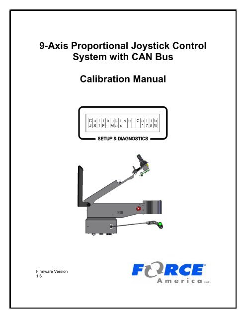
9-<strong>Axis</strong> Proportional Joystick Control<br />
System <strong>with</strong> <strong>CAN</strong> Bus<br />
<strong>Calibration</strong> <strong>Manual</strong><br />
C a l i b → L i v e C a l i b<br />
J S 1 F M a x * 7 5 %<br />
Firmware Version<br />
1.6
9-<strong>Axis</strong> <strong>Calibration</strong> <strong>Manual</strong><br />
Table of Contents<br />
Table of Contents<br />
Table of Contents ................................................................................................. i<br />
First Use Guide ................................................................................................... 1<br />
<strong>Calibration</strong> Menu ................................................................................................. 2<br />
To Enter the <strong>Calibration</strong> Menu .................................................................................................. 2<br />
ThumbCal Connection Port ...................................................................................................... 3<br />
iButton ......................................................................................................................................... 3<br />
Hardware Locations ................................................................................................................... 4<br />
<strong>Calibration</strong> Menu Navigation .................................................................................................... 5<br />
Trackback Line ......................................................................................................................... 5<br />
Menu Items Line ....................................................................................................................... 5<br />
Menu Movement ....................................................................................................................... 6<br />
Changing a Value ..................................................................................................................... 6<br />
Descriptions of <strong>Calibration</strong> Values .......................................................................................... 8<br />
Live Calib .................................................................................................................................. 8<br />
J1 ............................................................................................................................................ 11<br />
Cal ....................................................................................................................................... 11<br />
FW ................................................................................................................................... 11<br />
BK .................................................................................................................................... 11<br />
LT .................................................................................................................................... 12<br />
RT .................................................................................................................................... 12<br />
PB ....................................................................................................................................... 13<br />
LockTime ............................................................................................................................ 13<br />
Flt ........................................................................................................................................ 13<br />
Type ................................................................................................................................ 13<br />
Swch ................................................................................................................................ 13<br />
<strong>Axis</strong> .................................................................................................................................. 14<br />
Flt # ................................................................................................................................. 14<br />
Del ................................................................................................................................... 14<br />
A2D Counts......................................................................................................................... 14<br />
FW / BK ........................................................................................................................... 14<br />
LT / RT ............................................................................................................................ 15<br />
J2, J3, J4, J5 .......................................................................................................................... 15<br />
Freq Setup .............................................................................................................................. 15<br />
Ver .......................................................................................................................................... 15<br />
Master ................................................................................................................................. 15<br />
Slave ................................................................................................................................... 15<br />
i
9-<strong>Axis</strong> <strong>Calibration</strong> <strong>Manual</strong><br />
Table of Contents<br />
TransM ................................................................................................................................ 15<br />
Driver HW ........................................................................................................................... 16<br />
TransM HW ......................................................................................................................... 16<br />
Driver SN ............................................................................................................................ 16<br />
TransM SN .......................................................................................................................... 16<br />
Error Log ................................................................................................................................. 16<br />
OEM ....................................................................................................................................... 16<br />
Restore Defaults ..................................................................................................................... 17<br />
Save Calib .............................................................................................................................. 17<br />
To Exit the <strong>Calibration</strong> Menu .................................................................................................. 17<br />
Errors in <strong>Calibration</strong> ................................................................................................................ 17<br />
Error Conditions & Troubleshooting ............................................................... 18<br />
<strong>FORCE</strong> <strong>America</strong> Contact Information ............................................................. 19<br />
ii
9-<strong>Axis</strong> <strong>Calibration</strong> <strong>Manual</strong><br />
First Use Guide<br />
First Use Guide<br />
The first time you configure your 9-<strong>Axis</strong> system, you will need to complete the following steps:<br />
Step:<br />
Page Number:<br />
1. Configure your valve frequency. 15<br />
2. Calibrate your joystick Min and Max output<br />
levels using Live Calib or manual calibration.<br />
a. Live Calib<br />
b. <strong>Manual</strong> <strong>Calibration</strong><br />
3. Configure your pushbutton outputs, if<br />
necessary.<br />
8<br />
11<br />
13<br />
4. Configure your float outputs, if necessary. 13<br />
1
9-<strong>Axis</strong> <strong>Calibration</strong> <strong>Manual</strong><br />
<strong>Calibration</strong> Menu<br />
<strong>Calibration</strong> Menu<br />
To Enter the <strong>Calibration</strong> Menu<br />
Use a standard, non-crossover Ethernet cable to connect a 94069A001 ThumbCal into the<br />
Ethernet port on the side of the arm or switch base.<br />
Figure 1: 9-<strong>Axis</strong> Arm<br />
The <strong>Calibration</strong> Menu will appear on the Setup & Diagnostics screen. On a standard fit vehicle,<br />
the Setup & Diagnostics screen is located underneath the hinged arm rest. On a retrofitted<br />
vehicle, it is located on the circuit board inside the arm assembly. See Hardware Locations on<br />
page 4.<br />
For more information on hardware pinouts and<br />
connections, refer to the schematics in the<br />
9-<strong>Axis</strong> Binder.<br />
If you see the message “Replug for Calib” appear on your screen, as shown in Figure 2, the<br />
system has started or restarted while the ThumbCal device was plugged in. Simply disconnect<br />
and reconnect the ThumbCal device to the system in order to enter the <strong>Calibration</strong> Menu.<br />
R e p l u g f o r C a l i b<br />
Figure 2: Replug for Calib Screen<br />
2
9-<strong>Axis</strong> <strong>Calibration</strong> <strong>Manual</strong><br />
<strong>Calibration</strong> Menu<br />
ThumbCal Connection Port<br />
Connect the 94069A001 ThumbCal to the ThumbCal Connection Port using the included cable to<br />
open the <strong>Calibration</strong> Menu. The <strong>Calibration</strong> Menu will appear on the Setup & Diagnostics screen.<br />
iButton<br />
The iButton is a small, circular data storage device similar to a watch battery. The 9-<strong>Axis</strong> System<br />
stores all of its calibration settings on the iButton. The iButton is attached to the iButton Clip on<br />
the circuit board.<br />
iButton Clip<br />
If you receive a <strong>Calibration</strong> Error or an iButton Communication Error (see Error Conditions &<br />
Troubleshooting on page 18), you may need to replace your iButton. Order a replacement iButton<br />
from your local <strong>FORCE</strong> <strong>America</strong> Representative.<br />
To replace an iButton:<br />
STEP 1: Power down the 9-<strong>Axis</strong> System and disconnect it from power.<br />
STEP 2:<br />
STEP 3:<br />
STEP 4:<br />
STEP 5:<br />
STEP 6:<br />
Lift up the gold tab on the iButton Clip and gently slide the iButton out<br />
towards the Setup & Diagnostics Screen.<br />
Gently slide the replacement iButton into the iButton Clip.<br />
Reconnect the 9-<strong>Axis</strong> System to power and power it back up.<br />
Enter the <strong>Calibration</strong> Menu.<br />
Reconfigure and save your calibration settings to the new iButton.<br />
3
9-<strong>Axis</strong> <strong>Calibration</strong> <strong>Manual</strong><br />
<strong>Calibration</strong> Menu<br />
Hardware Locations<br />
On a standard fit vehicle, the Setup & Diagnostics screen is located underneath the hinged arm<br />
rest. The ThumbCal Connection Port is located on the side of the arm assembly. The iButton is<br />
located on the circuit board inside the arm assembly.<br />
Setup & Diagnostics Screen<br />
on standard fit systems<br />
iButton and ThumbCal<br />
Connection Port on standard<br />
fit systems<br />
Figure 3: Standard Fit 9-<strong>Axis</strong> System<br />
On a retrofitted vehicle, the Setup & Diagnostics screen, iButton, and ThumbCal Connection Port<br />
are located on the circuit board either inside the arm assembly or at the front of the switch base.<br />
Setup & Diagnostics Screen, iButton<br />
and ThumbCal Connection Port<br />
on retrofit systems<br />
Figure 4: Retrofit 9-<strong>Axis</strong> System<br />
4
9-<strong>Axis</strong> <strong>Calibration</strong> <strong>Manual</strong><br />
<strong>Calibration</strong> Menu<br />
<strong>Calibration</strong> Menu Navigation<br />
The <strong>Calibration</strong> Menu uses its “Never Lost Lite” menu system to ensure that navigating through<br />
the settings is quick and easy. “Never Lost Lite” uses both lines of the LCD. The top line of the<br />
LCD holds the Trackback Line and the bottom line holds the Menu Items, as shown in Figure 5.<br />
Trackback Line<br />
Menu Items<br />
C a l i b → J 1<br />
C a l<br />
Figure 5: The Layout of the <strong>Calibration</strong> Menu<br />
Trackback Line<br />
The Trackback Line shows your current location in the <strong>Calibration</strong> Menu. It will always list the<br />
submenus you traveled through to see your current screen. The submenu you are currently<br />
viewing will always be the furthest to the right in the Trackback. For example, in Figure 5, the user<br />
is editing the settings in the CALIB→J1 menu.<br />
Menu Items Line<br />
The Menu Items Line always displays your currently selected item, whether it’s a submenu, the<br />
name of a setting, or its value.<br />
When you enter a submenu, its name will move from the Menu Item line to the Trackback line.<br />
For example, Figure 6 will transition to Figure 7 when you enter the Live Calib submenu.<br />
C a l i B<br />
L i v e<br />
C a l i b<br />
Figure 6: Main Calib Menu<br />
C a l i b → L i v e<br />
← B a c k<br />
C a l i b<br />
Figure 7: Live Calib Submenu<br />
5
9-<strong>Axis</strong> <strong>Calibration</strong> <strong>Manual</strong><br />
<strong>Calibration</strong> Menu<br />
Menu Movement<br />
All actions <strong>with</strong>in the <strong>Calibration</strong> Menu are done using the ThumbCal (PN 94069A001). The<br />
ThumbCal is meant to be held in your left hand <strong>with</strong> the green encoder facing towards you.<br />
The table below lists the functions of the ThumbCal when in the <strong>Calibration</strong> Menu. Not all actions<br />
are available at all locations <strong>with</strong>in the menu.<br />
Action<br />
Twist Counter-Clockwise<br />
Twist Clockwise<br />
Push<br />
Function<br />
Scroll to previous menu item or submenu.<br />
Decrease a numeric value.<br />
Scroll to next menu item or submenu.<br />
Increase a numeric value.<br />
Enter submenu.<br />
Edit menu item.<br />
Confirm value.<br />
Return to previous menu.<br />
Changing a Value<br />
When changing a value in <strong>Calibration</strong>, the current set value will always be highlighted <strong>with</strong> an<br />
asterisk (*). In Figure 8, 35% is set as the Min.<br />
The ←BACK menu item will always return you to a previous submenu in the <strong>Calibration</strong> Menu.<br />
When editing a numeric value, such as Joystick 1’s Forward Min Output Percentage (Figure 8),<br />
the ←BACK menu item will appear when you are viewing the current set value.<br />
→ J 1 → C a l → F W → M i n<br />
← B A C K * 3 5 %<br />
Figure 8: Joystick Forward Min Set at 35%<br />
When you increase the numeric value but have not set it, the asterisk will disappear, as shown in<br />
Figure 9.<br />
→ J 1 → C a l → F W → M i n<br />
3 8 %<br />
Figure 9: Joystick Forward Min Increased to 38%, Not Set<br />
6
9-<strong>Axis</strong> <strong>Calibration</strong> <strong>Manual</strong><br />
<strong>Calibration</strong> Menu<br />
Select the value that is desired by pressing the pushbutton. An asterisk will appear next to the<br />
value indicating it is the new set value. See Figure 10.<br />
→ J 1 → C a l → F W → M i n<br />
← B a c k * 3 8 %<br />
Figure 10: Joystick Forward Min Increased to 38%,<br />
Set<br />
Once a numeric value is set using the ThumbCal’s pushbutton, the ←BACK menu will reappear<br />
and you can return to the previous submenu.<br />
When editing a selectable value, such as Joystick 1’s Pushbutton Output, the ←BACK menu item<br />
is always located at the end of the selectable options. See Figure 11.<br />
C a l i b → J 1 → P B<br />
← B a c k<br />
Figure 11: Joystick 1 Pushbutton Output Menu<br />
7
9-<strong>Axis</strong> <strong>Calibration</strong> <strong>Manual</strong><br />
<strong>Calibration</strong> Menu<br />
Descriptions of <strong>Calibration</strong> Values<br />
This section will describe each calibration value in the <strong>Calibration</strong> Menu in detail.<br />
WARNING<br />
<strong>Calibration</strong> Settings are not automatically saved when they<br />
are changed. Exiting the <strong>Calibration</strong> Menu <strong>with</strong>out using<br />
Save Calib will discard all changed calibration settings.<br />
Make sure to use Save Calib to save your settings.<br />
Live Calib<br />
Live <strong>Calibration</strong> is a new feature for dynamically calibrating (or nulling) an output’s minimum and<br />
maximum duty cycles. This guarantees maximum joystick precision when running outputs.<br />
Live Calib allows you to calibrate all of your joystick outputs from one menu location. Each<br />
direction on a joystick (forward, back, left, and right) can be individually calibrated.<br />
In Live Calib, all of the joystick functions are active so you can immediately see how your<br />
calibrations affect vehicle performance.<br />
When you enter Live Calib, you should see the following screen:<br />
C a l i b → L i v e<br />
← B a c k<br />
C a l i b<br />
Figure 12: Live Calib<br />
When you move a joystick slightly off-center, the system will allow you to change the minimum<br />
output duty cycle for the output associated <strong>with</strong> the movement direction. The Min output duty<br />
cycle can be adjusted between 0% and 90%. The default value is 35%.<br />
When you move a joystick over 50% off-center, the system will allow you to change the maximum<br />
output duty cycle for the output associated <strong>with</strong> the movement direction. The Max output duty<br />
cycle can be adjusted between 10% and 100%. The default value is 75%.<br />
Live Calib will automatically adjust the Min and the Max up or down so that they are at least 10%<br />
apart. For example, assume the Min is set at 35% and the Max is set at 75%. Increasing the Min<br />
to 90% will automatically increase the Max to 100%. Decreasing the Max to 10% will<br />
automatically decrease the Min to 0%.<br />
Rotating the ThumbCal’s encoder clockwise will increase the output duty<br />
cycle. The new value will be set immediately.<br />
Rotating the ThumbCal’s encoder counter-clockwise will decrease the<br />
output duty cycle. The new value will be set immediately.<br />
Press the ThumbCal’s pushbutton at any time to return to the <strong>Calibration</strong><br />
Menu.<br />
8
9-<strong>Axis</strong> <strong>Calibration</strong> <strong>Manual</strong><br />
<strong>Calibration</strong> Menu<br />
Live Calib Error Conditions<br />
If a joystick is off-center when you enter Live Calib, the Setup & Diagnostics screen will display:<br />
C a l i b → L i v e C a l i b<br />
C e n t e r J o y s t i c k s<br />
Figure 13: Live Calib - Joystick Off Center Error Upon Entry<br />
When this error occurs, the joystick functions will no longer operate and the min and max settings<br />
cannot be calibrated until all joysticks have been centered for 3 seconds.<br />
If multiple joysticks are moved off-center at the same time, the Setup & Diagnostics screen will<br />
display:<br />
C a l i b → L i v e C a l i b<br />
2 J S O f f C e n t e r<br />
Figure 14: Live Calib - Multiple Joysticks Off Center Error<br />
When this error occurs, the joystick functions will no longer operate and the min and max settings<br />
cannot be changed until only one joystick is off center.<br />
9
9-<strong>Axis</strong> <strong>Calibration</strong> <strong>Manual</strong><br />
<strong>Calibration</strong> Menu<br />
To Live Calib a joystick’s MIN value:<br />
STEP 1: Move a single joystick slightly off-center in the direction you want to calibrate.<br />
For example, to calibrate the MIN for the JS1F output, move Joystick 1<br />
forward slightly.<br />
STEP 2:<br />
The Setup & Diagnostics screen will display:<br />
C a l i b → L i v e C a l i b<br />
J S 1 F M i n 4 0 %<br />
Figure 15: Live Calibrating Joystick 1 Forward Min<br />
STEP 3:<br />
STEP 4:<br />
STEP 5:<br />
While holding the joystick in place, scroll the ThumbCal clockwise or counterclockwise<br />
to increase or decrease the MIN value. For maximum precision,<br />
set the Min so that the output runs at the slowest rate possible <strong>with</strong>out<br />
stopping.<br />
When the calibrated value is reached, return Joystick 1 to the center position.<br />
The value will be automatically set.<br />
When finished, return to the Main <strong>Calibration</strong> Menu and save the calibration<br />
settings using Save Calib.<br />
To Live Calib a joystick’s MAX value:<br />
STEP 7: Move a single joystick off-center to its maximum range in the direction you<br />
want to calibrate. For example, to calibrate the MAX for the JS1F output,<br />
move Joystick 1 to its maximum forward range.<br />
STEP 8:<br />
The Setup & Diagnostics screen will display:<br />
C a l i b → L i v e C a l i b<br />
J S 1 F M a x 9 0 %<br />
Figure 16: Live Calibrating Joystick 1 Forward Max<br />
STEP 9:<br />
STEP 10:<br />
STEP 11:<br />
While holding the joystick in place, scroll the ThumbCal clockwise or counterclockwise<br />
to increase or decrease the MIN value. For maximum precision,<br />
set the Max so that the output runs at its maximum speed at full joystick<br />
travel.<br />
When the calibrated value is reached, return Joystick 1 to the center position.<br />
The value will be automatically set.<br />
When finished, return to the Main <strong>Calibration</strong> Menu and save the calibration<br />
settings using Save Calib.<br />
10
9-<strong>Axis</strong> <strong>Calibration</strong> <strong>Manual</strong><br />
<strong>Calibration</strong> Menu<br />
J1<br />
The J1 menu allows you to configure settings for Joystick 1. These settings include minimum and<br />
maximum duty cycle settings, pushbutton settings, and float settings.<br />
Cal<br />
The Cal menu contains settings for adjusting the minimum and maximum values on<br />
Joystick 1 outputs. The Min and Max settings are defined per movement.<br />
FW<br />
The FW menu contains the Min and Max settings for Joystick 1 forward<br />
movement. If Joystick 1 does not have a forward/backward axis, this menu will<br />
not be visible.<br />
Min<br />
The Min menu item allows you to change the minimum output duty cycle<br />
in percent for the JS1F output. The Min output duty cycle can be<br />
adjusted between 0% and 90% output. The default value is 35%.<br />
If JS1F was calibrated using Live Calib, this value will match the value<br />
set in Live Calib.<br />
If the minimum value is set above the maximum value, the maximum will<br />
shift to be at least 10% above the minimum.<br />
Max<br />
The Max menu item allows you to change the maximum output duty<br />
cycle in percent for the JS1F output. The Max output duty cycle can be<br />
adjusted between 10% and 100% output. The default value is 75%.<br />
If JS1F was calibrated using Live Calib, this value will match the value<br />
set in Live Calib.<br />
If the maximum value is set below the minimum value, the minimum will<br />
shift to be at least 10% below the maximum.<br />
BK<br />
The BK menu contains the Min and Max settings for Joystick 1’s backward<br />
movement. If Joystick 1 does not have a forward/backward axis, this menu will<br />
not be visible.<br />
Min<br />
The Min menu item allows you to change the minimum output duty cycle<br />
in percent for the JS1B output. The Min output duty cycle can be<br />
adjusted between 0% and 90% output. The default value is 35%.<br />
If JS1B was calibrated using Live Calib, this value will match the value<br />
set in Live Calib.<br />
If the minimum value is set above the maximum value, the maximum will<br />
shift to be at least 10% above the minimum.<br />
Max<br />
The Max menu item allows you to change the maximum output duty<br />
cycle in percent for the JS1B output. The Max output duty cycle can be<br />
adjusted between 10% and 100% output. The default value is 75%.<br />
11
9-<strong>Axis</strong> <strong>Calibration</strong> <strong>Manual</strong><br />
<strong>Calibration</strong> Menu<br />
If JS1B was calibrated using Live Calib, this value will match the value<br />
set in Live Calib.<br />
If the maximum value is set below the minimum value, the minimum will<br />
shift to be at least 10% below the maximum.<br />
LT<br />
The LT menu contains the Min and Max settings for Joystick 1’s left movement. If<br />
Joystick 1 does not have a left/right axis, this menu will not be visible.<br />
Min<br />
The Min menu item allows you to change the minimum output duty cycle<br />
in percent for the JS1L output. The Min output duty cycle can be<br />
adjusted between 0% and 90% output. The default value is 35%.<br />
If JS1L was calibrated using Live Calib, this value will match the value<br />
set in Live Calib.<br />
If the minimum value is set above the maximum value, the maximum will<br />
shift to be at least 10% above the minimum.<br />
Max<br />
The Max menu item allows you to change the maximum output duty<br />
cycle in percent for the JS1L output. The Max output duty cycle can be<br />
adjusted between 10% and 100% output. The default value is 75%.<br />
If JS1L was calibrated using Live Calib, this value will match the value<br />
set in Live Calib.<br />
If the maximum value is set below the minimum value, the minimum will<br />
shift to be at least 10% below the maximum.<br />
RT<br />
The RT menu contains the Min and Max settings for Joystick 1’s right movement.<br />
If Joystick 1 does not have a left/right axis, this menu will not be visible.<br />
Min<br />
The Min menu item allows you to change the minimum output duty cycle<br />
in percent for the JS1R output. The Min output duty cycle can be<br />
adjusted between 0% and 90% output. The default value is 35%.<br />
If JS1R was calibrated using Live Calib, this value will match the value<br />
set in Live Calib.<br />
If the minimum value is set above the maximum value, the maximum will<br />
shift to be at least 10% above the minimum.<br />
Max<br />
The Max menu item allows you to change the maximum output duty<br />
cycle in percent for the JS1R output. The Max output duty cycle can be<br />
adjusted between 10% and 100% output. The default value is 75%.<br />
If JS1R was calibrated using Live Calib, this value will match the value<br />
set in Live Calib.<br />
12
9-<strong>Axis</strong> <strong>Calibration</strong> <strong>Manual</strong><br />
<strong>Calibration</strong> Menu<br />
If the maximum value is set below the minimum value, the minimum will<br />
shift to be at least 10% below the maximum.<br />
PB<br />
The PB menu item allows you to set the output or function that runs when Joystick 1’s<br />
pushbutton is pressed. If Joystick 1 does not have a pushbutton, this menu will not be<br />
visible.<br />
The available options are Disabled, Interlock, Blast, Standby, Vibrator, Gen1, and Gen2.<br />
The default value is Disabled.<br />
Disabled<br />
Interlock<br />
Blast<br />
Standby<br />
Vibrator<br />
Gen1<br />
Gen2<br />
The pushbutton shall do nothing.<br />
The pushbutton shall activate the joystick so<br />
movement runs a function. The joystick function will<br />
only operate if the pushbutton is pressed.<br />
The pushbutton shall activate the Blast output on an<br />
attached spreader control, if equipped.<br />
The pushbutton shall activate the Standby output on<br />
an attached spreader control, if equipped.<br />
The pushbutton shall activate the Vibrator output on<br />
an attached spreader control, if equipped.<br />
The pushbutton shall activate the Generic 1 output.<br />
The pushbutton shall activate the Generic 2 output.<br />
LockTime<br />
The LockTime menu item allows you to set the interlock timeout for all joysticks that have<br />
their pushbutton configured as Interlock.<br />
If LockTime is set to zero, releasing the joystick’s pushbutton will immediately deactivate<br />
the interlock (momentary interlock). Otherwise, the interlock will remain active until the<br />
joystick has been in the center position for the number of seconds equal to LockTime.<br />
The available options are from 0 to 90 seconds. The default value is 0 seconds.<br />
Flt<br />
The Flt menu contains settings for Joystick 1’s float. These settings include float type,<br />
switch, axis, secondary output, and delay settings.<br />
Type<br />
The Type menu item allows you to set the type of float that is associated <strong>with</strong><br />
Joystick 1.<br />
The available options are Single-Acting, Dual-Acting, or None. The default value<br />
is None. If the type is set to None, the Swch, <strong>Axis</strong>, Flt #, and Del menus will not<br />
appear.<br />
Users <strong>with</strong> Power Float and Blade Saver should set Type to Dual-Acting.<br />
Swch<br />
The Swch menu item allows you to choose whether or not the float is always on<br />
or controlled by an external switch. If a switch is not installed, the float is<br />
considered always on.<br />
Refer to your order documentation to determine if your vehicle has a float enable<br />
switch, and if so, which input it is connected to. Set Flt # to this input.<br />
13
9-<strong>Axis</strong> <strong>Calibration</strong> <strong>Manual</strong><br />
<strong>Calibration</strong> Menu<br />
The available options are Yes and No. The default value is No.<br />
<strong>Axis</strong><br />
The axis menu item allows you to choose which direction of Joystick 1 activates<br />
the float. The axis opposite of this value shall automatically be set to deactivate<br />
the float.<br />
The available options are FW, BK, LT, and RT. The default value is FW.<br />
Flt #<br />
The Flt # menu item allows you to choose which external output runs when the<br />
float is activated and which external input turns the float on and off when a switch<br />
is enabled. The Flt # menu item will only be visible if the Type menu item is set to<br />
Dual Acting or the Swch menu item is set to Yes.<br />
The available options are None, Float 1, Float 2, Float 3, and Float 4. These<br />
directly correspond to the Float 1, Float 2, Float 3, and Float 4 pins on the<br />
94065A001 Driver Board’s float connector. The default value is None.<br />
Del<br />
The Del menu item allows you to set an optional 3 second delay in activating the<br />
float. When this is set to Yes, the driver must hold the joystick in the appropriate<br />
direction for at least 3 seconds before the float is activated.<br />
The available options are Yes and No. The default value is No.<br />
A2D Counts<br />
The A2D Counts menu item provides diagnostic tools used to show the current Analog to<br />
Digital Counts coming from Joystick 1 into the 94066A001 Transmitter Board.<br />
This menu and its submenus are meant to be used <strong>with</strong> the help and support of a<br />
<strong>FORCE</strong> <strong>America</strong> Representative.<br />
FW / BK<br />
The FW / BK menu item shows the A2D Counts for the forward/backward axis of<br />
the joystick. Pressing the ThumbCal’s pushbutton will return you to the A2D<br />
Counts menu.<br />
C a l i b → J 1 → A 2 D C t s<br />
F W / B K Y Y Y Y / Z Z Z Z<br />
Figure 17: FW / BK A2D Counts<br />
YYYY shows the counts coming from Joystick 1’s forward/backward<br />
non-inverting input.<br />
ZZZZ shows the counts coming from Joystick 1’s forward/backward inverting<br />
input.<br />
14
9-<strong>Axis</strong> <strong>Calibration</strong> <strong>Manual</strong><br />
<strong>Calibration</strong> Menu<br />
LT / RT<br />
The LT / RT menu item shows the A2D Counts for the left/right axis of the<br />
joystick. Pressing the ThumbCal’s pushbutton will return you to the A2D Counts<br />
menu.<br />
C a l i b → J 1 → A 2 D C t s<br />
L T / R T Y Y Y Y / Z Z Z Z<br />
Figure 18: LT / RT A2D Counts<br />
YYYY shows the counts coming from Joystick 1’s left/right non-inverting input.<br />
ZZZZ shows the counts coming from Joystick 1’s left/right inverting input.<br />
J2, J3, J4, J5<br />
The J2, J3, J4, and J5 menus allow you to configure settings for Joysticks 2, 3, 4, and 5. These<br />
settings are identical to the Joystick 1 settings, beginning on page 11.<br />
Freq Setup<br />
The Frequency Setup menu item allows you to select the frequency at which to run the valve<br />
outputs. This frequency will vary depending on the brand and type of valve being used. See your<br />
valve manufacturer’s documentation for the recommended operating frequency.<br />
The available options are 50 Hz and 125Hz. The default value is 50 Hz.<br />
Ver<br />
The versions submenu allows you to see the current revision of firmware on the Driver Board’s<br />
master processor, slave processor, and the Transmitter Board’s processor. The versions<br />
submenu also allows you to see the hardware revision and serial numbers for the Driver Board<br />
and the Transmitter Board.<br />
Master<br />
The Master menu item shows the version number of the firmware on the driver board’s<br />
master processor.<br />
Slave<br />
The Slave menu item shows the version number of the firmware on the driver board’s<br />
slave processor.<br />
TransM<br />
The TransM menu item shows the version number of the firmware on the MPJC<br />
transmitter board’s processor.<br />
15
9-<strong>Axis</strong> <strong>Calibration</strong> <strong>Manual</strong><br />
<strong>Calibration</strong> Menu<br />
Driver HW<br />
The Driver HW menu item shows the revision number of the driver board PCB.<br />
TransM HW<br />
The TransM HW menu item shows the revision number of the MPJC transmitter board<br />
PCB.<br />
Driver SN<br />
The Driver SN menu item shows the serial number of the driver board.<br />
TransM SN<br />
The TransM SN menu item shows the serial number of the MPJC transmitter board.<br />
Error Log<br />
The Error Log allows you to see how many times a specific error has occurred since startup. It<br />
records up to 99 instances of each error condition. The Error Log is cleared when the system is<br />
powered off.<br />
C a l i b → E r r o r L o g<br />
T r a n s M C o m m 9 9<br />
Figure 19: Error Log showing 99 Transmitter Communication Errors<br />
All of the system-wide errors are displayed first:<br />
TransM Comm<br />
Slave Comm<br />
ESTOP<br />
Overvoltage<br />
Undervoltage<br />
<strong>Calibration</strong><br />
iButton<br />
LCD Comm<br />
ESTOP Wiring<br />
For more information on error<br />
conditions, see Troubleshooting<br />
and Error Codes on page 18.<br />
All of the valve, float, and joystick-specific errors are categorized on a per-joystick basis. Beneath<br />
the J1, J2, J3, J4, and J5 menus are the following error logs:<br />
JSN Valve<br />
JSN Float<br />
JSN Output<br />
JSN Integ<br />
JSN Hi Range<br />
JSN Lo Range<br />
JSN Norm<br />
JSN Center<br />
JSN Stuck PB<br />
OEM<br />
The OEM menu contains system-wide hardware configuration settings that are only available to<br />
<strong>FORCE</strong> <strong>America</strong> Representatives.<br />
16
9-<strong>Axis</strong> <strong>Calibration</strong> <strong>Manual</strong><br />
<strong>Calibration</strong> Menu<br />
Restore Defaults<br />
The Restore Defaults menu item changes all calibration menu items except the OEM settings<br />
back to their factory-supplied defaults. This can be useful when a valve needs to be recalibrated<br />
and you need to start from a known value. Upon restoring defaults, you will be returned to the<br />
<strong>Calibration</strong> Menu.<br />
Using the Restore Defaults menu item does not save the restored defaults to the iButton. Make<br />
sure you save your calibration settings using Save Calib in order for the restored defaults to take<br />
effect.<br />
Save Calib<br />
The Save Calib menu item saves all changed menu item values to the iButton storage device.<br />
Upon saving, you will be returned to the <strong>Calibration</strong> Menu.<br />
WARNING<br />
Removing the ThumbCal from the system<br />
<strong>with</strong>out using Save Calib will discard all<br />
changed calibration settings.<br />
To Exit the <strong>Calibration</strong> Menu<br />
Exit the <strong>Calibration</strong> Menu by disconnecting the 94069A001 ThumbCal from the Ethernet port on<br />
the arm base.<br />
WARNING<br />
Exiting the <strong>Calibration</strong> Menu <strong>with</strong>out using<br />
Save Calib will discard all changed calibration<br />
settings.<br />
Errors in <strong>Calibration</strong><br />
Only critical, system-wide errors can occur in <strong>Calibration</strong>:<br />
• Transmitter Communication Error<br />
• Slave PIC Communication Error<br />
• Emergency Stop Warning<br />
• Power Overvoltage Error<br />
• Power Undervoltage Error<br />
• LCD Communication Error<br />
• Invalid ESTOP Wiring Error<br />
• <strong>Calibration</strong> Error<br />
• iButton Communication Error<br />
When one of these errors occurs, you will be exited from <strong>Calibration</strong> and any changes you made<br />
that were not saved will be erased.<br />
For more information and solutions for each error condition, see Error Conditions &<br />
Troubleshooting on page 18.<br />
17
9-<strong>Axis</strong> <strong>Calibration</strong> <strong>Manual</strong><br />
<strong>Calibration</strong> Menu<br />
Error Conditions & Troubleshooting<br />
If an error occurs during system operation, use the following table to determine the cause and<br />
solution. A “long” beep is a tone that lasts for 2 seconds, followed by 2 seconds of silence. A<br />
short beep is a tone that lasts for ½ second, followed by ½ second of silence.<br />
Number of Beeps Possible Cause Solution<br />
Solid<br />
<strong>CAN</strong> Communication between the driver<br />
board and transmitter board has been lost.<br />
<strong>CAN</strong> Communication between the driver<br />
board master processor and the slave<br />
processor has been lost.<br />
Verify the integrity of the <strong>CAN</strong><br />
cable connecting the<br />
94065A001 driver board to<br />
the 94066A001 transmitter<br />
board.<br />
Verify the integrity of the<br />
94065A001 driver board.<br />
1 Long The Emergency STOP (ESTOP) switch<br />
has been activated.<br />
1 Short The 9-<strong>Axis</strong> system is receiving too much<br />
voltage.<br />
The 9-<strong>Axis</strong> system is receiving too little<br />
voltage.<br />
3 Short The 9-<strong>Axis</strong> system has corrupted<br />
calibration settings.<br />
The 9-<strong>Axis</strong> system cannot communicate<br />
<strong>with</strong> the calibration settings iButton.<br />
5 Short A short or an open circuit has been<br />
detected on the joystick output that is<br />
blinking.<br />
A short or an open circuit has been<br />
detected on the pushbutton output that is<br />
blinking.<br />
7 Short The joystick that is blinking is operating<br />
outside of its acceptable range.<br />
9 Short The joystick was detected off-center at<br />
startup.<br />
The joystick’s pushbutton was detected<br />
pressed on startup.<br />
11 Short The 9-<strong>Axis</strong> system cannot communicate<br />
<strong>with</strong> the Setup & Diagnostics screen.<br />
13 Short The Emergency Stop Switch is miswired<br />
and will not function properly.<br />
Twist the ESTOP switch to<br />
deactivate the Emergency<br />
Stop.<br />
Verify the integrity of the<br />
vehicle’s electrical system.<br />
Verify the integrity of the<br />
vehicle’s electrical system.<br />
Verify the integrity of the<br />
iButton and iButton interface<br />
on the 94065A001 driver<br />
board.<br />
Verify the integrity of the<br />
outputs and wiring.<br />
Verify the integrity of the<br />
outputs and wiring.<br />
Contact a <strong>FORCE</strong> <strong>America</strong><br />
Representative for a<br />
replacement joystick.<br />
Verify that the joystick is not<br />
off-center.<br />
Verify that the joystick’s<br />
pushbutton is not pressed.<br />
Verify the integrity of the<br />
94065A001 driver board.<br />
Verify the wiring of the<br />
Emergency Stop Switch.<br />
18
9-<strong>Axis</strong> <strong>Calibration</strong> <strong>Manual</strong><br />
<strong>FORCE</strong> <strong>America</strong> Contact Information<br />
<strong>FORCE</strong> <strong>America</strong> Contact Information<br />
Should you encounter problems <strong>with</strong> your 9-<strong>Axis</strong> System that are not documented in this<br />
<strong>Calibration</strong> <strong>Manual</strong> or the 9-<strong>Axis</strong> Proportional Joystick Control System <strong>with</strong> <strong>CAN</strong> Bus Operation<br />
<strong>Manual</strong> (M0105), please contact your local <strong>FORCE</strong> <strong>America</strong> Sales Representative for assistance.<br />
For company and product information, please contact <strong>FORCE</strong> <strong>America</strong> at:<br />
Phone: 1-888-99<strong>FORCE</strong> (1-888-993-6723)<br />
Website: http://www.forceamerica.com<br />
E-mail: info@forceamerica.com<br />
19
Document No: M0106-B<br />
Released: 02/22/2010<br />
Copyright © 2010 <strong>FORCE</strong> <strong>America</strong> Inc.