

High-Voltage Circuit-Breakers 3AP1/2 72.5 kV up to 550 kV - Siemens
High-Voltage Circuit-Breakers 3AP1/2 72.5 kV up to 550 kV - Siemens
High-Voltage Circuit-Breakers 3AP1/2 72.5 kV up to 550 kV - Siemens

You also want an ePaper? Increase the reach of your titles
YUMPU automatically turns print PDFs into web optimized ePapers that Google loves.
The Control<br />
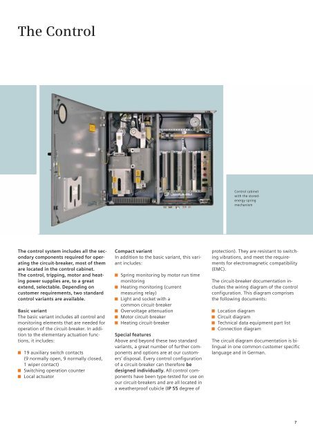
Control cabinet<br />
with the s<strong>to</strong>redenergy<br />
spring<br />
mechanism<br />
The control system includes all the secondary<br />
components required for operating<br />
the circuit-breaker, most of them<br />
are located in the control cabinet.<br />
The control, tripping, mo<strong>to</strong>r and heating<br />
power s<strong>up</strong>plies are, <strong>to</strong> a great<br />
extend, selectable. Depending on<br />
cus<strong>to</strong>mer requirements, two standard<br />
control variants are available.<br />
Basic variant<br />
The basic variant includes all control and<br />
moni<strong>to</strong>ring elements that are needed for<br />
operation of the circuit-breaker. In addition<br />
<strong>to</strong> the elementary actuation functions,<br />
it includes:<br />
19 auxiliary switch contacts<br />
(9 normally open, 9 normally closed,<br />
1 wiper contact)<br />
Switching operation counter<br />
Local actua<strong>to</strong>r<br />
Compact variant<br />
In addition <strong>to</strong> the basic variant, this variant<br />
includes:<br />
Spring moni<strong>to</strong>ring by mo<strong>to</strong>r run time<br />
moni<strong>to</strong>ring<br />
Heating moni<strong>to</strong>ring (current<br />
measuring relay)<br />
Light and socket with a<br />
common circuit-breaker<br />
Overvoltage attenuation<br />
Mo<strong>to</strong>r circuit-breaker<br />
Heating circuit-breaker<br />
Special features<br />
Above and beyond these two standard<br />
variants, a great number of further components<br />
and options are at our cus<strong>to</strong>mers’<br />
disposal. Every control configuration<br />
of a circuit-breaker can therefore be<br />
designed individually. All control components<br />
have been type-tested for use on<br />
our circuit-breakers and are all located in<br />
a weatherproof cubicle (IP 55 degree of<br />
protection). They are resistant <strong>to</strong> switching<br />
vibrations, and meet the requirements<br />
for electromagnetic compatibility<br />
(EMC).<br />
The circuit-breaker documentation includes<br />
the wiring diagram of the control<br />
configuration. This diagram comprises<br />
the following documents:<br />
Location diagram<br />
<strong>Circuit</strong> diagram<br />
Technical data equipment part list<br />
Connection diagram<br />
The circuit diagram documentation is bilingual<br />
in one common cus<strong>to</strong>mer specific<br />
language and in German.<br />
7


