Introduction 0-7803-8883-6105/$20.00 ©2005 IEEE
Introduction 0-7803-8883-6105/$20.00 ©2005 IEEE
Introduction 0-7803-8883-6105/$20.00 ©2005 IEEE
You also want an ePaper? Increase the reach of your titles
YUMPU automatically turns print PDFs into web optimized ePapers that Google loves.
Feedback Antenna Oscillator Design<br />
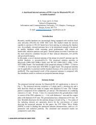
The proposed AIA configuration is shown in Fig. 1. The oscillator contains an<br />
amplifier and an electromagnetically coupling T-shaped microstrip-line-fed slot<br />
antenna. Extra microstrip lines placed both opposite sides of the rectangular slot are<br />
required to adjust the loop phase (multiple of 2x at the operating frequency) for<br />
oscillation. In order to maintain the constant load impedance at each antenna port, the<br />
proper input and output matching circuit was designed. The oscillator was fabricated<br />
on the substrate with thickness of 0.508 mm and relative dielectric constant (&,) of 3.0.<br />
For an operating frequency of 10 GHz, we let the slot has a size L x W of 4.3 x 10.8<br />
mm2 with an optimized T-microstip line length wi = 8.8 mm and the width of 1.56 mm<br />
which is the same as the width of 50 Q2 microstrip line, and then vary the distances li<br />
and l. The results come out to be l = 0.2 mm and lg = 1.04 mm. With these parameters,<br />
a two-port T-shaped microstrip-line-fed slot antenna is fabricated and measured.<br />
Fig. 2 shows the measured and simulated results of the S-parameters for the two-port<br />
slot antenna. At the center frequency of 10 GHz, the measured return loss of the<br />
feeding is approximately -34 dB and the coupling power is -3.6 dB. The impedance<br />
bandwidth (2:1 VSWR) is 27 %, which show a wide bandwidth. It seen that the<br />
measured results agree very well with those of the simulations.<br />
Measurement<br />
A bias condition for the oscillator with an ATF-13786 GaAs MESFET is VDS = 3 V<br />
and VGs = 0.5 V with a drain current (IDS) of 30 mA, and the oscillator is driven by the<br />
self-biasing technique.<br />
Fig. 3 shows the radiated output power from the fabricated feedback antenna<br />
oscillator measured in anechoic chamber. This oscillation frequency is measured at<br />
10.05 GHz, which is 0.5 % close to the frequency of 10 GHz. The output power is<br />
measured about -20.75 dBm using an Agilent E4440A spectrum analyzer and a hom<br />
antenna (Gain = 16.5 dBi) as a reference antenna away from a distance of 1.2 m. An<br />
EIRP (Effective Isotropic Radiated Power) correspond to the above data is 37.79 mW.<br />
The simulated and measured radiation pattems for x-z plane and y-z plane are shown<br />
in Fig. 4. In order to maintain the same measuring environment, the simulated radiation<br />
patterns are calculated by using the gap source technique, in the commercial EM<br />
simulator HFSS, considering the complete feedback active antenna which has same<br />
layout except an active transistor. Both of the radiation patterns are similar to those of<br />
the x-directed dipole antenna. The received cross-polarizations in the x-z plane and y-z<br />
plane of the AIA are approximately -20 dB and -15 dB lower than the maximum copolarized<br />
radiation, respectively. The measured co-polarized radiation patterns in the x-<br />
z and y-z plane have a similar trend with those of the simulated results.<br />
Conclusion<br />
In this paper, the feedback antenna oscillator using the T-shaped microstrip-line-fed<br />
slot antenna is proposed. The fabricated active antenna is investigated with the<br />
comparison of the measured and simulated results. The oscillator antenna achieves an<br />
214


