HIGH ASPECT RATIO DEEP SILICON ETCHING
HIGH ASPECT RATIO DEEP SILICON ETCHING
HIGH ASPECT RATIO DEEP SILICON ETCHING

Create successful ePaper yourself
Turn your PDF publications into a flip-book with our unique Google optimized e-Paper software.
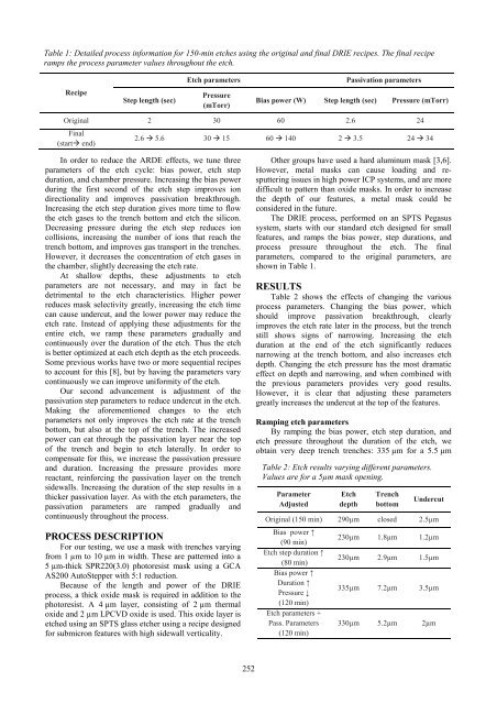
Table 1: Detailed process information for 150-min etches using the original and final DRIE recipes. The final recipe<br />
ramps the process parameter values throughout the etch.<br />
Etch parameters<br />
Passivation parameters<br />
Recipe<br />
Step length (sec)<br />
Pressure<br />
(mTorr)<br />
Bias power (W) Step length (sec) Pressure (mTorr)<br />
Original 2 30 60 2.6 24<br />
Final<br />
(start end)<br />
2.6 5.6 30 15 60 140 2 3.5 24 34<br />
In order to reduce the ARDE effects, we tune three<br />
parameters of the etch cycle: bias power, etch step<br />
duration, and chamber pressure. Increasing the bias power<br />
during the first second of the etch step improves ion<br />
directionality and improves passivation breakthrough.<br />
Increasing the etch step duration gives more time to flow<br />
the etch gases to the trench bottom and etch the silicon.<br />
Decreasing pressure during the etch step reduces ion<br />
collisions, increasing the number of ions that reach the<br />
trench bottom, and improves gas transport in the trenches.<br />
However, it decreases the concentration of etch gases in<br />
the chamber, slightly decreasing the etch rate.<br />
At shallow depths, these adjustments to etch<br />
parameters are not necessary, and may in fact be<br />
detrimental to the etch characteristics. Higher power<br />
reduces mask selectivity greatly, increasing the etch time<br />
can cause undercut, and the lower power may reduce the<br />
etch rate. Instead of applying these adjustments for the<br />
entire etch, we ramp these parameters gradually and<br />
continuously over the duration of the etch. Thus the etch<br />
is better optimized at each etch depth as the etch proceeds.<br />
Some previous works have two or more sequential recipes<br />
to account for this [8], but by having the parameters vary<br />
continuously we can improve uniformity of the etch.<br />
Our second advancement is adjustment of the<br />
passivation step parameters to reduce undercut in the etch.<br />
Making the aforementioned changes to the etch<br />
parameters not only improves the etch rate at the trench<br />
bottom, but also at the top of the trench. The increased<br />
power can eat through the passivation layer near the top<br />
of the trench and begin to etch laterally. In order to<br />
compensate for this, we increase the passivation pressure<br />
and duration. Increasing the pressure provides more<br />
reactant, reinforcing the passivation layer on the trench<br />
sidewalls. Increasing the duration of the step results in a<br />
thicker passivation layer. As with the etch parameters, the<br />
passivation parameters are ramped gradually and<br />
continuously throughout the process.<br />
PROCESS DESCRIPTION<br />
For our testing, we use a mask with trenches varying<br />
from 1 µm to 10 µm in width. These are patterned into a<br />
5 µm-thick SPR220(3.0) photoresist mask using a GCA<br />
AS200 AutoStepper with 5:1 reduction.<br />
Because of the length and power of the DRIE<br />
process, a thick oxide mask is required in addition to the<br />
photoresist. A 4 µm layer, consisting of 2 µm thermal<br />
oxide and 2 µm LPCVD oxide is used. This oxide layer is<br />
etched using an SPTS glass etcher using a recipe designed<br />
for submicron features with high sidewall verticality.<br />
Other groups have used a hard aluminum mask [3,6].<br />
However, metal masks can cause loading and resputtering<br />
issues in high power ICP systems, and are more<br />
difficult to pattern than oxide masks. In order to increase<br />
the depth of our features, a metal mask could be<br />
considered in the future.<br />
The DRIE process, performed on an SPTS Pegasus<br />
system, starts with our standard etch designed for small<br />
features, and ramps the bias power, step durations, and<br />
process pressure throughout the etch. The final<br />
parameters, compared to the original parameters, are<br />
shown in Table 1.<br />
RESULTS<br />
Table 2 shows the effects of changing the various<br />
process parameters. Changing the bias power, which<br />
should improve passivation breakthrough, clearly<br />
improves the etch rate later in the process, but the trench<br />
still shows signs of narrowing. Increasing the etch<br />
duration at the end of the etch significantly reduces<br />
narrowing at the trench bottom, and also increases etch<br />
depth. Changing the etch pressure has the most dramatic<br />
effect on depth and narrowing, and when combined with<br />
the previous parameters provides very good results.<br />
However, it is clear that adjusting these parameters<br />
greatly increases the undercut at the top of the features.<br />
Ramping etch parameters<br />
By ramping the bias power, etch step duration, and<br />
etch pressure throughout the duration of the etch, we<br />
obtain very deep trench trenches: 335 µm for a 5.5 µm<br />
Table 2: Etch results varying different parameters.<br />
Values are for a 5µm mask opening.<br />
Parameter<br />
Adjusted<br />
Etch<br />
depth<br />
Trench<br />
bottom<br />
Undercut<br />
Original (150 min) 290µm closed 2.5µm<br />
Bias power ↑<br />
(90 min)<br />
230µm 1.8µm 1.2µm<br />
Etch step duration ↑<br />
(80 min)<br />
230µm 2.9µm 1.5µm<br />
Bias power ↑<br />
Duration ↑<br />
Pressure ↓<br />
335µm 7.2µm 3.5µm<br />
(120 min)<br />
Etch parameters +<br />
Pass. Parameters<br />
(120 min)<br />
330µm 5.2µm 2µm<br />
252


![[Sample B: Approval/Signature Sheet]](https://img.yumpu.com/34084789/1/190x245/sample-b-approval-signature-sheet.jpg?quality=85)