CKD series FCM small size flow controller
CKD series FCM small size flow controller
CKD series FCM small size flow controller

You also want an ePaper? Increase the reach of your titles
YUMPU automatically turns print PDFs into web optimized ePapers that Google loves.
<strong>FCM</strong> Series<br />
Refrigerating<br />
type dryer<br />
Desiccant<br />
type dryer<br />
High polymer<br />
membrane<br />
dryer<br />
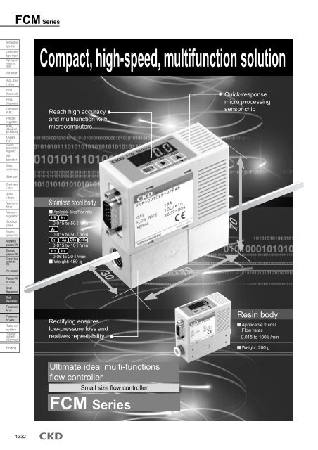
Compact, high-speed, multifunction solution<br />
Air filter<br />
Auto. drain<br />
/ others<br />
F.R.L.<br />
(Module unit)<br />
F.R.L.<br />
(Separate)<br />
Compact<br />
F.R.<br />
Precise<br />
regulator<br />
F.R.L.<br />
(Related<br />
products)<br />
Clean<br />
F.R.<br />
Electro<br />
pneumatic<br />
regulator<br />
Air<br />
booster<br />
Speed<br />
control valve<br />
Silencer<br />
Check valve<br />
/ others<br />
Joint<br />
/ tube<br />
Vacuum<br />
filter<br />
Vacuum<br />
regulator<br />
Suction<br />
plate<br />
Magnetic<br />
spring buffer<br />
Mechanical<br />
pressure SW<br />
Electronic<br />
pressure SW<br />
Contact / close<br />
contact conf.<br />
SW<br />
Air sensor<br />
Pressure SW<br />
for coolant<br />
Small<br />
<strong>flow</strong> sensor<br />
Small<br />
<strong>flow</strong> <strong>controller</strong><br />
Flow sensor<br />
for air<br />
Flow sensor<br />
for water<br />
Total air<br />
system<br />
Total air<br />
system<br />
(Gamma)<br />
Ending<br />
Reach high accuracy<br />
and multifunction with<br />
microcomputers<br />
Stainless steel body<br />
Applicable fluids/Flow rates<br />
0.015 to 50 /min<br />
0.015 to 50 /min<br />
0.015 to 10 /min<br />
0.06 to 20 /min<br />
Weight: 480 g<br />
Rectifying ensures<br />
low-pressure loss and<br />
realizes repeatability<br />
Quick-response<br />
micro processing<br />
sensor chip<br />
Resin body<br />
Applicable fluids/<br />
Flow rates<br />
0.015 to 100 /min<br />
Weight: 200 g<br />
Ultimate ideal multi-functions<br />
<strong>flow</strong> <strong>controller</strong><br />
Small <strong>size</strong> <strong>flow</strong> <strong>controller</strong><br />
<strong>FCM</strong> Series<br />
1332
<strong>FCM</strong> Series<br />
Small Size Flow Controller <strong>FCM</strong> Series. Combining <strong>small</strong><br />
<strong>size</strong> <strong>flow</strong> sensor <strong>FCM</strong> and <strong>small</strong> solenoid valve technology.<br />
High performance and cost efficiency incorporated in<br />
sensor, proportional control, and valve functions enable<br />
use with different applications.<br />
Hydrogen and helium are added to the types of gas that this <strong>controller</strong><br />
handles, including air, nitrogen, argon, oxygen, methane, and propane.<br />
This <strong>controller</strong> can be used with a diverse range of applications.<br />
The <strong>flow</strong> rate of combustion gas with low supply pressure<br />
is controlled, such as for controlling burner flame.<br />
Just 70 x 70 x 30 (H x D x W), this <strong>controller</strong> is installed in<br />
<strong>small</strong> spaces or movable sections, enabling equipment to<br />
be down<strong>size</strong>d and lightened.<br />
Volume 30%<br />
Weight 20%<br />
The platinum sensor chip with silicon micromachining is<br />
capable of 0.5 secs high-speed control. This <strong>controller</strong> is<br />
used for different applications.<br />
Input signal<br />
Analog output (%FS)<br />
Compatible with different fluids<br />
Low differential pressure model<br />
Compact and lightweight<br />
compared to conventional model<br />
0.5 secs high-speed control<br />
100<br />
80<br />
60<br />
40<br />
20<br />
0<br />
-0.5 00 0.5 1.0 1.5 2.0 2.5 3.0 3.5<br />
Time (sec)<br />
Dedicated power not necessary<br />
This <strong>controller</strong> uses a 24 VDC power supply, and is<br />
operated with a general-purpose single power supply.<br />
Highly reliable <strong>flow</strong> control<br />
<strong>CKD</strong>'s original rectifying<br />
mechanism improves repeatability<br />
affecting <strong>flow</strong> control.<br />
RoHS Directive-compliant<br />
Repeatability<br />
Accuracy<br />
1% FS<br />
3% FS<br />
All substances, such as lead and hexavalent chrome,<br />
that could adversely affect the global environment have<br />
been eliminated from materials used in this <strong>controller</strong>.<br />
Digital display for easy<br />
confirmation of control<br />
· The <strong>flow</strong> rate is shown on a 3-digit display.<br />
· Errors and the output state (switch output ON-OFF) are<br />
displayed.<br />
3-digit number<br />
Output display LED display<br />
A top/bottom-reversed<br />
display is selected<br />
based on the installation<br />
direction (option)<br />
Parallel input is standard<br />
Control is possible with parallel input -- PLC, etc., ON/OFF<br />
signal, 10-bit resolution 1024. Analog input/output devices,<br />
such as D/A converters, are not required.<br />
Realize multi-functions<br />
with microcomputer<br />
Error display<br />
Error occurrence is indicated with displays and electric signals.<br />
Zero span adjustment<br />
The input signal's zero span is adjusted based on the application.<br />
Preset input<br />
When four random <strong>flow</strong> rate points are set, the<br />
<strong>flow</strong> rate is controlled by inputting a 2-bit signal<br />
from an external source (signals from PLC, etc.).<br />
Direct memory<br />
Even without input signals from an external source, control<br />
<strong>flow</strong> rate is freely adjusted with the product's operation keys.<br />
Switch output<br />
A switch output using <strong>flow</strong> rate upper/lower limit settings<br />
is incorporated. (Integrated overcurrent protection)<br />
Flow rate integrator function<br />
A <strong>flow</strong> rate integration display (maximum 6 digits)<br />
and integrating pulse output are possible.<br />
Automatic shutoff<br />
If an emergency, such as an error occurs, the<br />
valve is automatically shut off.<br />
Refrigerating<br />
type dryer<br />
Desiccant<br />
type dryer<br />
High polymer<br />
membrane<br />
dryer<br />
Air filter<br />
Auto. drain<br />
/ others<br />
F.R.L.<br />
(Module unit)<br />
F.R.L.<br />
(Separate)<br />
Compact<br />
F.R.<br />
Precise<br />
regulator<br />
F.R.L.<br />
(Related<br />
products)<br />
Clean<br />
F.R.<br />
Electro<br />
pneumatic<br />
regulator<br />
Air<br />
booster<br />
Speed<br />
control valve<br />
Silencer<br />
Check valve<br />
/ others<br />
Joint<br />
/ tube<br />
Vacuum<br />
filter<br />
Vacuum<br />
regulator<br />
Suction<br />
plate<br />
Magnetic<br />
spring buffer<br />
Mechanical<br />
pressure SW<br />
Electronic<br />
pressure SW<br />
Contact / close<br />
contact conf.<br />
SW<br />
Air sensor<br />
Pressure SW<br />
for coolant<br />
Small<br />
<strong>flow</strong> sensor<br />
Small<br />
<strong>flow</strong> <strong>controller</strong><br />
Flow sensor<br />
for air<br />
Flow sensor<br />
for water<br />
Total air<br />
system<br />
Total air<br />
system<br />
(Gamma)<br />
Ending<br />
Small <strong>size</strong> <strong>flow</strong> <strong>controller</strong><br />
1333
<strong>FCM</strong> Series<br />
Refrigerating<br />
type dryer<br />
Desiccant<br />
type dryer<br />
High polymer<br />
membrane<br />
dryer<br />
Air filter<br />
Auto. drain<br />
/ others<br />
F.R.L.<br />
(Module unit)<br />
F.R.L.<br />
(Separate)<br />
Compact<br />
F.R.<br />
Precise<br />
regulator<br />
F.R.L.<br />
(Related<br />
products)<br />
Clean<br />
F.R.<br />
Electro<br />
pneumatic<br />
regulator<br />
Air<br />
booster<br />
Speed<br />
control valve<br />
Useful in different fields<br />
This <strong>small</strong> <strong>size</strong> <strong>flow</strong> <strong>controller</strong> is used for different applications including machinery, automobile, precision<br />
device fields, and advanced fields such as semiconductors and biotechnology, medicine and food.<br />
Applicable fluids<br />
Dry<br />
air<br />
Flow ( /min) 0.1 1 10 100<br />
Semiconductor<br />
Wire bonding<br />
Ideal for wire bonding tension control<br />
requiring high accuracy.<br />
Liquid crystal<br />
Glass floating transfer<br />
Silencer<br />
Check valve<br />
/ others<br />
Joint<br />
/ tube<br />
Vacuum<br />
filter<br />
Vacuum<br />
regulator<br />
N2<br />
Liquid crystal<br />
Ionizer purge gas <strong>flow</strong> control<br />
Compatibility with different <strong>flow</strong> rate ranges enables air<br />
<strong>flow</strong> rates to be controlled.<br />
Ideal for floating (non-contact)<br />
transfer of large FPD glass, etc.<br />
Suction<br />
plate<br />
Magnetic<br />
spring buffer<br />
Mechanical<br />
pressure SW<br />
Electronic<br />
pressure SW<br />
Contact / close<br />
contact conf.<br />
SW<br />
Air sensor<br />
Pressure SW<br />
for coolant<br />
Small<br />
<strong>flow</strong> sensor<br />
Foods<br />
Filling package<br />
N2 gas control for laser oscillator and semiconductor manufacturing equipment<br />
Small<br />
<strong>flow</strong> <strong>controller</strong><br />
Ideal for adding inert gas for food packages, etc.<br />
Semiconductor<br />
Purge gas <strong>flow</strong> control<br />
Flow sensor<br />
for air<br />
Flow sensor<br />
for water<br />
Total air<br />
system<br />
Total air<br />
system<br />
(Gamma)<br />
Ending<br />
Ar<br />
Automobile, etc.<br />
Compatibility with different <strong>flow</strong> rate ranges enables<br />
<strong>flow</strong> rates of purge gas, etc., to be controlled.<br />
Control of argon gas <strong>flow</strong> for welding<br />
Compatibility with different <strong>flow</strong> rate ranges enables<br />
to control argon gas <strong>flow</strong> for welding.<br />
O2<br />
Combustion<br />
gas<br />
H2<br />
Glass processing<br />
Burner flame control<br />
The low-pressure gas supply enables<br />
burner flame, etc., to be controlled.<br />
1334
<strong>FCM</strong> Series<br />
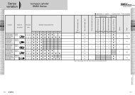
Series variation<br />
Refrigerating<br />
type dryer<br />
Gas type Gas type<br />
Gas type<br />
Air type<br />
Applicable fluids / <strong>flow</strong> control ranges<br />
Model no.<br />
<strong>FCM</strong>-9500 AI<br />
<strong>FCM</strong>-0001 AI<br />
<strong>FCM</strong>-0002 AI<br />
<strong>FCM</strong>-0005 AI<br />
<strong>FCM</strong>-0010 AI<br />
<strong>FCM</strong>-0020 AI<br />
<strong>FCM</strong>-0050 AI<br />
<strong>FCM</strong>-0100AI (only resin)<br />
<strong>FCM</strong>-9500 AR<br />
<strong>FCM</strong>-0001 AR<br />
<strong>FCM</strong>-0002 AR<br />
<strong>FCM</strong>-0005 AR<br />
<strong>FCM</strong>-0010 AR<br />
<strong>FCM</strong>-0020 AR<br />
<strong>FCM</strong>-0050 AR<br />
<strong>FCM</strong>-9500 O2/LN/C1/C3<br />
<strong>FCM</strong>-0001 O2/LN/C1/C3<br />
<strong>FCM</strong>-0002 O2/LN/C1/C3<br />
<strong>FCM</strong>-0005 O2/LN/C1/C3<br />
<strong>FCM</strong>-0010 O2/LN/C1/C3<br />
<strong>FCM</strong>-0002 H2/HE<br />
<strong>FCM</strong>-0005 H2/HE<br />
<strong>FCM</strong>-0010 H2/HE<br />
<strong>FCM</strong>-0020 H2/HE<br />
Applicable<br />
fluids<br />
AIR<br />
Air<br />
N2<br />
Nitrogen<br />
Ar<br />
Argon<br />
O2<br />
Oxygen<br />
13A<br />
City gas<br />
CH4<br />
Methane<br />
C3H8<br />
Propane<br />
H2<br />
Hydrogen<br />
He<br />
Helium<br />
Flow control range (<br />
/min.)<br />
0.01 0.1 1 10 100<br />
0.015 to 0.5<br />
0.03 to 1<br />
0.06 to 2<br />
0.15 to 5<br />
0.3 to 10<br />
0.6 to 20<br />
1.5 to 50<br />
3 to 100<br />
0.015 to 0.5<br />
0.03 to 1<br />
0.06 to 2<br />
0.15 to 5<br />
0.3 to 10<br />
0.6 to 20<br />
1.5 to 50<br />
0.015 to 0.5<br />
0.03 to 1<br />
0.06 to 2<br />
0.15 to 5<br />
0.3 to 10<br />
0.06 to 2<br />
0.15 to 5<br />
0.3 to 10<br />
0.6 to 20<br />
Body material<br />
Resin<br />
SUS<br />
SUS<br />
SUS<br />
SUS<br />
Port <strong>size</strong><br />
Resin<br />
6 push-in<br />
8 push-in<br />
SUS<br />
Rc1/4<br />
9/16-18 UNF<br />
Rc1/4<br />
9/16-18 UNF<br />
Rc1/4<br />
9/16-18 UNF<br />
Rc1/4<br />
9/16-18 UNF<br />
1/4 inch<br />
Double barbed joint<br />
1/4 inch<br />
JXR male joint<br />
Desiccant<br />
type dryer<br />
High polymer<br />
membrane<br />
dryer<br />
Air filter<br />
Auto. drain<br />
/ others<br />
F.R.L.<br />
(Module unit)<br />
F.R.L.<br />
(Separate)<br />
Compact<br />
F.R.<br />
Precise<br />
regulator<br />
F.R.L.<br />
(Related<br />
products)<br />
Clean<br />
F.R.<br />
Electro<br />
pneumatic<br />
regulator<br />
Air<br />
booster<br />
Speed<br />
control valve<br />
Silencer<br />
Check valve<br />
/ others<br />
Joint<br />
/ tube<br />
Vacuum<br />
filter<br />
Vacuum<br />
regulator<br />
Suction<br />
plate<br />
Magnetic<br />
spring buffer<br />
Mechanical<br />
pressure SW<br />
Electronic<br />
pressure SW<br />
Contact / close<br />
contact conf.<br />
SW<br />
I/O specifications<br />
Input<br />
Input signal: specifications<br />
bit<br />
bit<br />
bit<br />
bit<br />
Analog: 0-10V<br />
Preset: 4 points (2 bit) (Note)<br />
Analog: 0-5V<br />
Preset: 4 points (2 bit) (Note)<br />
Analog: 4-20mA<br />
Preset: 4 points (2 bit) (Note)<br />
Parallel: 10bit<br />
Model no.<br />
<strong>FCM</strong>-*-*0AN<br />
<strong>FCM</strong>-*-*0AP<br />
<strong>FCM</strong>-*-*0SN<br />
<strong>FCM</strong>-*-*0SP<br />
<strong>FCM</strong>-*-*1AN<br />
<strong>FCM</strong>-*-*1AP<br />
<strong>FCM</strong>-*-*1SN<br />
<strong>FCM</strong>-*-*1SP<br />
<strong>FCM</strong>-*-*2AN<br />
<strong>FCM</strong>-*-*2AP<br />
<strong>FCM</strong>-*-*2SN<br />
<strong>FCM</strong>-*-*2SP<br />
<strong>FCM</strong>-*-*PAN<br />
<strong>FCM</strong>-*-*PAP<br />
<strong>FCM</strong>-*-*PSN<br />
<strong>FCM</strong>-*-*PSP<br />
Output method<br />
(Note) Preset 8-point (3-bit) input is used customized. (The external integration reset signal input cannot be used.) Contact your <strong>CKD</strong> Sales Office for details.<br />
NPN<br />
PNP<br />
NPN<br />
PNP<br />
NPN<br />
PNP<br />
NPN<br />
PNP<br />
Output<br />
Specifications<br />
Analog 1-5V<br />
Switch<br />
Analog<br />
Switch<br />
Analog<br />
Switch<br />
Analog<br />
Switch<br />
NPN<br />
PNP<br />
1-5V<br />
NPN<br />
PNP<br />
1-5V<br />
NPN<br />
PNP<br />
1-5V<br />
NPN<br />
PNP<br />
Error output<br />
NPN<br />
PNP<br />
NPN<br />
PNP<br />
NPN<br />
PNP<br />
NPN<br />
PNP<br />
NPN<br />
PNP<br />
NPN<br />
PNP<br />
NPN<br />
PNP<br />
NPN<br />
PNP<br />
Air sensor<br />
Pressure SW<br />
for coolant<br />
Small<br />
<strong>flow</strong> sensor<br />
Small<br />
<strong>flow</strong> <strong>controller</strong><br />
Flow sensor<br />
for air<br />
Flow sensor<br />
for water<br />
Total air<br />
system<br />
Total air<br />
system<br />
(Gamma)<br />
Ending<br />
Small <strong>size</strong> <strong>flow</strong> <strong>controller</strong><br />
1335
Refrigerating<br />
type dryer<br />
Desiccant<br />
type dryer<br />
High polymer<br />
membrane<br />
dryer<br />
Air filter<br />
Auto. drain<br />
/ others<br />
F.R.L.<br />
(Module unit)<br />
F.R.L.<br />
(Separate)<br />
Compact<br />
F.R.<br />
Precise<br />
regulator<br />
F.R.L.<br />
(Related<br />
products)<br />
Clean<br />
F.R.<br />
Electro<br />
pneumatic<br />
regulator<br />
Air<br />
booster<br />
Speed<br />
control valve<br />
Silencer<br />
Check valve<br />
/ others<br />
Joint<br />
/ tube<br />
Vacuum<br />
filter<br />
Vacuum<br />
regulator<br />
Suction<br />
plate<br />
Magnetic<br />
spring buffer<br />
Mechanical<br />
pressure SW<br />
Electronic<br />
pressure SW<br />
Contact / close<br />
contact conf.<br />
SW<br />
Air sensor<br />
Pressure SW<br />
for coolant<br />
Small<br />
<strong>flow</strong> sensor<br />
Small<br />
<strong>flow</strong> <strong>controller</strong><br />
Flow sensor<br />
for air<br />
Flow sensor<br />
for water<br />
Total air<br />
system<br />
Total air<br />
system<br />
(Gamma)<br />
Ending<br />
Flow <strong>controller</strong><br />
Safety precautions<br />
Always read this section before starting use.<br />
Refer to Intro 67 for general precautions.<br />
Small <strong>size</strong> <strong>flow</strong> <strong>controller</strong> <strong>FCM</strong> Series<br />
1. Working fluid<br />
DANGER<br />
Do not feed gas at the explosion limit. There is a risk<br />
of explosion.<br />
Before using hydrogen, be sure to purge piping with<br />
inert gas such as nitrogen or argon. Otherwise explosions<br />
could occur.<br />
Do not feed oxygen gas to wetted sections that are<br />
not oil-treated. There is a risk of fire. Even if the product<br />
has oil treatment, if gas other than oxygen gas<br />
has passed even once, do not use the product for<br />
oxygen gas.<br />
WARNING<br />
This product cannot be used as a business meter.<br />
This product does not comply with Measurement<br />
Laws, and cannot be used for commercial business.<br />
This product is for use with gases indicated on the<br />
model. Use of noncompatible fluids lowers product<br />
accuracy and controllability. If hydrogen or helium gas<br />
is passed to a <strong>series</strong> not designated for these, the<br />
sensor safety circuit may prevent operation. (If the<br />
safety circuit operates, the <strong>flow</strong> cannot be measured<br />
or controlled until power is turned off.)<br />
When mixing hydrogen or helium with another gas,<br />
be sure to note reverse gas <strong>flow</strong>. If hydrogen or helium<br />
is passed to a <strong>series</strong> not designated for these,<br />
the sensor safety circuit may prevent operation. (If<br />
the safety circuit operates, the <strong>flow</strong> cannot be measured<br />
or controlled until power is turned off.) When<br />
shutting off gas, provide shutoff valves and shut off<br />
each gas separately as shown below to prevent gas<br />
from <strong>flow</strong>ing in reverse.<br />
Design & Selection<br />
Prevent entry of foreign matter into this product.<br />
If foreign matter gets into this product (dirt, water, or<br />
oil mist into pipes), accuracy and controllability could<br />
drop or the product could fail.<br />
If foreign matter could enter the product, install a filter,<br />
dryer, or oil mist filter upstream from the product.<br />
The mesh provided in this product is used to rectify the <strong>flow</strong><br />
in pipes. It is not a filter for removing foreign matter.<br />
Compressed air from the compressor contains drainage (water,<br />
oxidized oil, foreign matter, etc.), so install a filter, air<br />
dryer, and oil mist filter (microalescer) upstream from the<br />
product.<br />
<br />
Pneumatics<br />
pressure<br />
source<br />
Air dryer<br />
Filter<br />
Regulator<br />
Oil mist filter<br />
<strong>FCM</strong> Series<br />
When using a valve on the primary side of this product, only<br />
use an oil-prohibit specification valve. This <strong>controller</strong> could<br />
malfunction or fail if subject to splattering grease or oil, etc.<br />
When using this <strong>controller</strong> for liquefied gas such as<br />
propane gas, evaporate the gas. This <strong>controller</strong> could<br />
fail if liquefied gas is fed.<br />
When using this product to control burner air-fuel ratio,<br />
take measures in the design stages to prevent<br />
backfire, and to prevent adverse effect to this product<br />
even if a backfire should occur. A rise in the pipe's<br />
internal pressure and flame caused by a burner's<br />
backfire could damage this product.<br />
Gas supply<br />
source<br />
<strong>FCM</strong> Series<br />
(Hydrogen/helium)<br />
Shut off<br />
valve<br />
Gas supply<br />
source<br />
<strong>FCM</strong> Series<br />
(Other than hydrogen/helium)<br />
Shut off<br />
valve<br />
1336
<strong>FCM</strong> Series<br />
2. Working environment<br />
WARNING<br />
Corrosive environment<br />
Do not use this product in an environment containing<br />
corrosive gases such as sulfurous acid.<br />
Ambient temperature, fluid temperature<br />
Keep the ambient temperature and fluid temperature<br />
within 0 to 50°C.<br />
Even if the temperature is within the specified range,<br />
do not use this product if the ambient temperature<br />
and fluid temperature could suddenly change and<br />
cause dew to condense.<br />
Guaranteed withstanding pressure and operating<br />
pressure difference range<br />
Using this product at a level exceeding the guaranteed<br />
withstanding pressure and operating pressure difference<br />
could cause damage. Follow the specified range.<br />
Drip-proof environment<br />
This product's protective structure is IP40 or equivalent.<br />
Do not install it where it could be subject to water,<br />
salt, dust, or cutting chips, or a compressed or<br />
decompressed environment. This product cannot be<br />
used where the temperature changes sharply or in a<br />
highly humid environment as dew condensation in<br />
the product could cause damage.<br />
This product's solenoid proportional valve does not<br />
have a complete close-stop.<br />
If a complete close-stop is required, provide a separate<br />
external shutoff valve.<br />
When the external shutoff valve is closed, wait with<br />
this product's valve fully closed (set <strong>flow</strong> rate: zero). If<br />
this product is left in normal control while this external<br />
shutoff valve is closed, an instant over<strong>flow</strong> could<br />
occur when the external shutoff valve is opened.<br />
When using for applications that turn ON/OFF at a high<br />
frequency, the life of the proportional valve may be shortened<br />
depending on use. Contact <strong>CKD</strong> when using for<br />
applications that turn ON/OFF at a high frequency.<br />
Do not install this product at a place that moves or<br />
vibrates. Vibration or impact could cause this <strong>controller</strong><br />
to malfunction.<br />
CAUTION<br />
Check the leakage current to prevent malfunction<br />
caused by current leaking from other <strong>controller</strong>s.<br />
When using a programmable <strong>controller</strong>, etc., the leakage<br />
current could cause this product to malfunction.<br />
Design & Selection<br />
Due to wiring, the current input power ground and<br />
signal common are the same.<br />
When driving several of these products with one PLC<br />
and D/A unit, depending on the D/A unit's circuit, the<br />
correct signal may not be input because of wiring problems.<br />
Consult with the PLC maker before using.<br />
Current input is used with input signal 1-5 V, but unlike<br />
other voltage input, the input impedance is <strong>small</strong><br />
at 250 , so a signal generator that matches this impedance<br />
must be used.<br />
Monitor the pipe's pressure loss<br />
When piping this product, check that the differential<br />
pressure between the upstream side and downstream<br />
side is within the operating pressure difference range<br />
(refer to pages 1343, 1345). Controller may not operate<br />
properly if used outside of the operating pressure<br />
difference range. Operation may not be as expected<br />
if there is an orifice or restriction on the secondary<br />
side (downstream) of the product. Care must be taken.<br />
3. Flow unit<br />
CAUTION<br />
This <strong>controller</strong>'s <strong>flow</strong> rate is measured with mass <strong>flow</strong><br />
not affected by pressure. The unit is /min., that is the<br />
mass <strong>flow</strong> converted to volumetric <strong>flow</strong> at 20°C 1 barometric<br />
pressure (101 kPa).<br />
Refrigerating<br />
type dryer<br />
Desiccant<br />
type dryer<br />
High polymer<br />
membrane<br />
dryer<br />
Air filter<br />
Auto. drain<br />
/ others<br />
F.R.L.<br />
(Module unit)<br />
F.R.L.<br />
(Separate)<br />
Compact<br />
F.R.<br />
Precise<br />
regulator<br />
F.R.L.<br />
(Related<br />
products)<br />
Clean<br />
F.R.<br />
Electro<br />
pneumatic<br />
regulator<br />
Air<br />
booster<br />
Speed<br />
control valve<br />
Silencer<br />
Check valve<br />
/ others<br />
Joint<br />
/ tube<br />
Vacuum<br />
filter<br />
Vacuum<br />
regulator<br />
Suction<br />
plate<br />
Magnetic<br />
spring buffer<br />
Mechanical<br />
pressure SW<br />
Electronic<br />
pressure SW<br />
Contact / close<br />
contact conf.<br />
SW<br />
Air sensor<br />
Pressure SW<br />
for coolant<br />
Small<br />
<strong>flow</strong> sensor<br />
Small<br />
<strong>flow</strong> <strong>controller</strong><br />
Flow sensor<br />
for air<br />
Flow sensor<br />
for water<br />
Total air<br />
system<br />
Total air<br />
system<br />
(Gamma)<br />
Ending<br />
Small <strong>size</strong> <strong>flow</strong> <strong>controller</strong><br />
1337
<strong>FCM</strong> Series<br />
Refrigerating<br />
type dryer<br />
Desiccant<br />
type dryer<br />
High polymer<br />
membrane<br />
dryer<br />
Air filter<br />
Auto. drain<br />
/ others<br />
F.R.L.<br />
(Module unit)<br />
F.R.L.<br />
(Separate)<br />
Compact<br />
F.R.<br />
Precise<br />
regulator<br />
F.R.L.<br />
(Related<br />
products)<br />
Clean<br />
F.R.<br />
Electro<br />
pneumatic<br />
regulator<br />
Air<br />
booster<br />
Speed<br />
control valve<br />
Silencer<br />
Check valve<br />
/ others<br />
Joint<br />
/ tube<br />
Vacuum<br />
filter<br />
Vacuum<br />
regulator<br />
Suction<br />
plate<br />
Magnetic<br />
spring buffer<br />
Mechanical<br />
pressure SW<br />
Electronic<br />
pressure SW<br />
Contact / close<br />
contact conf.<br />
SW<br />
Air sensor<br />
Pressure SW<br />
for coolant<br />
Small<br />
<strong>flow</strong> sensor<br />
Small<br />
<strong>flow</strong> <strong>controller</strong><br />
Flow sensor<br />
for air<br />
Flow sensor<br />
for water<br />
Total air<br />
system<br />
Total air<br />
system<br />
(Gamma)<br />
Ending<br />
1. Wiring<br />
DANGER<br />
Use power voltage and output within the specified voltage.<br />
If voltage exceeding the specified voltage is applied,<br />
the sensor could malfunction or be damaged, or electrical<br />
shock or fire could occur. Do not use a load<br />
exceeding the output rating. Failure to observe this<br />
could result in output damage or fire.<br />
WARNING<br />
Check the connector pin and cable core wire color<br />
when wiring. Incorrect connections could result in<br />
sensor damage, problems, and malfunctions, so<br />
check the wire color against the instruction manual<br />
before wiring.<br />
Check wiring insulation.<br />
Check that wires do not contact other circuits, that<br />
there is no ground fault, and that the insulator between<br />
terminals is not defective. An overload could<br />
<strong>flow</strong> to the product, and result in damage.<br />
Use a DC stabilized power supply, within the specified<br />
rating, insulated from the AC power supply. Failure<br />
to insulate the power supply could result in electric<br />
shock. If power is not stabilized, the peak could<br />
be exceeded during the summer. This could damage<br />
this product or cause accuracy to drop.<br />
Stop <strong>controller</strong> and devices, and turn power OFF before<br />
wiring. Starting operation suddenly could result<br />
in unpredictable operation and hazards. Conduct an<br />
energized test with <strong>controller</strong>s and devices stopped,<br />
and set target switch data. Discharge any static electricity<br />
accumulated by personnel or tools before and<br />
during work. Connect and wire bending resistant<br />
material, such as robot wire material, for movable<br />
sections.<br />
Do not use this <strong>controller</strong> at levels exceeding the<br />
power voltage range. If voltage exceeding the specified<br />
range is applied, or if an AC power (100 VAC) is<br />
applied, the <strong>controller</strong> could break or burn.<br />
Installation & Adjustment<br />
Do not short-circuit the load. This product could break<br />
or burn.<br />
Use stabilized DC power completely separated from<br />
the AC primary side for stainless steel construction.<br />
Connect either the plus or minus side of the power<br />
supply to the FG. A varistor (limit voltage. 40 V) is<br />
connected between the stainless steel internal power<br />
circuit and stainless steel device to prevent dielectric<br />
breakdown of the sensor. Do not conduct a withstand<br />
voltage test or insulation resistance test between the<br />
internal power circuit and stainless steel device. Disconnect<br />
wiring if this testing is required. An excessive<br />
potential difference between the power and stainless<br />
steel device will cause the internal parts to burn.<br />
After installing, connecting, and wiring the stainless<br />
steel device, electrical welding of the device or frame<br />
or short-circuit accidents, etc., could cause the welding<br />
current, the excessive high voltage caused by<br />
welding, or a surge voltage, etc., to run through wiring<br />
or ground wire connected between the above<br />
devices. This could result in damage to wires or devices.<br />
Conduct any work such as electrical welding<br />
after removing this device and disconnecting all electric<br />
wires connected to the FG.<br />
CAUTION<br />
The option shield cable connector is a shielded wire.<br />
Insulate wires that are not being used so that they do<br />
not contact other wires, including shielded wires. If<br />
inadvertently connected to the ground, etc., the <strong>controller</strong><br />
could malfunction or break.<br />
Check the direction and fit the D-sub connector into<br />
the back.<br />
Lock the D-sub connector so that it does not dislocate.<br />
Before loosening the lock, fix the fixing block<br />
with a tool, etc.<br />
Separate this product and its wiring as far away from<br />
sources of noise such as power distribution wires. Provide<br />
separate measures for surge applied to the power<br />
cable.<br />
1338
<strong>FCM</strong> Series<br />
2. Piping<br />
CAUTION<br />
Pipe based on the fluid direction and the direction<br />
indicated on the device.<br />
Tightening the 4S or 4RM port <strong>size</strong> (hydrogen, helium<br />
model) joint<br />
Tightening the joint<br />
4RM (1/4 inch JXR male joint) ··· When gasket material is<br />
nickel or SUS316<br />
Tighten the nut by hand until the gasket contacts the bead,<br />
then tighten 1/8 of a turn using a tool.<br />
Nut<br />
4S (double-barbed joint) ··· Confirm that the front ferrule,<br />
back ferrule, and nut are correctly attached, and insert<br />
tubing until it contacts the back of the main body. Tighten<br />
the nut by hand as far as possible, then tighten 1 1/4 of a<br />
turn using a tool.<br />
Before piping, clean pipes with compressed air to<br />
remove any foreign matter of cutting chips, etc. The<br />
rectifying unit or platinum sensor could be damaged<br />
if foreign matter or cutting chips get in.<br />
When attaching piping to this product, use the following<br />
torques as reference so that excessive screwing torque<br />
or load torque is not applied to the connection port.<br />
Port thread<br />
Rc1/4<br />
9/16-18UNF<br />
Gasket<br />
Front ferrule<br />
Holder<br />
Back ferrule<br />
6 to 8<br />
6 to 8<br />
Bead<br />
Nut<br />
Tightening torque N·m<br />
Tube<br />
When piping, put a wrench, etc., on the stainless steel<br />
device so that force is not applied to the resin section.<br />
Check that sealing tape or adhesive does not get<br />
inside when piping.<br />
When winding fluorine resin sealing tape around<br />
threads, wind the sealing tape one to two times, leaving<br />
two to three threads open at the end of the screw.<br />
Press down on the tape to stick it onto threads. When<br />
using liquid sealing agent, leave one to two threads<br />
open from the end, and avoid applying too much.<br />
Check that the sealing agent does not get on the<br />
device's threads.<br />
(Good)<br />
Seal tape<br />
Solid/liquid sealant<br />
Solid<br />
liquid<br />
sealant<br />
Solid<br />
liquid<br />
sealant<br />
(Not good) (Good) (Not good)<br />
Sealant may stick to threads when piping is removed.<br />
Be sure to remove sealant before repiping.<br />
Connect a joint even when using the stainless steel<br />
device with the OUT side opened. The port filter could<br />
come off.<br />
When using resin construction, do not bend the tube<br />
near the push-in joint. If strain could be applied to the<br />
tube near the push-in joint, attach an insert ring onto<br />
the tube and insert into the push-in joint.<br />
When using resin construction, accurately insert the<br />
tube and confirm that it does not dislocate even when<br />
pulled. Cut the tube at a right angle with a dedicated<br />
cutter before using.<br />
After piping, confirm that no gas is leaking.<br />
When using this product for oxygen gas, monitor the<br />
following points.<br />
Piping work must be completed by personnel with expertise on<br />
handling oxygen gas.<br />
Use oil-treated pipes.<br />
Remove any dirt or burrs from piping before attaching to this<br />
product.<br />
Attach a filter to the primary side of this product.<br />
Refrigerating<br />
type dryer<br />
Desiccant<br />
type dryer<br />
High polymer<br />
membrane<br />
dryer<br />
Air filter<br />
Auto. drain<br />
/ others<br />
F.R.L.<br />
(Module unit)<br />
F.R.L.<br />
(Separate)<br />
Compact<br />
F.R.<br />
Precise<br />
regulator<br />
F.R.L.<br />
(Related<br />
products)<br />
Clean<br />
F.R.<br />
Electro<br />
pneumatic<br />
regulator<br />
Air<br />
booster<br />
Speed<br />
control valve<br />
Silencer<br />
Check valve<br />
/ others<br />
Joint<br />
/ tube<br />
Vacuum<br />
filter<br />
Vacuum<br />
regulator<br />
Suction<br />
plate<br />
Magnetic<br />
spring buffer<br />
Mechanical<br />
pressure SW<br />
Electronic<br />
pressure SW<br />
Contact / close<br />
contact conf.<br />
SW<br />
Air sensor<br />
Pressure SW<br />
for coolant<br />
Small<br />
<strong>flow</strong> sensor<br />
Small<br />
<strong>flow</strong> <strong>controller</strong><br />
Flow sensor<br />
for air<br />
Flow sensor<br />
for water<br />
Total air<br />
system<br />
Total air<br />
system<br />
(Gamma)<br />
Ending<br />
Small <strong>size</strong> <strong>flow</strong> <strong>controller</strong><br />
1339
<strong>FCM</strong> Series<br />
Refrigerating<br />
type dryer<br />
Desiccant<br />
type dryer<br />
High polymer<br />
membrane<br />
dryer<br />
Air filter<br />
Auto. drain<br />
/ others<br />
F.R.L.<br />
(Module unit)<br />
F.R.L.<br />
(Separate)<br />
Compact<br />
F.R.<br />
Precise<br />
regulator<br />
F.R.L.<br />
(Related<br />
products)<br />
Clean<br />
F.R.<br />
Electro<br />
pneumatic<br />
regulator<br />
Air<br />
booster<br />
Speed<br />
control valve<br />
Silencer<br />
Check valve<br />
/ others<br />
Joint<br />
/ tube<br />
Vacuum<br />
filter<br />
Vacuum<br />
regulator<br />
Suction<br />
plate<br />
Magnetic<br />
spring buffer<br />
Mechanical<br />
pressure SW<br />
Electronic<br />
pressure SW<br />
Contact / close<br />
contact conf.<br />
SW<br />
Air sensor<br />
Pressure SW<br />
for coolant<br />
Small<br />
<strong>flow</strong> sensor<br />
Small<br />
<strong>flow</strong> <strong>controller</strong><br />
Flow sensor<br />
for air<br />
Flow sensor<br />
for water<br />
Total air<br />
system<br />
Total air<br />
system<br />
(Gamma)<br />
Ending<br />
CAUTION<br />
Output accuracy is affected by the temperature characteristics<br />
and heat self-generated when energized.<br />
Provide a standby time (10 minutes or more after turning<br />
power ON) when using.<br />
If a failure occurs during operation, turn power OFF<br />
immediately and stop use. Contact your dealer.<br />
This product does not control the <strong>flow</strong> for two seconds<br />
after power is turned ON so it completes self-diagnosis.<br />
Provide a control circuit and program that ignore<br />
signals for two seconds after power is turned ON.<br />
Keep this product's <strong>flow</strong> within the rated <strong>flow</strong> range.<br />
Use this product within the operating differential pressure<br />
range.<br />
When the setting is changed, control devices could<br />
operate unintentionally. Stop devices before changing<br />
settings.<br />
Regularly inspect the product at least once a year<br />
and confirm that it is operating correctly.<br />
Do not disassemble or modify this product. Doing so<br />
could result in faults.<br />
This case is made of resin. Do not use solvent, alcohol<br />
or any other cleaning agent to remove contamination,<br />
etc., or the resin case could be corroded or<br />
damaged. Wipe off any dirt with a rag soaked in a<br />
diluted neutral detergent solution and wrung out well.<br />
Monitor leading of the surge current<br />
When <strong>controller</strong> power is shared with an inductive<br />
load that generates a surge, such as a solenoid valve<br />
or relay, if the circuit is cut off while the inductive load<br />
is functioning, the surge current could enter the output<br />
circuit and cause damage depending on where<br />
the surge absorption element is installed.<br />
During Use & Maintenance<br />
Take the following types of measures to prevent damage<br />
from surge current led in.<br />
(1) Separate the power supply for output comprising<br />
the inductive load, such as the solenoid valve and<br />
relay, and input, such as the <strong>flow</strong> <strong>controller</strong>.<br />
(2) If separate power supplies cannot be used, directly<br />
install a surge absorption element for all inductive<br />
loads. Note that the surge absorption element<br />
connected to the PLC, etc., protects only<br />
that device.<br />
(3) Connect a surge absorption element to the following<br />
on power wiring as shown below as a measure<br />
against disconnections in unspecific areas.<br />
Input<br />
components<br />
Input<br />
components<br />
Input<br />
components<br />
When devices are connected to a connector, the output<br />
circuit could be damaged by the above if the connector<br />
is disconnected while power is ON. Turn power<br />
OFF before connecting or disconnecting the connector.<br />
Surge absorbing element<br />
(To be installed later)<br />
Circuit cutoff with disconnection<br />
or emergency stop<br />
Surge absorbing element<br />
(Integrated)<br />
Flow <strong>controller</strong><br />
Relay<br />
Solenoid valve<br />
Main circuit<br />
ON<br />
Surge current<br />
PLC<br />
PLC output<br />
1340
Refrigerating<br />
type dryer<br />
Desiccant<br />
type dryer<br />
High polymer<br />
membrane<br />
dryer<br />
Air filter<br />
Auto. drain<br />
/ others<br />
F.R.L.<br />
(Module unit)<br />
F.R.L.<br />
(Separate)<br />
Compact<br />
F.R.<br />
Precise<br />
regulator<br />
F.R.L.<br />
(Related<br />
products)<br />
Clean<br />
F.R.<br />
Electro<br />
pneumatic<br />
regulator<br />
Air<br />
booster<br />
Speed<br />
control valve<br />
Silencer<br />
Check valve<br />
/ others<br />
Joint<br />
/ tube<br />
Vacuum<br />
filter<br />
Vacuum<br />
regulator<br />
Suction<br />
plate<br />
Magnetic<br />
spring buffer<br />
Mechanical<br />
pressure SW<br />
Electronic<br />
pressure SW<br />
Contact / close<br />
contact conf.<br />
SW<br />
Air sensor<br />
Pressure SW<br />
for coolant<br />
Small<br />
<strong>flow</strong> sensor<br />
Small<br />
<strong>flow</strong> <strong>controller</strong><br />
Flow sensor<br />
for air<br />
Flow sensor<br />
for water<br />
Total air<br />
system<br />
Total air<br />
system<br />
(Gamma)<br />
Ending<br />
Standard model<br />
Low pressure differential model<br />
(Only stainless steel)<br />
Control range<br />
Responsiveness * 1<br />
9500 to 0020, L9500 to L0010<br />
0050 to 0100<br />
Control Precision<br />
Repeatability<br />
Temperature characteristics<br />
Pressure characteristics<br />
Standard differential pressure Note 4<br />
Operating differential pressure range Note 5<br />
Pressure<br />
H6/H8 (resin body)<br />
Withstanding pressure * 3<br />
8A/UF (SUS body)<br />
Ambient temperature / humidity<br />
0<br />
Input signal/ 1<br />
* 4<br />
pre-set input 2<br />
P<br />
AN<br />
I/O<br />
Output signal * 5<br />
AP<br />
SN<br />
SP<br />
Flow<br />
display<br />
Display method<br />
Display range, display resolution<br />
Function of integration<br />
Power<br />
supply<br />
Power voltage<br />
Current consumption<br />
Installation attitude<br />
Wet area material<br />
Weight<br />
* 3<br />
* 3<br />
H6/H8 (resin body)<br />
8A/UF (SUS body)<br />
H6/H8 (resin body)<br />
8A/UF (SUS body)<br />
Protective structure<br />
Protective circuit Note 6<br />
EMC directive<br />
Small <strong>size</strong> <strong>flow</strong> <strong>controller</strong><br />
<strong>FCM</strong> Series<br />
Air, nitrogen, argon, oxygen, city gas, methane, propane (<strong>flow</strong> rate range: 0.5 to 100 /min.)<br />
Hydrogen, helium (<strong>flow</strong> rate range: 0 to 20 /min.)<br />
<strong>FCM</strong> Series for air, nitrogen, argon, oxygen, city gas, methane, propane<br />
Specifications<br />
Descriptions <strong>FCM</strong>- (*1) (*2) - (*3) (*4) (*5)<br />
Valve drive method<br />
Proportional solenoid valve When not energized: Closed<br />
Flow range<br />
AI (air, nitrogen) AR (argon) O2 (oxygen) LN (city gas) C1 (methane) C3 (propane)<br />
9500 0 to 500m /min.<br />
0001 0 to 1 /min.<br />
0002 0 to 2 /min.<br />
0005 0 to 5 /min.<br />
0010 0 to 10 /min.<br />
0020 0 to 20 /min.<br />
Full scale <strong>flow</strong><br />
* 1 0050 0 to 50 /min.<br />
Note 1<br />
0100 0 to 100 /min. (only resin)<br />
L9500 0 to 500m /min.<br />
L0001 0 to 1 /min.<br />
L0002 0 to 2 /min.<br />
L0005 0 to 5 /min.<br />
L0010 0 to 10 /min.<br />
AI Compressed air, nitrogen<br />
AR Argon<br />
Applicable fluids<br />
O2 Oxygen (oil-prohibited specifications)<br />
* 2<br />
Note 2<br />
LN City gas (13A) Note 3<br />
C1 Methane (CH4 100%)<br />
C3 Propane (C3H8 100%)<br />
H6 6 push-in, resin (excluding 50, 100 /min)<br />
Port <strong>size</strong>/<br />
H8 8 push-in, resin<br />
* 3<br />
Body material<br />
8A Rc1/4, stainless steel<br />
UF 9/16-18UNF, stainless steel<br />
3 to 100%F.S.<br />
Within 0.5sec. at setting 5%F.S. (TYP)<br />
Within 1sec. at setting 5%F.S. (TYP)<br />
3%F.S. or less<br />
1%F.S. or less<br />
0.1%F.S./ or less (25 reference)<br />
1%F.S. or less per 98kPa (standard differential pressure reference)<br />
Refer to the separate table<br />
Refer to the separate table<br />
490kPa<br />
980kPa<br />
0 to 50 , 90%RH or less (no dew)<br />
0 to 10 VDC (6.7 ) / 4 points (2 bit)<br />
0 to 5 VDC (10 ) / 4 points (2 bit)<br />
4 to 20 VDC (250 ) / 4 points (2 bit)<br />
Parallel 10bit / None<br />
Analog output: 1-5V (connected load impedance 500k and over)<br />
Error output: NPN open collector output, 50mA or less, voltage drop 2.4V or less<br />
Analog output: 1-5V (connected load impedance 500k and over)<br />
Error output: PNP open collector output, 50mA or less, voltage drop 2.4V or less<br />
Switch output: NPN open collector output, 50mA or less, voltage drop 2.4V or less<br />
Error output: NPN open collector output, 50mA or less, voltage drop 2.4V or less<br />
Switch output: PNP open collector output, 50mA or less, voltage drop 2.4V or less<br />
Error output: PNP open collector output, 50mA or less, voltage drop 2.4V or less<br />
3-digit 7-segment LED, Display precision: control precision 1 digit<br />
Refer to the separate table<br />
Refer to the separate table<br />
24 VDC 10% (safety power supply with ripple ratio 2% or less)<br />
250mA or less<br />
Free<br />
Polyamide resin, fluoro rubber, stainless steel, alumina, silicone, solder<br />
Stainless steel, fluoro rubber, alumina, silicone, solder<br />
Approx. 200g<br />
Approx. 480g<br />
IEC standards IP40<br />
Power supply reverse connection prevention, switch output reverse connection prevention, switch output load short-circuit protection<br />
EN55011, EN61000-6-2, EN61000-4-2/3/4/6/8<br />
1342
Pressure<br />
Standard differential pressure / operating differential pressure Note 4, 5<br />
(Standard model)<br />
Applicable fluids *2<br />
AI<br />
AR<br />
O2<br />
LN/C1<br />
C3<br />
Standard differential<br />
pressure (kPa)<br />
Operating differential<br />
pressure (kPa)<br />
Standard differential<br />
pressure (kPa)<br />
Operating differential<br />
pressure (kPa)<br />
Standard differential<br />
pressure (kPa)<br />
Operating differential<br />
pressure (kPa)<br />
Standard differential<br />
pressure (kPa)<br />
Operating differential<br />
pressure (kPa)<br />
Standard differential<br />
pressure (kPa)<br />
Operating differential<br />
pressure (kPa)<br />
(Low pressure differential model)<br />
Applicable fluids *2<br />
AI/O2<br />
LN/C1<br />
C3<br />
Display/integration<br />
Flow display<br />
Function of integration<br />
Standard differential<br />
pressure (kPa)<br />
Operating differential<br />
pressure (kPa)<br />
Display range<br />
Display resolution<br />
Display range<br />
Display resolution<br />
Pulse output rate<br />
Flow rate range *1<br />
9500 0001 0002 0005 0010 0020 0050 0100<br />
50<br />
20 to 150<br />
50<br />
20 to 150<br />
50<br />
20 to 150<br />
50<br />
20 to 150<br />
50<br />
20 to 150<br />
20<br />
5 to 50<br />
100<br />
50 to 200<br />
100<br />
50 to 200<br />
100<br />
50 to 200<br />
50<br />
20 to 150<br />
50<br />
20 to 150<br />
100<br />
50 to 250<br />
100<br />
50 to 250<br />
100<br />
50 to 250<br />
50<br />
20 to 150<br />
50<br />
20 to 150<br />
20<br />
5 to 50<br />
100<br />
50 to 250<br />
100<br />
50 to 250<br />
100<br />
50 to 250<br />
50<br />
20 to 150<br />
50<br />
20 to 150<br />
20<br />
5 to 50<br />
100<br />
50 to 250<br />
100<br />
50 to 250<br />
100<br />
50 to 250<br />
50<br />
30 to 150<br />
50<br />
30 to 150<br />
150<br />
100 to 300<br />
150<br />
100 to 300<br />
20<br />
5 to 50<br />
200<br />
150 to 300<br />
200<br />
150 to 300<br />
Flow rate range *1<br />
L9500 L0001 L0002 L0005 L0010<br />
300<br />
250 to 350<br />
20<br />
10 to 50<br />
Note 1: Converted to volumetric <strong>flow</strong> at 20 1 barometric pressure (101kPa)<br />
Note 2: When using compressed air, use clean air that complies to JIS B 8392-1:2003 Class 1.1.1 to 1.6.2. Compressed air from the compressor<br />
contains drainage (water, oxidized oil, foreign matter, etc.). Install a filter (filtration: 5 m), air dryer (minimum pressure dew point: 10<br />
or less), and oil mist filter (maximum oil concentration: 0.1 mg/m 3 ) on the primary side of this product to maintain product functions.<br />
<br />
Pneumatics<br />
pressure source<br />
Air dryer<br />
Filter<br />
<br />
Air filter: F Series<br />
Oil mist filter: M Series<br />
Flow rate range *1<br />
9500 0001 0002 0005 0010<br />
L9500 L0001 L0002 L0005 L0010<br />
0020 0050 0100<br />
0 to 500m /min. 0.00 to 1.00 /min. 0.00 to 2.00 /min. 0.00 to 5.00 /min. 0.0 to 10.0 /min. 0.0 to 20.0 /min. 0.0 to 50.0 /min. 0 to 100 /min.<br />
1m /min 0.01 /min 0.01 /min 0.01 /min 0.1 /min 0.1 /min 0.1 /min 1 /min<br />
999999m 9999.99 9999.99 9999.99 99999.9 99999.9 99999.9 999999<br />
1m 0.01 0.01 0.01 0.1 0.1 0.1 1<br />
5m 0.01 0.02 0.05 0.1 0.2 0.5 1<br />
Regulator<br />
Oil mist filter<br />
(Micro alescer)<br />
<strong>FCM</strong> Series<br />
<strong>FCM</strong> Series<br />
Specifications<br />
Refrigerating<br />
type dryer<br />
Desiccant<br />
type dryer<br />
High polymer<br />
membrane<br />
dryer<br />
Air filter<br />
Auto. drain<br />
/ others<br />
F.R.L.<br />
(Module unit)<br />
F.R.L.<br />
(Separate)<br />
Compact<br />
F.R.<br />
Precise<br />
regulator<br />
F.R.L.<br />
(Related<br />
products)<br />
Clean<br />
F.R.<br />
Electro<br />
pneumatic<br />
regulator<br />
Air<br />
booster<br />
Speed<br />
control valve<br />
Silencer<br />
Check valve<br />
/ others<br />
Joint<br />
/ tube<br />
Vacuum<br />
filter<br />
Vacuum<br />
regulator<br />
Suction<br />
plate<br />
Magnetic<br />
spring buffer<br />
Mechanical<br />
pressure SW<br />
Electronic<br />
pressure SW<br />
Contact / close<br />
contact conf.<br />
SW<br />
Air sensor<br />
Pressure SW<br />
for coolant<br />
Small<br />
<strong>flow</strong> sensor<br />
Small<br />
<strong>flow</strong> <strong>controller</strong><br />
Flow sensor<br />
for air<br />
Flow sensor<br />
for water<br />
Total air<br />
system<br />
Total air<br />
system<br />
(Gamma)<br />
Ending<br />
When using for other than compressed air, use dry gas that does not contain corrosive elements such as chlorine, sulfur, or acids, and<br />
clean gas that does not contain dust or oil mist.<br />
Note 3: City gas 13 A is for methane (CH4) 88% gas generated from LNG.<br />
Note 4: The standard differential pressure is the differential pressure when this product is calibrated.<br />
Note 5: The operating differential pressure is the differential pressure required to operate this product normally. Contact <strong>CKD</strong> when using this product at a level exceeding the operating differential pressure.<br />
Note 6: This product's protective circuit is effective only for specific incorrect connections and load short-circuits. It does not necessarily provide protection for all incorrect connections.<br />
Small <strong>size</strong> <strong>flow</strong> <strong>controller</strong><br />
1343
<strong>FCM</strong> Series<br />
Refrigerating<br />
type dryer<br />
Desiccant<br />
type dryer<br />
High polymer<br />
membrane<br />
dryer<br />
Air filter<br />
Auto. drain<br />
/ others<br />
F.R.L.<br />
(Module unit)<br />
F.R.L.<br />
(Separate)<br />
Compact<br />
F.R.<br />
Precise<br />
regulator<br />
F.R.L.<br />
(Related<br />
products)<br />
Clean<br />
F.R.<br />
Electro<br />
pneumatic<br />
regulator<br />
Air<br />
booster<br />
Speed<br />
control valve<br />
Silencer<br />
Check valve<br />
/ others<br />
Joint<br />
/ tube<br />
Vacuum<br />
filter<br />
Vacuum<br />
regulator<br />
Suction<br />
plate<br />
Magnetic<br />
spring buffer<br />
Mechanical<br />
pressure SW<br />
Electronic<br />
pressure SW<br />
Contact / close<br />
contact conf.<br />
SW<br />
Air sensor<br />
Pressure SW<br />
for coolant<br />
Small<br />
<strong>flow</strong> sensor<br />
Small<br />
<strong>flow</strong> <strong>controller</strong><br />
Flow sensor<br />
for air<br />
Flow sensor<br />
for water<br />
Total air<br />
system<br />
Total air<br />
system<br />
(Gamma)<br />
<strong>FCM</strong> Series for hydrogen, helium<br />
Specifications<br />
Descriptions <strong>FCM</strong>- (*1) (*2) - (*3) (*4) (*5)<br />
Valve drive method<br />
Full scale <strong>flow</strong><br />
Note 1<br />
Applicable fluids<br />
Port <strong>size</strong><br />
* 1<br />
* 2<br />
* 3<br />
0002<br />
0005<br />
0010<br />
0020<br />
H2<br />
HE<br />
8A<br />
UF<br />
4S<br />
4RM<br />
Proportional solenoid valve When not energized: Closed<br />
Flow range<br />
H2 (hydrogen)<br />
HE (helium)<br />
0 to 2 /min.<br />
0 to 5 /min.<br />
0 to 10 /min.<br />
0 to 20 /min.<br />
Hydrogen<br />
Helium<br />
Rc1/4<br />
9/16-18UNF<br />
1/4 inch double barbed joint<br />
1/4 inch JXR male joint<br />
3 to 100%F.S.<br />
Within 0.5sec. at setting 5%F.S. (TYP)<br />
3%F.S. or less<br />
1%F.S. or less<br />
0.2%F.S./ or less (25 reference)<br />
1%F.S. or less per 98kPa (standard differential pressure reference)<br />
Refer to the separate table<br />
Refer to the separate table<br />
980kPa<br />
0 to 50 , 90%RH or less (no dew)<br />
1 x 10 -6 Pa/m 3 /s or less (helium leak rate)<br />
0 to 10 VDC (6.7 ) / 4 points (2 bit)<br />
0 to 5 VDC (10 ) / 4 points (2 bit)<br />
4 to 20 VDC (250 ) / 4 points (2 bit)<br />
Parallel 10bit / None<br />
Control range<br />
Responsiveness<br />
* 1<br />
Control Precision<br />
Repeatability<br />
Temperature characteristics<br />
Pressure characteristics<br />
Standard differential pressure Note 2<br />
Pressure Operating differential pressure range Note 3<br />
Withstanding pressure<br />
Ambient temperature / humidity<br />
External leakage<br />
0<br />
Input signal/ 1<br />
* 4<br />
pre-set input 2<br />
P<br />
I/O<br />
AN<br />
AP<br />
Output signal * 5<br />
SN<br />
SP<br />
Flow<br />
display<br />
Display method<br />
Display range, display resolution<br />
Function of integration<br />
Power<br />
supply<br />
Power voltage<br />
Current consumption<br />
Installation attitude<br />
Wet area material<br />
Weight<br />
* 3<br />
8A/UF<br />
4S/4RM<br />
Protective structure<br />
Protective circuit Note 4<br />
EMC directive<br />
Analog output: 1-5V (connected load impedance 500k and over)<br />
Error output: NPN open collector output, 50mA or less, voltage drop 2.4V or less<br />
Analog output: 1-5V (connected load impedance 500k and over)<br />
Error output: PNP open collector output, 50mA or less, voltage drop 2.4V or less<br />
Switch output: NPN open collector output, 50mA or less, voltage drop 2.4V or less<br />
Error output: PNP open collector output, 50mA or less voltage drop 2.4V or less<br />
Switch output: PNP open collector output, 50mA or less, voltage drop 2.4V or less<br />
Error output: PNP open collector output, 50mA or less, voltage drop 2.4V or less<br />
3-digit 7-segment LED, display system: control precision 1 digit<br />
Refer to the separate table<br />
Refer to the separate table<br />
24 VDC 10% (safety power supply with ripple ratio 1% or less)<br />
270mA or less<br />
Free<br />
Stainless steel, fluoro rubber, alumina, silicone, solder<br />
Approx. 480g<br />
Approx. 560g<br />
IEC standards IP40<br />
Power supply reverse connection prevention, switch output reverse connection prevention, switch output load short-circuit protection<br />
EN55011, EN61000-6-2, EN61000-4-2/3/4/6/8<br />
Ending<br />
1344
Pressure<br />
Standard differential pressure / operating differential pressure<br />
H2<br />
HE<br />
Standard differential<br />
pressure (kPa)<br />
Operating differential<br />
pressure (kPa)<br />
Standard differential<br />
pressure (kPa)<br />
Operating differential<br />
pressure (kPa)<br />
20<br />
10 to 50<br />
50<br />
20 to 100<br />
50<br />
30 to 80<br />
100<br />
50 to 150<br />
50<br />
30 to 80<br />
100<br />
50 to 150<br />
<strong>FCM</strong> Series<br />
Specifications<br />
50<br />
30 to 80<br />
100<br />
50 to 150<br />
Refrigerating<br />
type dryer<br />
Desiccant<br />
type dryer<br />
High polymer<br />
membrane<br />
dryer<br />
Air filter<br />
Auto. drain<br />
/ others<br />
F.R.L.<br />
(Module unit)<br />
F.R.L.<br />
(Separate)<br />
Compact<br />
F.R.<br />
Precise<br />
regulator<br />
F.R.L.<br />
(Related<br />
products)<br />
Clean<br />
F.R.<br />
Electro<br />
pneumatic<br />
regulator<br />
Air<br />
booster<br />
Speed<br />
control valve<br />
Silencer<br />
Check valve<br />
/ others<br />
Joint<br />
/ tube<br />
Vacuum<br />
filter<br />
Vacuum<br />
regulator<br />
Suction<br />
plate<br />
Magnetic<br />
spring buffer<br />
Mechanical<br />
pressure SW<br />
Electronic<br />
pressure SW<br />
Contact / close<br />
contact conf.<br />
SW<br />
Air sensor<br />
Pressure SW<br />
for coolant<br />
Small<br />
<strong>flow</strong> sensor<br />
Small<br />
<strong>flow</strong> <strong>controller</strong><br />
Flow sensor<br />
for air<br />
Flow sensor<br />
for water<br />
Total air<br />
system<br />
Total air<br />
system<br />
(Gamma)<br />
Ending<br />
Small <strong>size</strong> <strong>flow</strong> <strong>controller</strong><br />
Applicable fluids *2<br />
Display/integration<br />
Flow display<br />
Function of integration<br />
Display range<br />
Display resolution<br />
Display range<br />
Display resolution<br />
Pulse output rate<br />
Flow rate range *1<br />
0002 0005 0010 0020<br />
Flow rate range *1<br />
0002 0005 0010 0020<br />
0.00 to 2.00 /min. 0.00 to 5.00 /min. 0.0 to 10.0 /min. 0.0 to 20.0 /min.<br />
0.01 /min<br />
0.01 /min<br />
0.1 /min<br />
0.1 /min<br />
9999.99<br />
9999.99<br />
99999.9<br />
99999.9<br />
0.01<br />
0.01<br />
0.1<br />
0.1<br />
0.02<br />
0.05<br />
0.1<br />
0.2<br />
Note 1: Converted to volumetric <strong>flow</strong> at 20 1 barometric pressure (101kPa)<br />
Note 2: The standard differential pressure is the differential pressure when this product is calibrated.<br />
Note 3: The operating differential pressure is the differential pressure required to operate this product normally.<br />
Note 4: This product's protection circuit is effective only for specific misconnections and load short-circuits. It does not provide protection for all misconnections.<br />
1345
<strong>FCM</strong> Series<br />
Refrigerating<br />
type dryer<br />
Desiccant<br />
type dryer<br />
High polymer<br />
membrane<br />
dryer<br />
Air filter<br />
Auto. drain<br />
/ others<br />
F.R.L.<br />
(Module unit)<br />
F.R.L.<br />
(Separate)<br />
Compact<br />
F.R.<br />
Precise<br />
regulator<br />
F.R.L.<br />
(Related<br />
products)<br />
Clean<br />
F.R.<br />
Electro<br />
pneumatic<br />
regulator<br />
Air<br />
booster<br />
Speed<br />
control valve<br />
Silencer<br />
Check valve<br />
/ others<br />
Joint<br />
/ tube<br />
Vacuum<br />
filter<br />
Vacuum<br />
regulator<br />
Suction<br />
plate<br />
Magnetic<br />
spring buffer<br />
Mechanical<br />
pressure SW<br />
Electronic<br />
pressure SW<br />
Contact / close<br />
contact conf.<br />
SW<br />
Air sensor<br />
Pressure SW<br />
for coolant<br />
Small<br />
<strong>flow</strong> sensor<br />
Small<br />
<strong>flow</strong> <strong>controller</strong><br />
Flow sensor<br />
for air<br />
Flow sensor<br />
for water<br />
Total air<br />
system<br />
Total air<br />
system<br />
(Gamma)<br />
Ending<br />
<strong>FCM</strong> Series for air, nitrogen, argon, oxygen, city gas, methane, propane<br />
How to order<br />
<strong>FCM</strong> 9500 AI H6 0 AN R 1 B T<br />
Model no.<br />
<br />
<strong>FCM</strong>-0001AI-H81ANR1BK<br />
Discrete option model no.<br />
<strong>FCM</strong><br />
AC1<br />
A<br />
Flow rate range<br />
B Working fluid<br />
C<br />
Port, body material<br />
Model: Small <strong>size</strong> <strong>flow</strong> <strong>controller</strong> <strong>FCM</strong><br />
A Flow rate range : 0 to 1 /min.<br />
B Working fluid : Compressed air, nitrogen<br />
C Port/body material : Push-in ( 8), resin body<br />
D Input specifications : Analog 0-5 VDC<br />
E Output specifications : 1-5V analog, error (NPN)<br />
F Display direction : Reverse direction<br />
G Cable<br />
: 1m<br />
H Bracket<br />
: With bracket<br />
I Traceability : With inspection results<br />
Note on model no. selection<br />
Note 1: Refer to the dimensions on page 1348 for the<br />
9/16-18UNF screw shape.<br />
Symbol<br />
AC1<br />
AC3<br />
PC1<br />
PC3<br />
LB1<br />
D Input specifications<br />
Descriptions<br />
Analog 9-conductor, cable 1 m<br />
Analog 9-conductor, cable 3 m<br />
Parallel 15-conductor, cable 1 m<br />
Parallel 15-conductor, cable 3 m<br />
Bracket<br />
E Output specifications<br />
I Traceability<br />
H Bracket<br />
F Display direction<br />
G Cable<br />
Symbol<br />
A Flow rate range<br />
Working fluid<br />
9500<br />
0001<br />
0002<br />
0005<br />
0010<br />
0020<br />
0050<br />
0100<br />
L9500<br />
L0001<br />
L0002<br />
L0005<br />
L0010<br />
B<br />
AI<br />
AR<br />
O2<br />
LN<br />
C1<br />
C3<br />
C<br />
Standard model<br />
Low pressure differential model<br />
(Only stainless steel)<br />
Working fluid<br />
H6<br />
H8<br />
8A<br />
Descriptions<br />
Compressed air, nitrogen gas<br />
Argon<br />
Oxygen (oil-prohibited specifications)<br />
City gas (13A)<br />
Methane (CH4)<br />
Propane (C3H8)<br />
Port, body material<br />
UF Note 1 9/16-18 UNF, stainless steel body<br />
D Input specifications<br />
0 Analog 0-10 VDC<br />
1 Analog 0-5 VDC<br />
2 Analog 4-20mADC<br />
P Parallel 10bit<br />
E Output specifications<br />
AN<br />
AP<br />
SN<br />
SP<br />
Cable<br />
G<br />
Blank<br />
1<br />
3<br />
I<br />
Blank<br />
T<br />
K<br />
1-5V analog error (NPN)<br />
1-5V analog error (PNP)<br />
Switch (NPN), error (NPN)<br />
Switch (PNP), error (PNP)<br />
F Display direction<br />
Blank Positive direction<br />
R Reverse direction<br />
H<br />
Blank<br />
B<br />
None<br />
1m<br />
3m<br />
Bracket<br />
Working fluid<br />
Push-in ( 6), resin body<br />
(Excluding <strong>flow</strong> rate range; 0050, 0100)<br />
Push-in ( 8), resin body<br />
Rc1/4, stainless steel body<br />
None<br />
With bracket<br />
Traceability<br />
0 to 0.5 /min.<br />
0 to 1 /min.<br />
0 to 2 /min.<br />
0 to 5 /min.<br />
0 to 10 /min.<br />
0 to 20 /min.<br />
0 to 50 /min.<br />
0 to 100 /min.<br />
(only resin body)<br />
0 to 0.5 /min.<br />
0 to 1 /min.<br />
0 to 2 /min.<br />
0 to 5 /min.<br />
0 to 10 /min.<br />
AI<br />
AI<br />
AR<br />
AR<br />
None<br />
Traceability Certificate, system diagram, inspection results included<br />
Inspection results included<br />
O2<br />
O2<br />
LN<br />
LN<br />
C1<br />
C1<br />
C3<br />
C3<br />
1346
For hydrogen, helium<br />
How to order<br />
<strong>FCM</strong> 0002 H2 8A 0 AN R 1 B T<br />
Model no.<br />
<br />
<strong>FCM</strong>-0002H2-8A1ANR1BK<br />
A<br />
B<br />
C<br />
D<br />
E<br />
F<br />
G<br />
H<br />
I<br />
Discrete option model no.<br />
<strong>FCM</strong> AC1<br />
A<br />
Flow rate range<br />
B Working fluid<br />
C<br />
Port<br />
Flow rate range : 0 to 2 /min.<br />
Working fluid : Hydrogen<br />
Port<br />
: Rc1/4<br />
Input specifications : Analog 0-5 VDC<br />
Output specifications : 1-5V analog, error (NPN)<br />
Display direction : Reverse direction<br />
Cable<br />
: 1m<br />
Bracket<br />
: With bracket<br />
Traceability : With inspection results<br />
Symbol<br />
AC1<br />
AC3<br />
PC1<br />
PC3<br />
LB1<br />
D Input specifications<br />
Descriptions<br />
Analog 9-conductor, cable 1 m<br />
Analog 9-conductor, cable 3 m<br />
Parallel 15-conductor, cable 1 m<br />
Parallel 15-conductor, cable 3 m<br />
Bracket<br />
E Output specifications<br />
I Traceability<br />
H Bracket<br />
F Display direction<br />
G Cable<br />
Symbol<br />
A Flow rate range<br />
Working fluid<br />
0002 0 to 2 /min.<br />
0005 0 to 5 /min.<br />
0010 0 to 10 /min.<br />
0020 0 to 20 /min.<br />
B Working fluid<br />
C<br />
D<br />
E<br />
H2<br />
HE<br />
Port<br />
8A<br />
UF<br />
4S<br />
4RM<br />
Hydrogen<br />
Helium<br />
Input specifications<br />
0 Analog 0-10 VDC<br />
1 Analog 0-5 VDC<br />
2 Analog 4-20mADC<br />
P Parallel 10bit<br />
Output specifications<br />
AN<br />
AP<br />
SN<br />
SP<br />
Descriptions<br />
1-5V analog error (NPN)<br />
1-5V analog error (PNP)<br />
Switch (NPN), error (NPN)<br />
Switch (PNP), error (PNP)<br />
F Display direction<br />
Blank Positive direction<br />
R Reverse direction<br />
Cable<br />
G<br />
Blank<br />
1<br />
3<br />
None<br />
1m<br />
3m<br />
Bracket<br />
H<br />
Blank<br />
B<br />
I<br />
Blank<br />
T<br />
K<br />
Working fluid<br />
Rc1/4<br />
9/16-18UNF<br />
1/4 inch double barbed joint<br />
1/4 inch JXR male joint<br />
None<br />
With bracket<br />
Traceability<br />
H2<br />
<strong>FCM</strong> Series<br />
How to order<br />
HE<br />
None<br />
Traceability Certificate, system diagram, inspection results included<br />
Inspection results included<br />
H2<br />
HE<br />
Refrigerating<br />
type dryer<br />
Desiccant<br />
type dryer<br />
High polymer<br />
membrane<br />
dryer<br />
Air filter<br />
Auto. drain<br />
/ others<br />
F.R.L.<br />
(Module unit)<br />
F.R.L.<br />
(Separate)<br />
Compact<br />
F.R.<br />
Precise<br />
regulator<br />
F.R.L.<br />
(Related<br />
products)<br />
Clean<br />
F.R.<br />
Electro<br />
pneumatic<br />
regulator<br />
Air<br />
booster<br />
Speed<br />
control valve<br />
Silencer<br />
Check valve<br />
/ others<br />
Joint<br />
/ tube<br />
Vacuum<br />
filter<br />
Vacuum<br />
regulator<br />
Suction<br />
plate<br />
Magnetic<br />
spring buffer<br />
Mechanical<br />
pressure SW<br />
Electronic<br />
pressure SW<br />
Contact / close<br />
contact conf.<br />
SW<br />
Air sensor<br />
Pressure SW<br />
for coolant<br />
Small<br />
<strong>flow</strong> sensor<br />
Small<br />
<strong>flow</strong> <strong>controller</strong><br />
Flow sensor<br />
for air<br />
Flow sensor<br />
for water<br />
Total air<br />
system<br />
Total air<br />
system<br />
(Gamma)<br />
Ending<br />
Small <strong>size</strong> <strong>flow</strong> <strong>controller</strong><br />
1347
<strong>FCM</strong> Series<br />
Refrigerating<br />
type dryer<br />
Dimensions<br />
Desiccant<br />
type dryer<br />
High polymer<br />
membrane<br />
dryer<br />
Body material: Resin, port <strong>size</strong>: 6, 8<br />
<strong>FCM</strong>-*-H8/H6*<br />
The display direction is reverse for the <strong>FCM</strong>-*-*R*.<br />
Air filter<br />
Auto. drain<br />
/ others<br />
F.R.L.<br />
(Module unit)<br />
F.R.L.<br />
(Separate)<br />
Compact<br />
F.R.<br />
16<br />
2-#4-40UNC<br />
D sub-connector 15 pin/plug<br />
Precise<br />
regulator<br />
F.R.L.<br />
(Related<br />
products)<br />
Clean<br />
F.R.<br />
Electro<br />
pneumatic<br />
regulator<br />
Air<br />
booster<br />
58.5<br />
46<br />
33.5<br />
70<br />
12<br />
Speed<br />
control valve<br />
Silencer<br />
Check valve<br />
/ others<br />
30<br />
70<br />
Port <strong>size</strong><br />
6 push-in joint or<br />
8 push-in joint<br />
Joint<br />
/ tube<br />
Vacuum<br />
filter<br />
15<br />
Vacuum<br />
regulator<br />
Suction<br />
plate<br />
30<br />
2-M3 depth 5<br />
Magnetic<br />
spring buffer<br />
Mechanical<br />
pressure SW<br />
Electronic<br />
pressure SW<br />
Contact / close<br />
contact conf.<br />
SW<br />
Body material: Stainless steel, port <strong>size</strong>: Rc1/4, 9/16-18UNF<br />
<strong>FCM</strong>-*-8A/UF<br />
The display direction is reverse for the <strong>FCM</strong>-*-*R*.<br />
Air sensor<br />
Pressure SW<br />
for coolant<br />
Small<br />
<strong>flow</strong> sensor<br />
Small<br />
<strong>flow</strong> <strong>controller</strong><br />
Flow sensor<br />
for air<br />
16<br />
2-#4-40UNC<br />
D sub-connector 15 pin/plug<br />
Flow sensor<br />
for water<br />
Total air<br />
system<br />
Total air<br />
system<br />
(Gamma)<br />
Ending<br />
58.5<br />
46<br />
33.5<br />
70<br />
30<br />
70<br />
15<br />
12<br />
9/16-18UNF<br />
2.5<br />
Port <strong>size</strong><br />
Rc1/4 or<br />
9/16-18UNF<br />
15.6<br />
Mesh filter<br />
11.5<br />
15.25<br />
45°<br />
Sealant plane<br />
12°<br />
9/16-18UNF<br />
Effective length of threaded part 11.5<br />
30<br />
2-M3 depth 5<br />
1348
Dimensions<br />
Port <strong>size</strong>: 1/4 inch double barbed joint<br />
<strong>FCM</strong>-*-4S<br />
<strong>FCM</strong> Series<br />
Dimensions<br />
Refrigerating<br />
type dryer<br />
Desiccant<br />
type dryer<br />
High polymer<br />
membrane<br />
dryer<br />
Air filter<br />
Auto. drain<br />
/ others<br />
16<br />
2-#4-40UNC<br />
D sub-connector 15 pin/plug<br />
The display direction is reverse for the <strong>FCM</strong>-*-*R*.<br />
F.R.L.<br />
(Module unit)<br />
F.R.L.<br />
(Separate)<br />
Compact<br />
F.R.<br />
Precise<br />
regulator<br />
F.R.L.<br />
(Related<br />
products)<br />
58.5<br />
46<br />
33.5<br />
70<br />
Clean<br />
F.R.<br />
Electro<br />
pneumatic<br />
regulator<br />
Air<br />
booster<br />
30<br />
70 Port <strong>size</strong><br />
(121.4)<br />
1/4 inch<br />
double barbed joint<br />
30<br />
12<br />
Speed<br />
control valve<br />
Silencer<br />
Check valve<br />
/ others<br />
Joint<br />
/ tube<br />
Vacuum<br />
filter<br />
15<br />
Vacuum<br />
regulator<br />
2-M3 depth 5<br />
Suction<br />
plate<br />
Magnetic<br />
spring buffer<br />
Port <strong>size</strong>: 1/4 inch JXR male joint<br />
<strong>FCM</strong>-*-4RM<br />
Mechanical<br />
pressure SW<br />
Electronic<br />
pressure SW<br />
Contact / close<br />
contact conf.<br />
SW<br />
Air sensor<br />
Pressure SW<br />
for coolant<br />
16<br />
2-#4-40UNC<br />
D sub-connector 15 pin/plug<br />
The display direction is reverse for the <strong>FCM</strong>-*-*R*.<br />
Small<br />
<strong>flow</strong> sensor<br />
Small<br />
<strong>flow</strong> <strong>controller</strong><br />
Flow sensor<br />
for air<br />
Flow sensor<br />
for water<br />
70<br />
Total air<br />
system<br />
Total air<br />
system<br />
(Gamma)<br />
58.5<br />
46<br />
Ending<br />
30<br />
33.5<br />
15<br />
70<br />
(117.8)<br />
30<br />
12<br />
Port <strong>size</strong><br />
1/4 inch<br />
JXR male joint<br />
Small <strong>size</strong> <strong>flow</strong> <strong>controller</strong><br />
2-M3 depth 5<br />
1349
<strong>FCM</strong> Series<br />
Refrigerating<br />
type dryer<br />
Desiccant<br />
type dryer<br />
High polymer<br />
membrane<br />
dryer<br />
Bracket (floor installation type)<br />
Discrete model no.: <strong>FCM</strong>-LB1<br />
4-R3<br />
65<br />
30<br />
5<br />
Air filter<br />
Auto. drain<br />
/ others<br />
F.R.L.<br />
(Module unit)<br />
50<br />
40<br />
15<br />
13<br />
30<br />
F.R.L.<br />
(Separate)<br />
Compact<br />
F.R.<br />
Precise<br />
regulator<br />
F.R.L.<br />
(Related<br />
products)<br />
Clean<br />
F.R.<br />
Electro<br />
pneumatic<br />
regulator<br />
Air<br />
booster<br />
Speed<br />
control valve<br />
Cable optional dimensions<br />
9-conductor cable for analog input type<br />
Discrete option model no.: <strong>FCM</strong>-AC1, AC3<br />
11<br />
28.5<br />
4- 3.5<br />
4-6<br />
8-R1.75<br />
4-3.5<br />
1<br />
Shield wire<br />
* Connect the shield cable to the<br />
"- power supply" (0V).<br />
Silencer<br />
Check valve<br />
/ others<br />
Joint<br />
/ tube<br />
Vacuum<br />
filter<br />
Vacuum<br />
regulator<br />
Suction<br />
plate<br />
Magnetic<br />
spring buffer<br />
Mechanical<br />
pressure SW<br />
Electronic<br />
pressure SW<br />
Contact / close<br />
contact conf.<br />
SW<br />
Air sensor<br />
Pressure SW<br />
for coolant<br />
Small<br />
<strong>flow</strong> sensor<br />
Small<br />
<strong>flow</strong> <strong>controller</strong><br />
Flow sensor<br />
for air<br />
Flow sensor<br />
for water<br />
Total air<br />
system<br />
Total air<br />
system<br />
(Gamma)<br />
Ending<br />
D-sub<br />
socket<br />
pin No.<br />
1 2 3 4 5 6 7 8 9 10<br />
11<br />
12<br />
Isolator color Brown Orange Yellow - Red - - - - Gray White<br />
-<br />
Name<br />
Type of input<br />
Pre-set<br />
input signal<br />
Bit 1 Bit 2<br />
Integration<br />
reset<br />
signal<br />
18.9<br />
Vacant<br />
Power<br />
supply +<br />
+24VDC<br />
15-conductor cable for parallel input type<br />
Discrete option model no.: <strong>FCM</strong>-PC1, PC3<br />
Vacant Vacant Vacant Vacant Common<br />
0-10<br />
VDC<br />
Input signal<br />
0-5<br />
VDC<br />
Note: The No. 1 pin common is common for the preset input and integration reset signal (No. 1 to 3 pins).<br />
11<br />
18.9<br />
28.5<br />
33.4<br />
33.4<br />
( 10)<br />
( 6)<br />
( 10)<br />
( 6.5)<br />
1000<br />
3000 100<br />
9-AWG26<br />
15-AWG26<br />
1000<br />
3000 100<br />
Vacant Analog<br />
output<br />
13<br />
Green<br />
4-20<br />
Vacant 1-5VDC<br />
mADC<br />
Switch<br />
output<br />
NPN<br />
or<br />
PNP<br />
output<br />
Shield wire<br />
* Connect the shield cable to the<br />
"- power supply" (0V).<br />
14<br />
Blue<br />
Error<br />
output<br />
NPN<br />
or<br />
PNP<br />
output<br />
15<br />
Black<br />
D-sub<br />
socket<br />
pin No.<br />
Isolator color<br />
Name<br />
Type of input<br />
1<br />
2<br />
3<br />
Brown Orange Yellow<br />
Bit<br />
1<br />
Parallel input signal<br />
Bit<br />
2<br />
Bit<br />
3<br />
4<br />
Purple<br />
Bit<br />
4<br />
5<br />
Red<br />
Power<br />
supply +<br />
+24VDC<br />
6<br />
Light<br />
blue<br />
Bit<br />
5<br />
7<br />
Pink<br />
Bit<br />
6<br />
8<br />
9<br />
White Red<br />
(with (with<br />
black line) black line)<br />
Parallel input signal<br />
Bit<br />
7<br />
Bit<br />
8<br />
10<br />
Gray<br />
Common<br />
11<br />
White<br />
Bit<br />
9<br />
12 13 14<br />
Green<br />
(with<br />
black line)<br />
Parallel input signal<br />
Bit<br />
10<br />
Analog<br />
output<br />
1-5VDC<br />
Green<br />
Switch<br />
output<br />
NPN<br />
or<br />
PNP<br />
output<br />
Blue<br />
Error<br />
output<br />
NPN<br />
or<br />
PNP<br />
output<br />
15<br />
Black<br />
Power<br />
supply-<br />
(0V)<br />
Power<br />
supply-<br />
(0V)<br />
1350<br />
Note: The No. 10 pin common is common for the parallel input signals (No. 1 to 4, 6 to 9, 11, 12 pins).
-<br />
-<br />
-<br />
-<br />
Wiring methods<br />
<strong>FCM</strong>-*-*0/1/2 AN*<br />
(Analog input, analog output + error output type NPN output)<br />
Main circuit<br />
Examples of internal circuit and load connection Parallel input type<br />
Caution: Care must be taken for incorrect wiring.<br />
5 pin (power supply +)<br />
11 pin (analog input)<br />
1 pin (pre-set bit 1)<br />
2 pin (pre-set bit 2)<br />
3 pin (integration reset)<br />
10 pin (common)<br />
Signal generator<br />
+<br />
<strong>FCM</strong>-*-*0/1/2 AP*<br />
(Analog input, analog output + error output type PNP output)<br />
Main circuit<br />
Output short<br />
circuit protection<br />
5 pin (power supply +)<br />
13 pin (monitor output)<br />
14 pin (error output)<br />
11 pin (analog input)<br />
1 pin (pre-set bit 1)<br />
<strong>FCM</strong> Series<br />
Wiring methods<br />
max50mA<br />
Signal generator<br />
+<br />
Refrigerating<br />
type dryer<br />
Desiccant<br />
type dryer<br />
High polymer<br />
membrane<br />
dryer<br />
Air filter<br />
Auto. drain<br />
/ others<br />
F.R.L.<br />
(Module unit)<br />
F.R.L.<br />
(Separate)<br />
Compact<br />
F.R.<br />
Precise<br />
regulator<br />
F.R.L.<br />
(Related<br />
products)<br />
Clean<br />
F.R.<br />
Electro<br />
pneumatic<br />
regulator<br />
Air<br />
booster<br />
Speed<br />
control valve<br />
Output short<br />
circuit protection<br />
13 pin (monitor output)<br />
14 pin (error output)<br />
15 pin (power supply-)<br />
max50mA<br />
<strong>FCM</strong>-*-*0/1/2 SN*<br />
(Analog input, switch output + error output type NPN output)<br />
Load<br />
Load<br />
2 pin (pre-set bit 2)<br />
3 pin (integration reset)<br />
10 pin (common)<br />
15 pin (power supply-)<br />
<strong>FCM</strong>-*-*0/1/2 SP*<br />
(Analog input, switch output + error output type PNP output)<br />
Load<br />
Load<br />
Silencer<br />
Check valve<br />
/ others<br />
Joint<br />
/ tube<br />
Vacuum<br />
filter<br />
Vacuum<br />
regulator<br />
Suction<br />
plate<br />
Magnetic<br />
spring buffer<br />
Mechanical<br />
pressure SW<br />
Electronic<br />
pressure SW<br />
Contact / close<br />
contact conf.<br />
SW<br />
Air sensor<br />
Main circuit<br />
Output short-circuit protection<br />
5 pin (power supply +)<br />
11 pin (analog input)<br />
1 pin (pre-set bit 1)<br />
2 pin (pre-set bit 2)<br />
3 pin (integration reset)<br />
10 pin (common)<br />
13 pin (switch output)<br />
14 pin (error output)<br />
15 pin (power supply-)<br />
Signal generator<br />
Load<br />
Load<br />
max50mA<br />
max50mA<br />
+<br />
Main circuit<br />
Output short-circuit protection<br />
5 pin (power supply +)<br />
13 pin (switch output)<br />
14 pin (error output)<br />
11 pin (analog input)<br />
1 pin (pre-set bit 1)<br />
2 pin (pre-set bit 2)<br />
3 pin (integration reset)<br />
10 pin (common)<br />
15 pin (power supply-)<br />
max50mA<br />
max50mA<br />
Signal generator<br />
Load<br />
Load<br />
+<br />
Pressure SW<br />
for coolant<br />
Small<br />
<strong>flow</strong> sensor<br />
Small<br />
<strong>flow</strong> <strong>controller</strong><br />
Flow sensor<br />
for air<br />
Flow sensor<br />
for water<br />
Total air<br />
system<br />
Total air<br />
system<br />
(Gamma)<br />
Ending<br />
Connector pin arrangement (product side)<br />
(Analog input type)<br />
(1) (2) (3) (4) (5) The analog input type does not have the<br />
(6) (7) (8) (9) (10)<br />
(11) (12) (13) (14) (15)<br />
(4), (6), (7), (8), (9) or (12) pins.<br />
Small <strong>size</strong> <strong>flow</strong> <strong>controller</strong><br />
1351
-<br />
-<br />
-<br />
-<br />
<strong>FCM</strong> Series<br />
Refrigerating<br />
type dryer<br />
Desiccant<br />
type dryer<br />
High polymer<br />
membrane<br />
dryer<br />
Air filter<br />
Auto. drain<br />
/ others<br />
F.R.L.<br />
(Module unit)<br />
F.R.L.<br />
(Separate)<br />
Compact<br />
F.R.<br />
Precise<br />
regulator<br />
F.R.L.<br />
(Related<br />
products)<br />
Clean<br />
F.R.<br />
Electro<br />
pneumatic<br />
regulator<br />
Air<br />
booster<br />
Speed<br />
control valve<br />
Silencer<br />
Check valve<br />
/ others<br />
Joint<br />
/ tube<br />
Vacuum<br />
filter<br />
Vacuum<br />
regulator<br />
Suction<br />
plate<br />
Magnetic<br />
spring buffer<br />
Mechanical<br />
pressure SW<br />
Electronic<br />
pressure SW<br />
Contact / close<br />
contact conf.<br />
SW<br />
Air sensor<br />
Pressure SW<br />
for coolant<br />
Small<br />
<strong>flow</strong> sensor<br />
Small<br />
<strong>flow</strong> <strong>controller</strong><br />
Flow sensor<br />
for air<br />
Flow sensor<br />
for water<br />
Total air<br />
system<br />
Total air<br />
system<br />
(Gamma)<br />
Ending<br />
<strong>FCM</strong>-*-*PAN*<br />
(Parallel input, analog output + error output type NPN output)<br />
Main circuit<br />
Output short<br />
circuit protection<br />
5 pin (power supply +)<br />
12 pin (MSB bit 10)<br />
11 pin (bit 9)<br />
9 pin (bit 8)<br />
8 pin (bit 7)<br />
7 pin (bit 6)<br />
6 pin (bit 5)<br />
4 pin (bit 4)<br />
3 pin (bit 3)<br />
2 pin (bit 2)<br />
1 pin (LSB bit 1)<br />
10 pin (common)<br />
13 pin (monitor output)<br />
14 pin (error output)<br />
15 pin (power supply-)<br />
max50mA<br />
<strong>FCM</strong>-*-*PSN*<br />
(Parallel input, switch output + error output type NPN output)<br />
Main circuit<br />
Output short-circuit protection<br />
Examples of internal circuit and load connection Parallel input type<br />
Caution: Care must be taken for incorrect wiring.<br />
5 pin (power supply +)<br />
12 pin (MSB bit 10)<br />
11 pin (bit 9)<br />
9 pin (bit 8)<br />
8 pin (bit 7)<br />
7 pin (bit 6)<br />
6 pin (bit 5)<br />
4 pin (bit 4)<br />
3 pin (bit 3)<br />
2 pin (bit 2)<br />
1 pin (LSB bit 1)<br />
10 pin (common)<br />
13 pin (switch output)<br />
14 pin (error output)<br />
15 pin (power supply-)<br />
Load<br />
Load<br />
max50mA<br />
Load<br />
Load<br />
max50mA<br />
+<br />
+<br />
<strong>FCM</strong>-*-*PAP*<br />
(Parallel input, analog output + error output type PNP output)<br />
Main circuit<br />
Output short<br />
circuit protection<br />
5 pin (power supply +)<br />
13 pin (monitor output)<br />
14 pin (error output)<br />
12 pin (MSB bit 10)<br />
11 pin (bit 9)<br />
9 pin (bit 8)<br />
8 pin (bit 7)<br />
7 pin (bit 6)<br />
6 pin (bit 5)<br />
4 pin (bit 4)<br />
3 pin (bit 3)<br />
2 pin (bit 2)<br />
1 pin (LSB bit 1)<br />
10 pin (common)<br />
15 pin (power supply-)<br />
max50mA<br />
<strong>FCM</strong>-*-*PSP*<br />
(Parallel input, switch output + error output type PNP output)<br />
Main circuit<br />
Output short-circuit protection<br />
5 pin (power supply +)<br />
13 pin (switch output)<br />
14 pin (error output)<br />
12 pin (MSB bit 10)<br />
11 pin (bit 9)<br />
9 pin (bit 8)<br />
8 pin (bit 7)<br />
7 pin (bit 6)<br />
6 pin (bit 5)<br />
4 pin (bit 4)<br />
3 pin (bit 3)<br />
2 pin (bit 2)<br />
1 pin (LSB bit 1)<br />
10 pin (common)<br />
15 pin (power supply-)<br />
max50mA<br />
max50mA<br />
Load<br />
Load<br />
Load<br />
Load<br />
+<br />
+<br />
Connector pin arrangement (product side)<br />
(Parallel input type)<br />
(1) (2) (3) (4) (5)<br />
(6) (7) (8) (9) (10)<br />
(11) (12) (13) (14) (15)<br />
1352
<strong>FCM</strong> Series<br />
Functional explanation<br />
Small <strong>size</strong> <strong>flow</strong> <strong>controller</strong> <strong>FCM</strong> Series function<br />
Functional explanation<br />
Function<br />
Direct<br />
memory function<br />
Pre-set<br />
input function<br />
Analog<br />
input function<br />
Parallel<br />
input function<br />
Function<br />
of integration<br />
Descriptions<br />
The target is input with keys. Even if input signals from an external source are<br />
not used, control <strong>flow</strong> rate is freely adjusted with <strong>controller</strong> operation keys.<br />
When four random <strong>flow</strong> rate points are set, the <strong>flow</strong> rate is controlled by<br />
inputting a 2-bit signal from an external source (signals from PLC, etc.).<br />
The <strong>flow</strong> can be controlled with an analog input signal.<br />
The <strong>flow</strong> rate is controlled with a parallel 10-bit (signal from PLC, etc.)<br />
Expensive input/output devices, such as a D/A converter, are not required.<br />
The <strong>flow</strong> is integrated. The following functions are used in addition to the<br />
integrated <strong>flow</strong> display.<br />
· The solenoid valve is closed and stopped at the set integrated <strong>flow</strong>.<br />
· Integrating pulse function (only switch output)<br />
· Switch ON at set integrated <strong>flow</strong> (only switch output)<br />
How to reset integration<br />
· Analog input type: External input, button operation<br />
· Parallel input type: Only button operation<br />
Compatible models<br />
Analog input<br />
Parallel input Operation<br />
Analog output Switch output Analog output Switch output<br />
No integrating<br />
pulse switch<br />
No integrating<br />
pulse switch<br />
P1355, 1356<br />
P1366<br />
P1357<br />
P1366<br />
P1359<br />
P1366<br />
P1360<br />
P1366<br />
P1361<br />
P1362<br />
P1365<br />
P1367<br />
P1368<br />
Refrigerating<br />
type dryer<br />
Desiccant<br />
type dryer<br />
High polymer<br />
membrane<br />
dryer<br />
Air filter<br />
Auto. drain<br />
/ others<br />
F.R.L.<br />
(Module unit)<br />
F.R.L.<br />
(Separate)<br />
Compact<br />
F.R.<br />
Precise<br />
regulator<br />
F.R.L.<br />
(Related<br />
products)<br />
Clean<br />
F.R.<br />
Electro<br />
pneumatic<br />
regulator<br />
Air<br />
booster<br />
Speed<br />
control valve<br />
Switch<br />
output<br />
Input signal<br />
zero/span<br />
adjustment<br />
function<br />
The following switch can be selected.<br />
· (1) Tolerance mode: The switch turns ON when the level is within the tolerance (randomly set) of control target.<br />
· (2) Range designation mode: The switch turns ON when the level is not within the designated <strong>flow</strong> rate range.<br />
· (3) Integrating pulse: The integrated pulse is output during integration.<br />
· (4) ON when higher than set integration: The switch turns ON at the set integrated <strong>flow</strong>.<br />
H (+ tolerance)<br />
Input signal set value<br />
L (-tolerance)<br />
The input signal's zero point and span point is changed.<br />
Control <strong>flow</strong><br />
100%<br />
Output ON<br />
OFF<br />
(Mode 1: Tolerance mode)<br />
(Mode 2: Range designation mode)<br />
H (upper limit side)<br />
L (lower limit side)<br />
Output ON<br />
OFF<br />
(Mode 3: Integrating pulse) (Mode 4: ON when set integration value and over)<br />
Approx. 50msec<br />
ON<br />
ON<br />
OFF<br />
(When invalid)<br />
Refer to pages 1343 to<br />
1345 for pulse output rate.<br />
100%<br />
Zero point (L) setting range<br />
0 to 50%<br />
OFF<br />
(When valid)<br />
Set integration<br />
Span point (H) setting range<br />
10 to 100%<br />
P1362<br />
P1363<br />
P1364<br />
P1367<br />
P1367<br />
Silencer<br />
Check valve<br />
/ others<br />
Joint<br />
/ tube<br />
Vacuum<br />
filter<br />
Vacuum<br />
regulator<br />
Suction<br />
plate<br />
Magnetic<br />
spring buffer<br />
Mechanical<br />
pressure SW<br />
Electronic<br />
pressure SW<br />
Contact / close<br />
contact conf.<br />
SW<br />
Air sensor<br />
Pressure SW<br />
for coolant<br />
Small<br />
<strong>flow</strong> sensor<br />
Small<br />
<strong>flow</strong> <strong>controller</strong><br />
Flow sensor<br />
for air<br />
Flow sensor<br />
for water<br />
Total air<br />
system<br />
Total air<br />
system<br />
(Gamma)<br />
Zero point<br />
adjustment<br />
Automatic<br />
power off<br />
Error display<br />
function<br />
Error automatic<br />
shutoff<br />
0% 100%<br />
Input signal<br />
The <strong>flow</strong> output zero point is adjusted.<br />
0% 100%<br />
Input signal<br />
The <strong>flow</strong> rate display turns OFF if there are no operations for one minute.<br />
(Control does not stop when the auto power OFF function activates.)<br />
The error state is displayed. The following functions are used for the error display.<br />
· Error output is turned ON if an error occurs<br />
· Control stops automatically an error occurs<br />
If an error occurs, control is stopped, the valve is fully opened, and error<br />
output is turned ON.<br />
P1368<br />
P1367<br />
P1354<br />
P1368<br />
P1368<br />
Ending<br />
Small <strong>size</strong> <strong>flow</strong> <strong>controller</strong><br />
Key lock<br />
Setting<br />
reset<br />
Setting changes are disabled to prevent incorrect operations.<br />
Settings are returned to defaults.<br />
Only input signal selection, switch output, input<br />
(<br />
signal zero/span adjustment or auto power off<br />
)<br />
P1365<br />
P1365<br />
1353
<strong>FCM</strong> Series<br />
Refrigerating<br />
type dryer<br />
Desiccant<br />
type dryer<br />
High polymer<br />
membrane<br />
dryer<br />
Air filter<br />
Auto. drain<br />
/ others<br />
F.R.L.<br />
(Module unit)<br />
F.R.L.<br />
(Separate)<br />
Compact<br />
F.R.<br />
Precise<br />
regulator<br />
F.R.L.<br />
(Related<br />
products)<br />
Clean<br />
F.R.<br />
Electro<br />
pneumatic<br />
regulator<br />
Air<br />
booster<br />
Speed<br />
control valve<br />
Silencer<br />
Check valve<br />
/ others<br />
Joint<br />
/ tube<br />
Vacuum<br />
filter<br />
Vacuum<br />
regulator<br />
Suction<br />
plate<br />
Magnetic<br />
spring buffer<br />
Mechanical<br />
pressure SW<br />
Electronic<br />
pressure SW<br />
Contact / close<br />
contact conf.<br />
SW<br />
Air sensor<br />
Pressure SW<br />
for coolant<br />
Small<br />
<strong>flow</strong> sensor<br />
Small<br />
<strong>flow</strong> <strong>controller</strong><br />
Flow sensor<br />
for air<br />
Flow sensor<br />
for water<br />
Total air<br />
system<br />
Total air<br />
system<br />
(Gamma)<br />
Ending<br />
Names and functions of display and operation section<br />
Output display (red)<br />
"-" is displayed when switch output is ON.<br />
(Only switch output)<br />
* The display blinks when overcurrent is detected.<br />
* The display does not blink with integrated<br />
pulse output.<br />
"E" is displayed when error output is ON.<br />
* The display blinks when overcurrent is detected.<br />
* If an upper/lower limit applies when setting the function, or when displaying<br />
both the high-order digit and low-order digit of the integrated <strong>flow</strong> display,<br />
+<br />
or<br />
"F" is displayed while confirming function settings.<br />
Key<br />
is displayed.<br />
Press to set the setting mode.<br />
Press to set the setting item.<br />
Press to change to the display of integration.<br />
Key (ENT key)<br />
Press to set the value.<br />
Press to unlock the key lock.<br />
Press to execute integration reset.<br />
Error code table<br />
The supplied power voltage is not within the rating.<br />
The input signal exceeds the rating range.<br />
An error occurred during EEPROM reading or<br />
writing.<br />
An error occurred during memory reading or writing.<br />
The <strong>flow</strong> rate did not reach the setting for five or<br />
more consecutive seconds.<br />
+<br />
3-digit LED display (green)<br />
The instantaneous <strong>flow</strong> rate display and function setting details are displayed in<br />
the RUN mode (instantaneous <strong>flow</strong> rate display).<br />
* The setting mode No. and setting details are displayed when displaying details of function settings.<br />
Values, etc., are displayed when setting each data.<br />
The error code No. is displayed when the error is displayed.<br />
(Instantaneous <strong>flow</strong> rate display) (Setting details display)<br />
Key (DOWN key)<br />
Press to count down the value, etc.<br />
Press to lock keys.<br />
Setting details<br />
Setting mode no.<br />
Shift key (OFF key)<br />
Error display Cause Countermeasures<br />
(Error output)<br />
UP key (MODE key)<br />
Press to count up the value, etc.<br />
Press to change the setting mode.<br />
Press to change the setting item.<br />
Press to select the digit for a number, etc.<br />
Press to restore operation from the forced OFF<br />
state, when forced OFF (control stop) is executed.<br />
+<br />
Code No.<br />
Key<br />
Press to initialize values.<br />
Check <strong>controller</strong> power specifications, set power voltage<br />
within the rating range, and turn power ON again.<br />
Check the <strong>controller</strong> input signal type, set the input signal<br />
within the rating range, and turn power ON again.<br />
Contact your nearest <strong>CKD</strong> Sales Office or dealer.<br />
Contact your nearest <strong>CKD</strong> Sales Office or dealer.<br />
Check the primary pressure, supply pressure within the rated<br />
operating differential pressure range, and turn power ON again.<br />
Check that there are no leaks from piping, joints, or other<br />
devices, correct connect pipes, and turn power ON again.<br />
Contact your nearest <strong>CKD</strong> Sales Office or dealer.<br />
(Invalid display)<br />
Setting details<br />
Setting mode no.<br />
Errors subject to error<br />
automatic shutoff (Note 1)<br />
An output error is occurring in the sensor.<br />
Stop the supply of fluids to the <strong>controller</strong>, set the <strong>flow</strong> rate<br />
to zero, and turn the <strong>controller</strong> power ON again.<br />
If this error occurs again, contact your nearest <strong>CKD</strong> Sales<br />
Office or dealer.<br />
(Note 2)<br />
Switch output overcurrent protection circuit is<br />
activated.<br />
Check whether load current exceeds the rating, correctly<br />
connect the <strong>controller</strong>, and turn power ON again.<br />
1354<br />
Errors are basically automatically reset. However, if the error is not reset, turn power OFF, check the cause and correct the error. Then, turn power ON again.<br />
Note 1: The default is error automatic shutoff set to OFF (valve fully closed if an error occurs). Refer to page 1368 for details.<br />
Note 2: OFF (valve fully closed at error) regardless of the error automatic shutoff setting.
<strong>FCM</strong> Series<br />
Operation<br />
Controlling the <strong>flow</strong> rate<br />
(1) Controlling the <strong>flow</strong> rate with direct memory<br />
The target is input with keys. Even if input signals from an external source are not used, control <strong>flow</strong> rate is freely adjusted with <strong>controller</strong> operation keys.<br />
Direct memory has two operation modes.<br />
· Direct memory (1): Settings are applied when the value is changed. (Even if the value is not set, the <strong>flow</strong> rate is adjusted by changing the value.<br />
This is handy for finely adjusting the <strong>flow</strong> rate. Set the setting value once the <strong>flow</strong> rate is determined. )<br />
· Direct memory (2): Changes are applied when the value is set. (The <strong>flow</strong> rate does not change unless the value is set.)<br />
<br />
(1) Turn power ON. The instantaneous <strong>flow</strong> rate is displayed.<br />
(2) When the key is pressed, the <br />
screen is displayed. The current input signal setting state is displayed. <br />
The current input signal type and input are alternately displayed.<br />
(The instantaneous <strong>flow</strong> rate display is displayed if 3 seconds pass<br />
without a button being pressed.)<br />
(3) "F1.dr" blinks when the key is held down<br />
for 2 seconds.<br />
(4) Hold down the key for 2 seconds and<br />
open the .<br />
(5) The <strong>flow</strong> rate changes when the value is change.<br />
The <strong>flow</strong> rate is adjusted by changing the value even if the value is not set.<br />
< Flow setting range ><br />
Zero <strong>flow</strong><br />
Setting <strong>flow</strong><br />
Full scale <strong>flow</strong><br />
(6) Hold down the and keys simultaneously<br />
for 2 seconds, and set the value.<br />
The screen is displayed.<br />
(7) The instantaneous <strong>flow</strong> rate display is<br />
redisplayed after 3 seconds.<br />
Valve fully open<br />
<br />
Forced OFF (<strong>flow</strong> rate zero)<br />
Flow control state<br />
The <strong>controller</strong> is forcibly stopped (<strong>flow</strong> rate zero) by<br />
holding down the key for 2 seconds in the <strong>flow</strong><br />
control state (instantaneous <strong>flow</strong> rate display).<br />
The <strong>flow</strong> control state is entered again by holding down<br />
the key for 2 seconds in the <strong>flow</strong> control stopped state (forced OFF).<br />
Alternate<br />
Hold down<br />
for 2 secs.<br />
Hold down<br />
for 2 secs.<br />
<br />
Alternate<br />
<br />
<br />
The instantaneous <strong>flow</strong> rate display is<br />
redisplayed after 3 sec.<br />
<br />
Direct memory input : dr<br />
Analog input 0-10V : A0<br />
Analog input 0-5V : A1<br />
Analog input 4-20mA : A2<br />
Parallel input<br />
: PA<br />
Pre-set input<br />
: P1<br />
<br />
Key : Move the digit<br />
Hold down<br />
for 2 secs.<br />
<br />
Key : Count up the value<br />
Key : Count down the value<br />
Hold down for 2 secs.<br />
<br />
<br />
Flow control stop state<br />
The solenoid valve forced OFF<br />
state is displayed.<br />
Control is forcibly stopped even<br />
the input signal is input.<br />
Refrigerating<br />
type dryer<br />
Desiccant<br />
type dryer<br />
High polymer<br />
membrane<br />
dryer<br />
Air filter<br />
Auto. drain<br />
/ others<br />
F.R.L.<br />
(Module unit)<br />
F.R.L.<br />
(Separate)<br />
Compact<br />
F.R.<br />
Precise<br />
regulator<br />
F.R.L.<br />
(Related<br />
products)<br />
Clean<br />
F.R.<br />
Electro<br />
pneumatic<br />
regulator<br />
Air<br />
booster<br />
Speed<br />
control valve<br />
Silencer<br />
Check valve<br />
/ others<br />
Joint<br />
/ tube<br />
Vacuum<br />
filter<br />
Vacuum<br />
regulator<br />
Suction<br />
plate<br />
Magnetic<br />
spring buffer<br />
Mechanical<br />
pressure SW<br />
Electronic<br />
pressure SW<br />
Contact / close<br />
contact conf.<br />
SW<br />
Air sensor<br />
Pressure SW<br />
for coolant<br />
Small<br />
<strong>flow</strong> sensor<br />
Small<br />
<strong>flow</strong> <strong>controller</strong><br />
Flow sensor<br />
for air<br />
Flow sensor<br />
for water<br />
Total air<br />
system<br />
Total air<br />
system<br />
(Gamma)<br />
Ending<br />
Small <strong>size</strong> <strong>flow</strong> <strong>controller</strong><br />
1355
<strong>FCM</strong> Series<br />
Refrigerating<br />
type dryer<br />
Desiccant<br />
type dryer<br />
High polymer<br />
membrane<br />
dryer<br />
Air filter<br />
Controlling the <strong>flow</strong> rate<br />
<br />
(1) Turn power ON. The instantaneous <strong>flow</strong> rate is displayed.<br />
<br />
Auto. drain<br />
/ others<br />
F.R.L.<br />
(Module unit)<br />
F.R.L.<br />
(Separate)<br />
Compact<br />
F.R.<br />
Precise<br />
regulator<br />
F.R.L.<br />
(Related<br />
products)<br />
Clean<br />
F.R.<br />
Electro<br />
pneumatic<br />
regulator<br />
Air<br />
booster<br />
Speed<br />
control valve<br />
Silencer<br />
Check valve<br />
/ others<br />
Joint<br />
/ tube<br />
Vacuum<br />
filter<br />
Vacuum<br />
regulator<br />
Suction<br />
plate<br />
Magnetic<br />
spring buffer<br />
Mechanical<br />
pressure SW<br />
Electronic<br />
pressure SW<br />
Contact / close<br />
contact conf.<br />
SW<br />
Air sensor<br />
(2) When the key is pressed, the <br />
screen is displayed. The current input signal setting state is displayed.<br />
The current input signal type and input are alternately displayed.<br />
(The instantaneous <strong>flow</strong> rate display is displayed if 3 seconds pass<br />
without a button being pressed.)<br />
(3)"F1.dr" blinks when the<br />
for 2 seconds.<br />
key is held down<br />
(4) Hold down the<br />
key for 2 seconds and<br />
open the .<br />
(5) Change the value.<br />
(The <strong>flow</strong> rate does not change unless the value is set.)<br />
(6) Hold down the and keys simultaneously for<br />
2 seconds, and set the value.<br />
The screen is displayed.<br />
(7) The instantaneous <strong>flow</strong> rate display is redisplayed after<br />
3 seconds.<br />
<br />
Alternate<br />
Hold down<br />
for 2 secs.<br />
Hold down for 2 secs.<br />
<br />
<br />
<br />
Direct memory input<br />
Analog input 0-10V<br />
Analog input 0-5V<br />
Analog input 4-20mA<br />
Parallel input<br />
Pre-set input<br />
<br />
Key : Move the digit<br />
Alternate<br />
<br />
The instantaneous <strong>flow</strong> rate display is<br />
redisplayed after 3 secs.<br />
Key : Count up the value<br />
Key : Count down the value<br />
Hold down for 2 secs.<br />
<br />
: dr<br />
: A0<br />
: A1<br />
: A2<br />
: PA<br />
: P1<br />
Pressure SW<br />
for coolant<br />
Small<br />
<strong>flow</strong> sensor<br />
Small<br />
<strong>flow</strong> <strong>controller</strong><br />
Flow sensor<br />
for air<br />
Flow sensor<br />
for water<br />
Total air<br />
system<br />
Total air<br />
system<br />
(Gamma)<br />
Ending<br />
Forced OFF (<strong>flow</strong> rate zero)<br />
<br />
The <strong>controller</strong> is forcibly stopped (<strong>flow</strong> rate zero) by holding Flow control state<br />
down the key for 2 seconds in the <strong>flow</strong> control state<br />
(instantaneous <strong>flow</strong> rate display).<br />
Hold down<br />
The <strong>flow</strong> control state is entered again by holding down<br />
for 2 secs.<br />
the key for 2 seconds in the <strong>flow</strong> control stopped state (forced OFF).<br />
<br />
Flow control stop state<br />
The solenoid valve forced OFF state is displayed.<br />
Control is forcibly stopped even the input signal is input.<br />
CAUTION<br />
· Control does not stop while setting direct memory. Take safety into consideration, and stop control<br />
(forced stop) if necessary.<br />
· The <strong>flow</strong> control/forced OFF state (setting) is held even if power is turned OFF.<br />
1356
<strong>FCM</strong> Series<br />
Operation<br />
Controlling the <strong>flow</strong> rate<br />
(2) Controlling the <strong>flow</strong> rate with preset input (only analog input)<br />
When four random <strong>flow</strong> rate points are set, the <strong>flow</strong> rate is controlled by inputting a 2-bit signal from an external source.<br />
E.g.) To control 0, 1, 2, and 5 /min. with preset input, select Preset<br />
Input for the input setting mode, and set each of the following:<br />
P1: 0 /min. P2: 1 /min.<br />
P3: 2 /min. P4: 5 /min.<br />
When signals are input from a PLC, etc., as indicated in<br />
the table at right, the <strong>flow</strong> rate is controlled to each<br />
preset <strong>flow</strong> rate.<br />
<br />
(1) Turn power ON. The instantaneous <strong>flow</strong> rate is displayed.<br />
(2) When the key is pressed, the <br />
screen is displayed. The current input signal setting state is displayed.<br />
The current input signal type and input are alternately displayed.<br />
(The instantaneous <strong>flow</strong> rate display is displayed if 3 seconds pass<br />
without a button being pressed.)<br />
(3) "F1.dr" blinks when the<br />
for 2 seconds.<br />
(4) When the<br />
key is held down<br />
key is pressed twice, "F1.P1" will blink.<br />
D-sub-socket pin No. 2 1<br />
Pre-set<br />
Cable option<br />
Orange Brown memory<br />
Isolator color<br />
No.<br />
Type of input<br />
Bit 2 Bit 1<br />
OFF OFF P1<br />
OFF ON P2<br />
Input signal<br />
ON OFF P3<br />
ON ON P4<br />
<br />
<br />
Hold down for 2 secs.<br />
Alternate<br />
The instantaneous <strong>flow</strong> rate display is<br />
redisplayed after 3 secs.<br />
<br />
<br />
Direct memory input<br />
Analog input 0-10V<br />
Analog input 0-5V<br />
Analog input 4-20mA<br />
Parallel input<br />
Pre-set input<br />
Hold down for 2 secs.<br />
: dr<br />
: A0<br />
: A1<br />
: A2<br />
: PA<br />
: P1<br />
Refrigerating<br />
type dryer<br />
Desiccant<br />
type dryer<br />
High polymer<br />
membrane<br />
dryer<br />
Air filter<br />
Auto. drain<br />
/ others<br />
F.R.L.<br />
(Module unit)<br />
F.R.L.<br />
(Separate)<br />
Compact<br />
F.R.<br />
Precise<br />
regulator<br />
F.R.L.<br />
(Related<br />
products)<br />
Clean<br />
F.R.<br />
Electro<br />
pneumatic<br />
regulator<br />
Air<br />
booster<br />
Speed<br />
control valve<br />
Silencer<br />
Check valve<br />
/ others<br />
Joint<br />
/ tube<br />
Vacuum<br />
filter<br />
Vacuum<br />
regulator<br />
Suction<br />
plate<br />
Magnetic<br />
spring buffer<br />
Mechanical<br />
pressure SW<br />
Electronic<br />
pressure SW<br />
Contact / close<br />
contact conf.<br />
SW<br />
Air sensor<br />
<br />
(5) Hold down the key for 2 seconds, and open the<br />
Alternate<br />
P1 setting confirmation screen.<br />
Hold down for 2 secs.<br />
(6) Hold down the key for 2 seconds, and open the<br />
target input screen. Input the target.<br />
Hold down for 2 secs.<br />
<br />
(7) When the and key are held down for 2 seconds,<br />
Alternate<br />
the target is set in memory, and the P2 setting confirmation screen<br />
Repeat to P4<br />
is displayed. Set all of the targets up to P4 with this.<br />
<br />
Key : Move the digit<br />
<br />
(8) The instantaneous <strong>flow</strong> rate display is redisplayed after 3 seconds.<br />
The <strong>flow</strong> is controlled with preset input.<br />
Key : Count up the value<br />
Key : Count down the value<br />
Pressure SW<br />
for coolant<br />
Small<br />
<strong>flow</strong> sensor<br />
Small<br />
<strong>flow</strong> <strong>controller</strong><br />
Flow sensor<br />
for air<br />
Flow sensor<br />
for water<br />
Total air<br />
system<br />
Total air<br />
system<br />
(Gamma)<br />
Ending<br />
Small <strong>size</strong> <strong>flow</strong> <strong>controller</strong><br />
1357
<strong>FCM</strong> Series<br />
Refrigerating<br />
type dryer<br />
Desiccant<br />
type dryer<br />
High polymer<br />
membrane<br />
dryer<br />
Air filter<br />
Auto. drain<br />
/ others<br />
F.R.L.<br />
(Module unit)<br />
F.R.L.<br />
(Separate)<br />
Compact<br />
F.R.<br />
Precise<br />
regulator<br />
F.R.L.<br />
(Related<br />
products)<br />
Clean<br />
F.R.<br />
Electro<br />
pneumatic<br />
regulator<br />
Air<br />
booster<br />
Speed<br />
control valve<br />
Silencer<br />
Controlling the <strong>flow</strong> rate<br />
(3) Changing settings with shortcut keys (only when using direct memory and preset input)<br />
When controlling the <strong>flow</strong> using direct memory or preset input, the setting change screen is opened with a single key operation.<br />
Note: The input signal setting change screen opens the instant that the shortcut key is pressed.<br />
(Example: The P2 setting change screen opens when controlling the <strong>flow</strong> with the preset input P2.)<br />
This cannot be used when controlling the <strong>flow</strong> with analog input or parallel input.<br />
<br />
(1) Turn power ON. The instantaneous <strong>flow</strong> rate is displayed.<br />
(This is used only when controlling with direct memory or<br />
preset input.)<br />
(2) When the key is held down for 3 seconds, and<br />
the key is pressed, the input signal setting change<br />
screen is displayed.<br />
<br />
Control when <strong>flow</strong>ing with preset memory P2<br />
Hold down for 3 secs.<br />
and <br />
are alternately displayed during this time.<br />
<br />
Key : Move the digit<br />
Key : Count up the value<br />
Check valve<br />
/ others<br />
Joint<br />
/ tube<br />
Vacuum<br />
filter<br />
Vacuum<br />
regulator<br />
Suction<br />
plate<br />
Magnetic<br />
spring buffer<br />
Mechanical<br />
pressure SW<br />
Electronic<br />
pressure SW<br />
Contact / close<br />
contact conf.<br />
SW<br />
Air sensor<br />
(3) The <strong>flow</strong> rate changes when the value is change.<br />
The <strong>flow</strong> rate is adjusted by changing the value<br />
even if the value is not set.<br />
(4) Hold down the and keys simultaneously<br />
for 2 seconds, and set the value.<br />
The screen is displayed.<br />
(5) The instantaneous <strong>flow</strong> rate display is redisplayed<br />
after 3 seconds.<br />
Key : Count down the value<br />
Hold down for 2 secs.<br />
<br />
Alternate<br />
<br />
Pressure SW<br />
for coolant<br />
Small<br />
<strong>flow</strong> sensor<br />
Small<br />
<strong>flow</strong> <strong>controller</strong><br />
Flow sensor<br />
for air<br />
Flow sensor<br />
for water<br />
Total air<br />
system<br />
Total air<br />
system<br />
(Gamma)<br />
Note: Do not change the preset external input while changing the setting with the shortcut key.<br />
The setting could be set into an incorrect preset No.<br />
Data is not saved in memory if power is turned OFF before setting the value. Set the value before turning power OFF.<br />
Ending<br />
1358
<strong>FCM</strong> Series<br />
Operation<br />
Controlling the <strong>flow</strong> rate<br />
(4) Controlling the <strong>flow</strong> rate with analog input (Only analog input)<br />
The <strong>flow</strong> rate is controlled with analog input signals.<br />
<br />
(1) Turn power ON. The instantaneous <strong>flow</strong> rate is displayed.<br />
(2) When the key is pressed, the <br />
screen is displayed. The current input signal setting state is displayed.<br />
The current input signal type and input are alternately displayed.<br />
(The instantaneous <strong>flow</strong> rate display is displayed if 3 seconds pass<br />
without a button being pressed.)<br />
(3) "F1.dr" blinks when the<br />
2 seconds.<br />
(4) When the<br />
(The number shown with<br />
key is held down for<br />
key is pressed once, "F1.A 0 " will blink.<br />
differs based on the model.)<br />
<br />
(5) Hold down the key for 2 seconds and set the value.<br />
The screen is displayed.<br />
(6) The instantaneous <strong>flow</strong> rate display is redisplayed after 3 seconds.<br />
The <strong>flow</strong> rate is controlled with analog input.<br />
Note: Fully open (FUL) cannot be set with analog input.<br />
<br />
<br />
Alternate<br />
Hold down for 2 secs.<br />
Alternate<br />
<br />
The instantaneous <strong>flow</strong> rate display is<br />
redisplayed after 3 secs.<br />
<br />
<br />
Direct memory input<br />
Analog input 0-10V<br />
Analog input 0-5V<br />
Analog input 4-20mA<br />
Parallel input<br />
Pre-set input<br />
Hold down for 2 secs.<br />
<br />
: dr<br />
: A0<br />
: A1<br />
: A2<br />
: PA<br />
: P1<br />
Refrigerating<br />
type dryer<br />
Desiccant<br />
type dryer<br />
High polymer<br />
membrane<br />
dryer<br />
Air filter<br />
Auto. drain<br />
/ others<br />
F.R.L.<br />
(Module unit)<br />
F.R.L.<br />
(Separate)<br />
Compact<br />
F.R.<br />
Precise<br />
regulator<br />
F.R.L.<br />
(Related<br />
products)<br />
Clean<br />
F.R.<br />
Electro<br />
pneumatic<br />
regulator<br />
Air<br />
booster<br />
Speed<br />
control valve<br />
Silencer<br />
Check valve<br />
/ others<br />
Joint<br />
/ tube<br />
Vacuum<br />
filter<br />
Vacuum<br />
regulator<br />
Suction<br />
plate<br />
Magnetic<br />
spring buffer<br />
Mechanical<br />
pressure SW<br />
Electronic<br />
pressure SW<br />
Contact / close<br />
contact conf.<br />
SW<br />
Air sensor<br />
Pressure SW<br />
for coolant<br />
Small<br />
<strong>flow</strong> sensor<br />
Small<br />
<strong>flow</strong> <strong>controller</strong><br />
Flow sensor<br />
for air<br />
Flow sensor<br />
for water<br />
Total air<br />
system<br />
Total air<br />
system<br />
(Gamma)<br />
Ending<br />
Small <strong>size</strong> <strong>flow</strong> <strong>controller</strong><br />
1359
<strong>FCM</strong> Series<br />
Refrigerating<br />
type dryer<br />
Desiccant<br />
type dryer<br />
High polymer<br />
membrane<br />
dryer<br />
Air filter<br />
Auto. drain<br />
/ others<br />
F.R.L.<br />
(Module unit)<br />
F.R.L.<br />
(Separate)<br />
Compact<br />
F.R.<br />
Precise<br />
regulator<br />
F.R.L.<br />
(Related<br />
products)<br />
Clean<br />
F.R.<br />
Electro<br />
pneumatic<br />
regulator<br />
Air<br />
booster<br />
Speed<br />
control valve<br />
Silencer<br />
Check valve<br />
/ others<br />
Joint<br />
/ tube<br />
Vacuum<br />
filter<br />
Vacuum<br />
regulator<br />
Suction<br />
plate<br />
Magnetic<br />
spring buffer<br />
Mechanical<br />
pressure SW<br />
Electronic<br />
pressure SW<br />
Contact / close<br />
contact conf.<br />
SW<br />
Air sensor<br />
Pressure SW<br />
for coolant<br />
Small<br />
<strong>flow</strong> sensor<br />
Small<br />
<strong>flow</strong> <strong>controller</strong><br />
Flow sensor<br />
for air<br />
Flow sensor<br />
for water<br />
Total air<br />
system<br />
Total air<br />
system<br />
(Gamma)<br />
Controlling the <strong>flow</strong> rate<br />
(5) Controlling the <strong>flow</strong> rate with parallel input (Only parallel input)<br />
The <strong>flow</strong> rate is controlled with a parallel 10-bit (signal from PLC, etc.). Expensive input/output devices, such as a D/A converter, are not required.<br />
The parallel input signal is a 10-point signal so when converted to a decimal, it becomes 0-1023. A 0.1% resolution is attained.<br />
Input signal = setting <strong>flow</strong>/full scale <strong>flow</strong> x 1023<br />
Example) To set 300 m /min. with a full-scale <strong>flow</strong> rate 500 m /min.<br />
300 (m /min.)/500 (m /min.) x 1023 = 613.8 614<br />
When 614 (decimal) is converted to binary, it becomes 1001100110. 1 sets the input signal ON, and 0 sets the input signal OFF.<br />
(Refer to the below table)<br />
D-sub-socket pin No.<br />
Cable option<br />
Isolator color<br />
Type of input<br />
Binary<br />
(For 614 [decimal])<br />
Input signal<br />
12<br />
Green<br />
(Black line)<br />
Bit 10<br />
MSB<br />
<br />
1<br />
ON<br />
Red<br />
(Black line)<br />
White<br />
(Black line)<br />
(1) Turn power ON. The instantaneous <strong>flow</strong> rate is displayed.<br />
11<br />
White<br />
Bit 9<br />
0<br />
OFF<br />
9<br />
Bit 8<br />
0<br />
OFF<br />
(2) When the key is pressed, the <br />
screen is displayed. The current input signal setting state is displayed.<br />
The current input signal type and input are alternately displayed.<br />
(The instantaneous <strong>flow</strong> rate display is displayed if 3 seconds pass<br />
without a button being pressed.)<br />
(3) "F1.dr" blinks when the<br />
for 2 seconds.<br />
(4) When the<br />
key is held down<br />
key is pressed once, "F1.PA" will blink.<br />
(5) Hold down the key for 2 seconds and set the value.<br />
The screen is displayed.<br />
8<br />
Bit 7<br />
1<br />
ON<br />
7<br />
Pink<br />
Bit 6<br />
1<br />
ON<br />
6<br />
Light blue<br />
Bit 5<br />
0<br />
OFF<br />
<br />
<br />
Hold down for 2 secs.<br />
Alternate<br />
4<br />
Purple<br />
Bit 4<br />
0<br />
OFF<br />
3<br />
Yellow<br />
Bit 3<br />
1<br />
ON<br />
<br />
<br />
Direct memory input<br />
Analog input 0-10V<br />
Analog input 0-5V<br />
Analog input 4-20mA<br />
Parallel input<br />
Pre-set input<br />
Hold down for 2 secs.<br />
<br />
Alternate<br />
2<br />
Orange<br />
Bit 2<br />
1<br />
ON<br />
The instantaneous <strong>flow</strong> rate display<br />
is redisplayed after 3 secs.<br />
: dr<br />
: A0<br />
: A1<br />
: A2<br />
: PA<br />
: P1<br />
1<br />
Brown<br />
Bit 1<br />
LSB<br />
0<br />
OFF<br />
Ending<br />
(6) The instantaneous <strong>flow</strong> rate display is redisplayed after 3 seconds.<br />
The <strong>flow</strong> rate is controlled with parallel input.<br />
<br />
Note: Fully open (FUL) cannot be set with parallel input.<br />
<br />
If a high resolution is not required, the number of input points is reduced.<br />
E.g.) If 2% resolution is acceptable, operate with a 6-point input (0-63 when converted to decimal).<br />
Bits 5 to 1 in the above table are shorted in a bundle. When turned ON and OFF as one bit (LSB), control is executed with 6 points.<br />
1360
<strong>FCM</strong> Series<br />
Operation<br />
Integrating the <strong>flow</strong> rate<br />
(1) Displaying the integrated <strong>flow</strong><br />
The <strong>flow</strong> rate is integrated and displayed. The display range is shown below.<br />
Model no. <strong>FCM</strong>-<br />
Flow display<br />
Function of<br />
integration<br />
Display range<br />
Display range<br />
Display resolution<br />
Pulse output rate<br />
9500<br />
L9500<br />
0 to 500<br />
m /min<br />
999999<br />
m<br />
< Display of integration><br />
(1) Instantaneous <strong>flow</strong> rate display<br />
Integration starts when power is turned ON.<br />
(The integrated value is reset when power is turned OFF.)<br />
(2) Closing and stopping the solenoid valve with set integrated <strong>flow</strong><br />
The solenoid valve is closed and stopped when the set integrated <strong>flow</strong> is attained.<br />
This is suitable for processes in which a set amount is supplied, etc.<br />
1m<br />
5m<br />
0001<br />
L0001<br />
0.00 to 1.00<br />
/min<br />
9999.99<br />
0.01<br />
0.01<br />
0002<br />
L0002<br />
0.00 to 2.00<br />
/min<br />
9999.99<br />
0.01<br />
0.02<br />
(2) The display of integration screen opens when the key is held down<br />
for 2 seconds.<br />
Press the key for 2 seconds to return to the instantaneous <strong>flow</strong> rate<br />
display. The display digit changes when the key is pressed.<br />
(3) Integration is reset when the and keys are held down for<br />
2 seconds. With analog input type, integration is reset with the external<br />
input (No. 3 pin). Integration is also reset when power is turned OFF.<br />
(3) When the key is held down for 2 seconds, "F5.--" blinks.<br />
When not using integration automatic shutoff, hold down<br />
the key for 2 seconds. The is redisplayed, and<br />
after 3 seconds, the instantaneous <strong>flow</strong> rate screen is displayed.<br />
0005<br />
L0005<br />
0.00 to 5.00<br />
/min<br />
9999.99<br />
0.01<br />
0.05<br />
0010<br />
L0010<br />
0.0 to 10.0<br />
/min<br />
99999.9<br />
0.1<br />
0.1<br />
<br />
<br />
High-order 3-digit display<br />
Integration reset<br />
<br />
0020<br />
0.0 to 20.0<br />
/min<br />
99999.9<br />
0.1<br />
0.2<br />
Hold down for 2 secs.<br />
<br />
(1) Instantaneous <strong>flow</strong> rate display<br />
Press five times<br />
<br />
(2) Press the key five times and open the .<br />
Hold down<br />
If integration automatic shutoff is valid, "F5.on" and the current setting<br />
for 2 secs.<br />
are alternately displayed. (The instantaneous <strong>flow</strong> rate display is<br />
<br />
displayed if 3 seconds pass without a button being pressed.)<br />
0050<br />
0.0 to 50.0<br />
/min<br />
99999.9<br />
0.1<br />
0.5<br />
Low-order 3-digit display<br />
Hold down for 2 secs.<br />
(When using integrated <strong>flow</strong> automatic shutoff).<br />
<br />
0100<br />
0 to 100<br />
/min<br />
999999<br />
1<br />
1<br />
Hold down for 2 secs.<br />
The instantaneous <strong>flow</strong> rate display<br />
is redisplayed after 3 seconds.<br />
<br />
Key : Move the digit<br />
Key : Count up the value<br />
Key : Count down the value<br />
After setting, the <br />
is redisplayed, and after<br />
3 seconds, the instantaneous<br />
<strong>flow</strong> rate screen is displayed.<br />
(4) To use integration automatic shutoff, press the key so that "F5.on" blinks.<br />
Hold down for 2 secs.<br />
Then, hold down the key for 2 seconds.<br />
Hold down for 2 secs.<br />
<br />
After setting the high-order digit, hold down the and key for 2 seconds. After setting, the <br />
is redisplayed, and after<br />
After setting the low-order digit, hold down the key and key for 2 seconds. 3 seconds, the instantaneous<br />
<strong>flow</strong> rate screen is displayed.<br />
The is displayed, and after 3 seconds, the instantaneous <strong>flow</strong> rate screen is displayed.<br />
Hold down for 2 secs.<br />
* Only in this mode, the integrated value is reset when the input signal reaches zero. (Valid only after automatic shutoff)<br />
* The solenoid valve is automatically shut off, and this operates a switch when the set integrated <strong>flow</strong> is reached.<br />
* If the display for automatic shutoff is "OFF", the switch output lamp does not turn ON. The <strong>flow</strong> rate display is redisplayed when the<br />
integrated value is reset (button operation or external input).<br />
* Even if automatic shutoff is invalidated during automatic shutoff, it does not function until the integrated value is reset.<br />
* The integrated value is reset when automatic shutoff is set to "on" and the value is set.<br />
1361<br />
Refrigerating<br />
type dryer<br />
Desiccant<br />
type dryer<br />
High polymer<br />
membrane<br />
dryer<br />
Air filter<br />
Auto. drain<br />
/ others<br />
F.R.L.<br />
(Module unit)<br />
F.R.L.<br />
(Separate)<br />
Compact<br />
F.R.<br />
Precise<br />
regulator<br />
F.R.L.<br />
(Related<br />
products)<br />
Clean<br />
F.R.<br />
Electro<br />
pneumatic<br />
regulator<br />
Air<br />
booster<br />
Speed<br />
control valve<br />
Silencer<br />
Check valve<br />
/ others<br />
Joint<br />
/ tube<br />
Vacuum<br />
filter<br />
Vacuum<br />
regulator<br />
Suction<br />
plate<br />
Magnetic<br />
spring buffer<br />
Mechanical<br />
pressure SW<br />
Electronic<br />
pressure SW<br />
Contact / close<br />
contact conf.<br />
SW<br />
Air sensor<br />
Pressure SW<br />
for coolant<br />
Small<br />
<strong>flow</strong> sensor<br />
Small<br />
<strong>flow</strong> <strong>controller</strong><br />
Flow sensor<br />
for air<br />
Flow sensor<br />
for water<br />
Total air<br />
system<br />
Total air<br />
system<br />
(Gamma)<br />
Ending<br />
Small <strong>size</strong> <strong>flow</strong> <strong>controller</strong>
<strong>FCM</strong> Series<br />
Refrigerating<br />
type dryer<br />
Desiccant<br />
type dryer<br />
High polymer<br />
membrane<br />
dryer<br />
Air filter<br />
Auto. drain<br />
/ others<br />
F.R.L.<br />
(Module unit)<br />
F.R.L.<br />
(Separate)<br />
Compact<br />
F.R.<br />
Precise<br />
regulator<br />
F.R.L.<br />
(Related<br />
products)<br />
Clean<br />
F.R.<br />
Electro<br />
pneumatic<br />
regulator<br />
Air<br />
booster<br />
Speed<br />
control valve<br />
Silencer<br />
Check valve<br />
/ others<br />
Joint<br />
/ tube<br />
Vacuum<br />
filter<br />
Vacuum<br />
regulator<br />
Suction<br />
plate<br />
Magnetic<br />
spring buffer<br />
Mechanical<br />
pressure SW<br />
Electronic<br />
pressure SW<br />
Contact / close<br />
contact conf.<br />
SW<br />
Air sensor<br />
Pressure SW<br />
for coolant<br />
Small<br />
<strong>flow</strong> sensor<br />
Small<br />
<strong>flow</strong> <strong>controller</strong><br />
Flow sensor<br />
for air<br />
Flow sensor<br />
for water<br />
Total air<br />
system<br />
Total air<br />
system<br />
(Gamma)<br />
Ending<br />
Integrating the <strong>flow</strong> rate<br />
(3) Outputting the integrated pulse (only switch output)<br />
The integrated pulse is output. Refer to the table on page 1361 for the pulse rate.<br />
Refer to the connection method (page 1350), examples of internal circuit and load connection (pages 1351 and 1352) for details on connecting switch output.<br />
<br />
(1) Instantaneous <strong>flow</strong> rate display<br />
(2) Press the key four times and open the .<br />
If switch output setting is valid, "F4. " and the current<br />
setting are alternately displayed.<br />
(The instantaneous <strong>flow</strong> rate display is displayed if<br />
3 seconds pass without a button being pressed.)<br />
(3) Hold down the key for 2 seconds, and enter<br />
switch output setting mode.<br />
(4) When the key is pressed three times, "F4.3" blinks.<br />
When the key is held down for 2 seconds,<br />
the integrated pulse output is set.<br />
The is redisplayed, and after 3 seconds,<br />
the instantaneous <strong>flow</strong> rate screen is displayed.<br />
(4) Turning the set integrated <strong>flow</strong> ON with a switch (only switch output)<br />
Switch output is turned ON at the set integrated <strong>flow</strong>.<br />
Refer to the connection method (page 1350), examples of internal circuit and load connection (pages 1351 and 1352) for<br />
details on connecting switch output.<br />
<br />
(1) Instantaneous <strong>flow</strong> rate display<br />
(2) Press the key four times and open the .<br />
If switch output setting is valid, "F4. " and the current<br />
setting are alternately displayed.<br />
(The instantaneous <strong>flow</strong> rate display is displayed if<br />
3 seconds pass without a button being pressed.)<br />
(3) Hold down the key for 2 seconds, and enter<br />
switch output setting mode.<br />
(4) When the key is pressed four times, "F4.4" blinks.<br />
Hold down the key for 2 seconds, and open<br />
the target setting screen.<br />
After setting the high-order 3 digits of the target,<br />
hold down the and keys for 2 seconds.<br />
After setting the low-order 3 digits of the target,<br />
hold down the and keys for 2 seconds.<br />
The integrated value is reset after the target is set.<br />
(5) The is redisplayed, and after 3 seconds,<br />
the instantaneous <strong>flow</strong> rate screen is displayed.<br />
<br />
Press four times<br />
<br />
Hold down for 2 secs.<br />
Press three times<br />
<br />
Hold down for 2 secs.<br />
<br />
Press four times<br />
<br />
<br />
<br />
Hold down for 2 secs.<br />
Press four times<br />
Hold down<br />
for 2 secs.<br />
Hold down for 2 secs.<br />
The instantaneous <strong>flow</strong> rate display<br />
is redisplayed after 3 seconds.<br />
After setting, the <br />
is redisplayed, and after<br />
3 seconds, the instantaneous<br />
<strong>flow</strong> rate screen is displayed.<br />
The instantaneous <strong>flow</strong> rate display<br />
is redisplayed after 3 seconds.<br />
<br />
Key : Move the digit<br />
Key : Count up the value<br />
Hold down for 2 secs.<br />
Key : Count down the value<br />
After setting, the <br />
is redisplayed, and after<br />
3 seconds, the instantaneous<br />
<strong>flow</strong> rate screen is displayed.<br />
1362
<strong>FCM</strong> Series<br />
Operation<br />
Using switch output (only switch output)<br />
(1) Using the tolerance mode<br />
Switch output turns ON when the level is within the tolerance of<br />
the input signal setting.<br />
The tolerance is set for both the plus side and minus side as<br />
a %FS (full-scale).<br />
Refer to the connection method (page 1350), examples of internal<br />
circuit and load connection (pages 1351 and 1352) for details on<br />
connecting switch output.<br />
<br />
(1) Instantaneous <strong>flow</strong> rate display<br />
(2) Press the key four times and open the .<br />
If switch output setting is valid, "F4. " and the current<br />
setting are alternately displayed.<br />
(The instantaneous <strong>flow</strong> rate display is displayed if<br />
3 seconds pass without a button being pressed.)<br />
(3) Hold down the key for 2 seconds, and enter<br />
switch output setting mode.<br />
(4) When the key is pressed once, "F4.1" blinks.<br />
Hold down the key for 2 seconds, and open<br />
the target setting screen.<br />
(5) After setting the tolerance (minus side), hold down<br />
the and keys for 2 seconds.<br />
Minus side setting range: -50 to 0%FS<br />
H (+ tolerance)<br />
Input signal set value<br />
L (-tolerance)<br />
Output<br />
<br />
ON<br />
OFF<br />
Press four times<br />
<br />
<br />
Hold down for 2 secs.<br />
Hold down once.<br />
Hold down<br />
for 2 secs.<br />
The instantaneous <strong>flow</strong> rate display is<br />
redisplayed after 3 seconds.<br />
<br />
Key : Move the digit<br />
Key : Count up the value<br />
Key : Count down the value<br />
Refrigerating<br />
type dryer<br />
Desiccant<br />
type dryer<br />
High polymer<br />
membrane<br />
dryer<br />
Air filter<br />
Auto. drain<br />
/ others<br />
F.R.L.<br />
(Module unit)<br />
F.R.L.<br />
(Separate)<br />
Compact<br />
F.R.<br />
Precise<br />
regulator<br />
F.R.L.<br />
(Related<br />
products)<br />
Clean<br />
F.R.<br />
Electro<br />
pneumatic<br />
regulator<br />
Air<br />
booster<br />
Speed<br />
control valve<br />
Silencer<br />
Check valve<br />
/ others<br />
Joint<br />
/ tube<br />
Vacuum<br />
filter<br />
Vacuum<br />
regulator<br />
Suction<br />
plate<br />
Magnetic<br />
spring buffer<br />
Mechanical<br />
pressure SW<br />
Electronic<br />
pressure SW<br />
Contact / close<br />
contact conf.<br />
SW<br />
Air sensor<br />
(6) After setting the tolerance (plus side), hold down<br />
the and keys for 2 seconds.<br />
Plus side setting range: 0 to 50%FS<br />
(7) The is redisplayed, and after 3 seconds,<br />
the instantaneous <strong>flow</strong> rate screen is displayed.<br />
<br />
After setting, the <br />
is redisplayed, and after<br />
3 seconds, the instantaneous<br />
<strong>flow</strong> rate screen is displayed.<br />
Hold down for 2 secs.<br />
Hold down for 2 secs.<br />
Pressure SW<br />
for coolant<br />
Small<br />
<strong>flow</strong> sensor<br />
Small<br />
<strong>flow</strong> <strong>controller</strong><br />
Flow sensor<br />
for air<br />
Flow sensor<br />
for water<br />
Total air<br />
system<br />
Total air<br />
system<br />
(Gamma)<br />
Ending<br />
Small <strong>size</strong> <strong>flow</strong> <strong>controller</strong><br />
1363
<strong>FCM</strong> Series<br />
Refrigerating<br />
type dryer<br />
Desiccant<br />
type dryer<br />
High polymer<br />
membrane<br />
dryer<br />
Air filter<br />
Auto. drain<br />
/ others<br />
F.R.L.<br />
(Module unit)<br />
F.R.L.<br />
(Separate)<br />
Compact<br />
F.R.<br />
Precise<br />
regulator<br />
F.R.L.<br />
(Related<br />
products)<br />
Clean<br />
F.R.<br />
Electro<br />
pneumatic<br />
regulator<br />
Air<br />
booster<br />
Speed<br />
control valve<br />
Silencer<br />
Check valve<br />
/ others<br />
Joint<br />
/ tube<br />
Vacuum<br />
filter<br />
Vacuum<br />
regulator<br />
Suction<br />
plate<br />
Magnetic<br />
spring buffer<br />
Mechanical<br />
pressure SW<br />
Electronic<br />
pressure SW<br />
Contact / close<br />
contact conf.<br />
SW<br />
Air sensor<br />
Pressure SW<br />
for coolant<br />
Small<br />
<strong>flow</strong> sensor<br />
Small<br />
<strong>flow</strong> <strong>controller</strong><br />
Flow sensor<br />
for air<br />
Flow sensor<br />
for water<br />
Total air<br />
system<br />
Total air<br />
system<br />
(Gamma)<br />
Using switch output (only switch output)<br />
(2) Using the range designation mode<br />
The switch turns ON when the level is not within the designated <strong>flow</strong> rate range.<br />
The upper and lower limit values are set regardless of the input signal<br />
setting (control target).<br />
Both the upper limit and lower limit are set as % FS (full-scale).<br />
Refer to the connection method (page 1350), examples of internal circuit and load<br />
connection (pages 1351 and 1352) for details on connecting switch output.<br />
<br />
(1) Instantaneous <strong>flow</strong> rate display<br />
(2) Press the key four times and open the .<br />
If switch output setting is valid, "F4. " and the current<br />
setting are alternately displayed.<br />
(The instantaneous <strong>flow</strong> rate display is displayed if<br />
3 seconds pass without a button being pressed.)<br />
(3) Hold down the key for 2 seconds, and enter<br />
switch output setting mode.<br />
(4) When the key is pressed twice, "F4.2" blinks.<br />
Hold down the key for 2 seconds, and open<br />
the target setting screen.<br />
(5) After setting the lower limit value, hold down<br />
the and keys for 2 seconds.<br />
Lower limit setting range: 0 to 90%FS<br />
(6) After setting the upper limit value, hold down<br />
the and keys for 2 seconds.<br />
Plus side setting range: 10 to 100%FS<br />
Note that the gap between the upper and lower<br />
limits must be 10% FS or more.<br />
(7) The is redisplayed, and after 3 seconds,<br />
the instantaneous <strong>flow</strong> rate screen is displayed.<br />
<br />
After setting, the <br />
is redisplayed, and after<br />
3 seconds, the instantaneous<br />
<strong>flow</strong> rate screen is displayed.<br />
H (upper limit side)<br />
L (lower limit side)<br />
ON<br />
Output<br />
OFF<br />
Press four times<br />
<br />
<br />
<br />
Hold down for 2 secs.<br />
Hold down twice<br />
Hold down<br />
for 2 secs.<br />
The instantaneous <strong>flow</strong> rate display<br />
is redisplayed after 3 seconds.<br />
<br />
Key : Move the digit<br />
Hold down for 2 secs.<br />
Key : Count up the value<br />
Hold down for 2 secs.<br />
Key : Count down the value<br />
Ending<br />
1364
<strong>FCM</strong> Series<br />
Operation<br />
Operation (List)<br />
CAUTION: · Keys are unlocked when the <strong>controller</strong> is shipped. Lock keys if necessary.<br />
The key lock/unlock state is held even if power is turned OFF.<br />
· Control does not stop during the F1: input signal selection or F2: input signal zero/span setting.<br />
Take safety into consideration and stop control (forced stop) if necessary.<br />
· The <strong>flow</strong> control/forced OFF state is held even if power is turned OFF.<br />
<br />
<br />
Flow control state<br />
The current instantaneous <strong>flow</strong> rate is displayed<br />
Hold down for 2 s.<br />
Hold down together for 2 s.<br />
<br />
The instantaneous <strong>flow</strong> rate<br />
display is displayed after 2 seconds.<br />
<br />
Refrigerating<br />
type dryer<br />
Desiccant<br />
type dryer<br />
High polymer<br />
membrane<br />
dryer<br />
Air filter<br />
Auto. drain<br />
/ others<br />
F.R.L.<br />
(Module unit)<br />
F.R.L.<br />
(Separate)<br />
Compact<br />
F.R.<br />
Precise<br />
regulator<br />
F.R.L.<br />
(Related<br />
products)<br />
Clean<br />
F.R.<br />
Electro<br />
pneumatic<br />
regulator<br />
Air<br />
booster<br />
Speed<br />
control valve<br />
<br />
Flow control stop state<br />
The solenoid valve forced OFF<br />
state is displayed.<br />
Control is forcibly stopped even<br />
when the input signal is input.<br />
Hold down together for 5 s.<br />
Hold down together for 3 s.<br />
The instantaneous <strong>flow</strong> rate<br />
display is displayed after 2 seconds.<br />
<br />
The instantaneous <strong>flow</strong> rate<br />
display is displayed after 2 seconds.<br />
The following function settings are<br />
returned to their defaults.<br />
· Input signal selection<br />
· Switch output<br />
· Input signal zero/span adjustment<br />
· Auto power off<br />
Silencer<br />
Check valve<br />
/ others<br />
Joint<br />
/ tube<br />
Vacuum<br />
filter<br />
Vacuum<br />
regulator<br />
Suction<br />
plate<br />
Magnetic<br />
spring buffer<br />
<br />
Flow control stop state<br />
Hold down for 2 s.<br />
Note: The <strong>flow</strong> control/forced OFF state<br />
is held even if power is turned OFF.<br />
Mechanical<br />
pressure SW<br />
Electronic<br />
pressure SW<br />
Contact / close<br />
contact conf.<br />
SW<br />
Air sensor<br />
The integration automatic shutoff<br />
state is display.<br />
<br />
Pressure SW<br />
for coolant<br />
Small<br />
<strong>flow</strong> sensor<br />
High-order<br />
3-digit display<br />
Low-order 3-digit display<br />
Small<br />
<strong>flow</strong> <strong>controller</strong><br />
Flow sensor<br />
for air<br />
Integration reset<br />
Hold down together for 2 s.<br />
Flow sensor<br />
for water<br />
Total air<br />
system<br />
Total air<br />
system<br />
(Gamma)<br />
<br />
The current integrated <strong>flow</strong> is displayed. Integration starts when<br />
power is turned ON. Integration is reset when the and keys<br />
are held down. With analog input type, integration is reset with the<br />
external input. Integration is also reset when power is turned OFF.<br />
Ending<br />
Small <strong>size</strong> <strong>flow</strong> <strong>controller</strong><br />
1365
<strong>FCM</strong> Series<br />
Refrigerating<br />
type dryer<br />
Desiccant<br />
type dryer<br />
High polymer<br />
membrane<br />
dryer<br />
Air filter<br />
Auto. drain<br />
/ others<br />
F.R.L.<br />
(Module unit)<br />
F.R.L.<br />
(Separate)<br />
Compact<br />
F.R.<br />
Precise<br />
regulator<br />
F.R.L.<br />
(Related<br />
products)<br />
Clean<br />
F.R.<br />
Electro<br />
pneumatic<br />
regulator<br />
Air<br />
booster<br />
Speed<br />
control valve<br />
Silencer<br />
Check valve<br />
/ others<br />
Joint<br />
/ tube<br />
Vacuum<br />
filter<br />
Vacuum<br />
regulator<br />
Suction<br />
plate<br />
Magnetic<br />
spring buffer<br />
Mechanical<br />
pressure SW<br />
Electronic<br />
pressure SW<br />
Contact / close<br />
contact conf.<br />
SW<br />
Air sensor<br />
Operation (List)<br />
After 3 seconds<br />
<br />
<br />
Alternate<br />
display<br />
Input display<br />
<br />
Select which input style to use for control.<br />
Hold down for 2 s.<br />
Input signal type<br />
<br />
Hold down for 2 s.<br />
<br />
After setting to the analog input<br />
(parallel input) mode, the is displayed.<br />
(Not used for parallel input)<br />
Direct memory (1): The setting is applied when the value is changed.<br />
Hold down together for 2 s.<br />
Direct memory (2): The setting is applied after it is set.<br />
Hold down together for 2 s. Hold down together for 2 s.<br />
Hold down for 2 s.<br />
Hold down for 2 s.<br />
Alternate display<br />
P1 target display<br />
P2 target display<br />
After setting, the setting mode<br />
is exited, and the <br />
is displayed.<br />
After setting, the setting mode<br />
is exited, and the <br />
is displayed.<br />
<br />
Key : Move the digit<br />
Key : Count up the value<br />
Key : Count down the value<br />
<br />
Direct memory input<br />
Analog input 0-10V<br />
Analog input 0-5V<br />
Analog input 4-20mA<br />
Parallel input<br />
Pre-set input<br />
Hold down for 2 s.<br />
Hold down together for 2 s.<br />
Setting target<br />
Setting target<br />
: dr<br />
: A0<br />
: A1<br />
: A2<br />
: PA<br />
: P1<br />
Pressure SW<br />
for coolant<br />
Small<br />
<strong>flow</strong> sensor<br />
Small<br />
<strong>flow</strong> <strong>controller</strong><br />
Flow sensor<br />
for air<br />
Flow sensor<br />
for water<br />
Total air<br />
system<br />
Total air<br />
system<br />
(Gamma)<br />
Ending<br />
Setting mode is exited,<br />
and the <br />
is displayed.<br />
<br />
Alternate display<br />
Hold down for 2 s.<br />
Hold down together for 2 s.<br />
Set P3 target in same manner<br />
P4 target display<br />
Setting target<br />
Alternate display<br />
Hold down for 2 s.<br />
Full scale <strong>flow</strong><br />
Hold down together for 2 s.<br />
Zero <strong>flow</strong><br />
Setting <strong>flow</strong><br />
Valve fully open<br />
Setting mode is exited,<br />
and the <br />
is displayed.<br />
Note: Integration automatic shutdown (F5.on) does not function while the input signal is set. However, once the setting is set,<br />
the integrated automatic shutdown is applied.<br />
If the integrated <strong>flow</strong> is higher than the set value at this time, automatic shutdown will occur.<br />
<br />
1366
<strong>FCM</strong> Series<br />
Operation<br />
Operation (List)<br />
After 3 seconds<br />
<br />
After 3 seconds<br />
<br />
After 3 seconds<br />
<br />
<br />
<br />
<br />
<br />
When using with full-scale<br />
After setting, the setting mode<br />
is exited, and the <br />
is displayed.<br />
Hold down for 2 s.<br />
Hold down for 2 s.<br />
When using with zero and panel adjusted<br />
<br />
Hold down for 2 s.<br />
After setting, the setting mode<br />
is exited, and the <br />
is displayed.<br />
After setting, the setting mode<br />
is exited, and the <br />
is displayed.<br />
After setting, the setting<br />
mode is exited, and the<br />
is displayed.<br />
After setting, the setting<br />
mode is exited, and the<br />
is displayed.<br />
<br />
Key : Move the digit<br />
Key : Count up the value<br />
Key : Count down the value<br />
<br />
Key : Move the digit<br />
Key : Count up the value<br />
After setting, the setting<br />
mode is exited, and the<br />
is<br />
displayed.<br />
Note: If the preset memory input or direct memory input is selected with F1 (input signal selection function), this function cannot be used.<br />
Full-scale applies.<br />
If the zero point is changed, the integration automatic shutoff cannot be reset (reset by zero input signal).<br />
<br />
When not using auto power OFF function<br />
Hold down for 2 s. Hold down for 2 s.<br />
When using auto power OFF function<br />
<br />
When not using switch output<br />
Hold down for 2 s.<br />
Hold down for 2 s.<br />
Hold down for 2 s.<br />
* If any key is pressed during auto power<br />
OFF, the display turns ON.<br />
* The auto power OFF setting time is one<br />
minute.<br />
This time cannot be changed.<br />
* Control does not stop during auto<br />
power OFF.<br />
Key : Count down the value<br />
When using mode 1 (tolerance mode)<br />
<br />
After setting, the<br />
setting mode is exited,<br />
and the <br />
is displayed.<br />
Hold down for 2 s.<br />
When using mode 2 (range designation mode)<br />
<br />
Hold down for 2 s.<br />
When using mode 3 (integrating pulse)<br />
Hold down for 2 s.<br />
When using mode 4 (ON when above integration)<br />
<br />
<br />
Hold down for 2 s.<br />
Hold down together for 2 s.<br />
Note: Switch output setting mode cannot be entered with the analog output.<br />
<br />
Hold down together for 2 s.<br />
Hold down together for 2 s. Hold down together for 2 s.<br />
- tolerance setting range: -50 to 0%FS + tolerance setting range: 0 to 50%FS<br />
Hold down together for 2 s.<br />
Hold down together for 2 s.<br />
After setting, the<br />
setting mode is exited,<br />
and the <br />
is displayed.<br />
Lower limit setting range: 0 to 90%FS Upper limit setting range: 10 to 100%FS<br />
Note that the gap between the upper and lower limits must be 10% FS or more.<br />
* Refer to 1.1 Specifications for details on the<br />
integrating pulse rate.<br />
* If reset is executed with external input, the<br />
integration is reset, so pulses are not output.<br />
* The OUT Lamp does not turn ON while<br />
integrated pulses are output.<br />
Hold down together for 2 s. Hold down together for 2 s.<br />
After setting, the<br />
setting mode is exited,<br />
and the <br />
is displayed.<br />
* The integrated value is cleared immediately<br />
after mode 4 is set.<br />
Refrigerating<br />
type dryer<br />
Desiccant<br />
type dryer<br />
High polymer<br />
membrane<br />
dryer<br />
Air filter<br />
Auto. drain<br />
/ others<br />
F.R.L.<br />
(Module unit)<br />
F.R.L.<br />
(Separate)<br />
Compact<br />
F.R.<br />
Precise<br />
regulator<br />
F.R.L.<br />
(Related<br />
products)<br />
Clean<br />
F.R.<br />
Electro<br />
pneumatic<br />
regulator<br />
Air<br />
booster<br />
Speed<br />
control valve<br />
Silencer<br />
Check valve<br />
/ others<br />
Joint<br />
/ tube<br />
Vacuum<br />
filter<br />
Vacuum<br />
regulator<br />
Suction<br />
plate<br />
Magnetic<br />
spring buffer<br />
Mechanical<br />
pressure SW<br />
Electronic<br />
pressure SW<br />
Contact / close<br />
contact conf.<br />
SW<br />
Air sensor<br />
Pressure SW<br />
for coolant<br />
Small<br />
<strong>flow</strong> sensor<br />
Small<br />
<strong>flow</strong> <strong>controller</strong><br />
Flow sensor<br />
for air<br />
Flow sensor<br />
for water<br />
Total air<br />
system<br />
Total air<br />
system<br />
(Gamma)<br />
Ending<br />
Small <strong>size</strong> <strong>flow</strong> <strong>controller</strong><br />
1367
<strong>FCM</strong> Series<br />
Refrigerating<br />
type dryer<br />
Desiccant<br />
type dryer<br />
High polymer<br />
membrane<br />
dryer<br />
Air filter<br />
Auto. drain<br />
/ others<br />
F.R.L.<br />
(Module unit)<br />
F.R.L.<br />
(Separate)<br />
Compact<br />
F.R.<br />
Precise<br />
regulator<br />
F.R.L.<br />
(Related<br />
products)<br />
Clean<br />
F.R.<br />
Electro<br />
pneumatic<br />
regulator<br />
Air<br />
booster<br />
Speed<br />
control valve<br />
Silencer<br />
Check valve<br />
/ others<br />
Joint<br />
/ tube<br />
Vacuum<br />
filter<br />
Vacuum<br />
regulator<br />
Suction<br />
plate<br />
Magnetic<br />
spring buffer<br />
Mechanical<br />
pressure SW<br />
Electronic<br />
pressure SW<br />
Contact / close<br />
contact conf.<br />
SW<br />
Air sensor<br />
Operation (List)<br />
After 3 seconds<br />
<br />
After 3 seconds<br />
<br />
<br />
<br />
<br />
When not using integrated <strong>flow</strong> automatic shutoff<br />
After setting, the setting<br />
mode is exited, and the<br />
is displayed.<br />
Hold down for 2 s.<br />
Hold down for 2 s.<br />
When using integrated <strong>flow</strong> automatic shutoff<br />
<br />
<br />
Hold down for 2 s.<br />
<br />
When not using error automatic shutoff<br />
After setting, the setting mode<br />
is exited, and the <br />
is displayed.<br />
When using error automatic shutoff<br />
(Valve fully closed at error)<br />
After setting, the setting mode<br />
is exited, and the <br />
is displayed.<br />
When using error automatic shutoff<br />
(Valve fully opened at error)<br />
After setting, the setting mode<br />
is exited, and the <br />
is displayed.<br />
After setting, the<br />
setting mode is exited,<br />
and the <br />
is displayed.<br />
* Only in this mode, the integrated value is reset when the input signal reaches zero. (Valid only after automatic shutoff)<br />
* The solenoid valve is automatically shut off, and this operates a switch when the set integrated <strong>flow</strong> is reached.<br />
* If the display for automatic shutoff is "OFF", the switch output lamp does not turn ON. The <strong>flow</strong> rate display is redisplayed<br />
when the integrated value is reset (button operation or external input).<br />
* Even if automatic shutoff is invalidated during automatic shutoff, it does not function until the integrated value is reset.<br />
* The integrated value is reset when automatic shutoff is set to "on" and the value is set.<br />
Hold down for 2 s. Hold down for 2 s.<br />
Hold down for 2 s.<br />
Hold down for 2 s.<br />
Hold down together for 2 s.<br />
Hold down together for 2 s.<br />
* Errors causing automatic shutoff<br />
· Sensor error: State when sensor<br />
signal error or input signal error has<br />
occurred, or when power voltage is<br />
not within range.<br />
· Control error: State when <strong>flow</strong><br />
cannot be controlled to set value.<br />
Pressure SW<br />
for coolant<br />
Small<br />
<strong>flow</strong> sensor<br />
Small<br />
<strong>flow</strong> <strong>controller</strong><br />
Flow sensor<br />
for air<br />
Flow sensor<br />
for water<br />
Total air<br />
system<br />
Total air<br />
system<br />
(Gamma)<br />
Ending<br />
After 3 seconds<br />
<br />
<br />
Alternate<br />
display<br />
Current adjust value<br />
<br />
Hold down for 2 s.<br />
New adjust value<br />
2 s. after new adjust value<br />
is displayed, <br />
is displayed.<br />
Note: Execute forced OFF (stop control) before adjusting the zero point.<br />
· To prevent malfunctions, the zero point cannot be adjusted unless forced OFF is executed.<br />
· is displayed when forced OFF is not executed.<br />
· Purge to working gas before adjusting the zero point.<br />
<br />
1368
Custom<br />
Custom-order parts with the following functions are used. Contact the <strong>CKD</strong> Sales Office for details.<br />
8-point preset input<br />
<strong>FCM</strong> Series<br />
Operation / custom<br />
Refrigerating<br />
type dryer<br />
Desiccant<br />
type dryer<br />
High polymer<br />
membrane<br />
dryer<br />
Air filter<br />
This type is compatible with eight preset points (3 bit). (The external integration reset signal input cannot be used.)<br />
Oil-prohibited specifications (only stainless steel body)<br />
Oil-prohibited specifications are available for the stainless steel type, excluding the oxygen model.<br />
Auto. drain<br />
/ others<br />
F.R.L.<br />
(Module unit)<br />
F.R.L.<br />
(Separate)<br />
Compact<br />
F.R.<br />
Precise<br />
regulator<br />
F.R.L.<br />
(Related<br />
products)<br />
Clean<br />
F.R.<br />
Electro<br />
pneumatic<br />
regulator<br />
Air<br />
booster<br />
Speed<br />
control valve<br />
Silencer<br />
Check valve<br />
/ others<br />
Joint<br />
/ tube<br />
Vacuum<br />
filter<br />
Vacuum<br />
regulator<br />
Suction<br />
plate<br />
Magnetic<br />
spring buffer<br />
Mechanical<br />
pressure SW<br />
Electronic<br />
pressure SW<br />
Contact / close<br />
contact conf.<br />
SW<br />
Air sensor<br />
Pressure SW<br />
for coolant<br />
Small<br />
<strong>flow</strong> sensor<br />
Small<br />
<strong>flow</strong> <strong>controller</strong><br />
Flow sensor<br />
for air<br />
Flow sensor<br />
for water<br />
Total air<br />
system<br />
Total air<br />
system<br />
(Gamma)<br />
Ending<br />
Small <strong>size</strong> <strong>flow</strong> <strong>controller</strong><br />
1369