7652 2500-3500HD RSB R-652.pub (Read-Only) - SD Truck Springs
7652 2500-3500HD RSB R-652.pub (Read-Only) - SD Truck Springs
7652 2500-3500HD RSB R-652.pub (Read-Only) - SD Truck Springs

Create successful ePaper yourself
Turn your PDF publications into a flip-book with our unique Google optimized e-Paper software.
559-734-7451 800-367-5480 FAX 559-734-7460<br />
INSTALLATION INSTRUCTIONS<br />
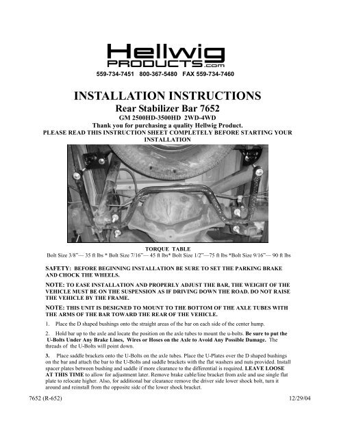
Rear Stabilizer Bar <strong>7652</strong><br />
GM <strong>2500</strong>HD-<strong>3500HD</strong> 2WD-4WD<br />
Thank you for purchasing a quality Hellwig Product.<br />
PLEASE READ THIS INSTRUCTION SHEET COMPLETELY BEFORE STARTING YOUR<br />
INSTALLATION<br />
TORQUE TABLE<br />
Bolt Size 3/8”— 35 ft lbs * Bolt Size 7/16”— 45 ft lbs* Bolt Size 1/2”—75 ft lbs *Bolt Size 9/16”— 90 ft lbs<br />
SAFETY: BEFORE BEGINNING INSTALLATION BE SURE TO SET THE PARKING BRAKE<br />
AND CHOCK THE WHEELS.<br />
NOTE: TO EASE INSTALLATION AND PROPERLY ADJUST THE BAR, THE WEIGHT OF THE<br />
VEHICLE MUST BE ON THE SUSPENSION AS IF DRIVING DOWN THE ROAD. DO NOT RAISE<br />
THE VEHICLE BY THE FRAME.<br />
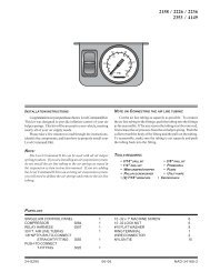
NOTE: THIS UNIT IS DESIGNED TO MOUNT TO THE BOTTOM OF THE AXLE TUBES WITH<br />
THE ARMS OF THE BAR TOWARD THE REAR OF THE VEHICLE.<br />
1. Place the D shaped bushings onto the straight areas of the bar on each side of the center hump.<br />
2. Hold bar up to the axle and locate the position on the axle tubes to mount the u-bolts. Be sure to put the<br />
U-Bolts Under Any Brake Lines, Wires or Hoses on the Axle to Avoid Any Possible Damage. The<br />
threads of the U-Bolts will point down.<br />
3. Place saddle brackets onto the U-Bolts on the axle tubes. Place the U-Plates over the D shaped bushings<br />
on the bar and attach the bar to the U-Bolts and saddle brackets with the flat washers and nuts provided. Install<br />
spacer plates between bushing and saddle if more clearance to the differential is required. LEAVE LOOSE<br />
AT THIS TIME to allow for adjustment later. Remove brake cable/line bracket from axle and use single flat<br />
plate to relocate higher. Also, for additional bar clearance remove the driver side lower shock bolt, turn it<br />
around and reinstall from the opposite side of the lower shock bracket.<br />
<strong>7652</strong> (R-652) 12/29/04
559-734-7451 800-367-5480 FAX 559-734-7460<br />
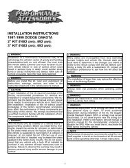
Driver’s Side<br />
Passenger Side<br />
4. Locate existing spare tire crossmember on vehicle frame. Place square U-bolt over the frame rail in front of the crossmember<br />
with legs of the U-bolt pointing downward.<br />
5. Insert the legs of the U-bolt into slotted holes of the frame brackets. Using 1/2” locknuts and washers, install the frame<br />
bracket with the centered clevis on the driver side of vehicle as shown in photos. Install the frame bracket with the offset<br />
clevis on passenger side of vehicle as shown in photos. LEAVE LOOSE for adjustment later. ( FINAL TIGHTENING<br />
ON FRAME U-BOLTS TORQUE TO 40 FT. LBS. )<br />
6. Insert hourglass bushing and sleeve into end link assembly. Lubricate the bushing and sleeve to ease assembly.<br />
7. Attach end links to clevis on frame bracket as shown using the 7/16 x 2 1/4” bolts. LEAVE LOOSE for adjustment later.<br />
8. Raise bar ends upward to be level with the frame and attach end links to sway bar ends as shown in photos using the hardware<br />
provided. Use the 1/2” lock nut on the end of the end link assembly.<br />
9. Align bar from side to side through the D-bushings to be as centered as possible. Rotate bar front to rear by rotating the U-<br />
Bolts on the axle. Adjust frame brackets so that the end-links are straight up and down as possible. Be sure the bar does<br />
not contact the differential, shocks, or leaf springs.<br />
10. Torque all of the mounting hardware to the specified rates. Bounce vehicle, checking for clearance on all undercarriage<br />
components, ie: exhaust, shocks, fuel lines, brake lines, etc. Recheck installation periodically on a regular basis.<br />
ATTENTION INSTALLER: PLEASE MAKE SURE CUSTOMER RECEIVES THIS INSTRUCTION<br />
SHEET,ALL IMPORTANT NOTE CARDS, WARNING CARDS AND THE<br />
WARRANTY FORM<br />
<strong>7652</strong> (R-652) 12/29/04