Installation Instructions - Air Lift
Installation Instructions - Air Lift
Installation Instructions - Air Lift

Create successful ePaper yourself
Turn your PDF publications into a flip-book with our unique Google optimized e-Paper software.
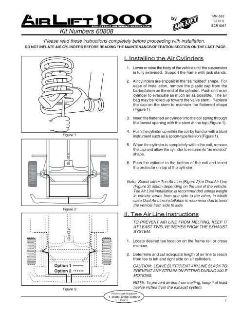
3. Slide air line clamp onto the air line (Figures 4 and 5).4. Push the air line over one side of the tee until all thebarbs are covered. Repeat procedure for other legof tee (Figures 5).5. With pliers, slide the air line clamp forward until itfully covers the barbed section. Repeat for otherleg of tee (Figures 5).6. Route air line along cross member and upper springseat to left and right air cylinder.7. Insert air line through spring seat protector and slideon the air line clamp (Figure 4).AFigure 4C8. Push the air line onto the barbed cylinder stem,covering all the barbs (Figure 4).9. With pliers, slide the air line clamp downward until itfully covers the barbed section.B<strong>Air</strong> LineClamp10. Push the remaining air line over the last fitting ontee and route along frame to desired inflation valvelocation (Figure 2). Attach with plastic straps orwire.11. Select a location for inflation valve in the gas capwell, the trunk, rear bumper, fender flange or behindthe license plate. Insure that the valve will beprotected and accessible with an air hose.Use this procedure for all line connections:A. Slide air line clamp onto the air lineB. Push the air line over the barbed stem.C. Compress the ears on the air line clamp with pliersand slide it forward to fully cover the barbedsection.Figure 5FlatWasherHex NutVehicle Bumperor BodyHex NutRubberWasherLockWasherFigure 6<strong>Air</strong> Line<strong>Air</strong> LineClampInflationValve12. Drill a 5/16” hole for inflation valve and mount asillustrated in Figure 6. The rubber washer is foroutside weather seal.13. Slide air line clamp over the air line. Push air lineonto fitting covering all barbs. With pliers slide theair line clamp forward until it fully covers the barbedsection (Figure 8).II. Dual <strong>Air</strong> Line RoutingNOTE: To prevent air line from melting, keep itat least eight inches from exhaust system.1. Select a location for the inflation valves in thegas cap well, the trunk, rear bumper, fenderflange or behind the license plate. Insure thateach valve will be protected and accessible withan air line.2. Determine and cut an adequate length of air lineto reach from the valve location to the left sideair cylinder.NOTE: Do not cut the air line longer that 90”.2Technical Support1-800-248-0892Ext. 2
CAUTION: LEAVE SUFFICIENT AIR LINESLACK TO PREVENT ANY STRAIN ON VALVESTEM DURING NORMAL AXLE MOTIONS.<strong>Air</strong> Line Cutting3. Insert the air line through the spring seat protectorand slide on the air line clamp (Figure 4).4. Push the air line onto the barbed cylinder stem,covering all the barbs (Figure 4).6. With pliers, slide the air line clamp forward untilit fully covers the barbed section.7. Route the air line along the frame or under thefender panel to the desired inflation valvelocation (Figure 6). Attach the air line to thechassis with plastic straps or wire.Good CutFigure 7Poor Cut8. Drill 5/16” hole for inflating valves and mount asillustrated. The rubber washer is for outsideweather seal (Figure 6).9. Slide air clamp over the air line. Push the air lineover the fitting, covering all the barbs (Figure 8).11. With pliers slide the air line clamp forward untilit fully covers the barbed section (Figure 8).Figure 812. Repeat the process for the right side.III. Installing the Heat ShieldsNOTE: Check exhaust clearance and insure thatit is 2-3 inches from the air cylinder.1. The heat shields are installed on the exhaustpipe at the closest point to the air spring to protectthe unit from the radiant heat of the exhaustsystem.2. Attach the radiator clamps loosely around theexhaust pipe nearest to the air spring.Figure 93. Bend the heat shield tab out at a 90° angle toform an “L” shape. Repeat on the other tab (Figure9). Position the heat shield and insert the heatshield tabs beneath the two radiator clamps.Tighten the clamps (Figure 9).4. Bend the heat shield to form it around the tailpipe. Be sure to maintain a “dead air” space of1/2” to 1” between the tail pipe and the heat shield(Figure 10).NOTE: Make sure installation does not interferewith moving parts, gas lines, etc."Dead air space"Exhaust Pipe5. Install a heat shield on both sides of the cylinder/spring (Figure 9).Figure 10Technical Support1-800-248-0892Ext. 2 3
Continued from pg. 1Guidelines for adding air:1. Start with the vehicle level or slightly above.2. When in doubt, always add air.3. For motorhomes, start with 50-100 PSI in the rear because it can be safely assumed that it is heavily loaded.4. If the front of the vehicle dives while braking, increase the pressure in the front air bags, if equipped.5. If it is ever suspected that the air bags have bottomed out, increase the pressure (fig. 4).6. Adjust the pressure up and down to find the best ride.7. If the vehicle rocks and rolls, adjust the air pressure to reduce movement.8. It may be necessary to maintain different pressures on each side of the vehicle. Loads such as water, fuel,and appliances will cause the vehicle to be heavier on one side (fig. 5). As much as a 50 PSI difference is notuncommon.Bottoming out fig. 4 Unlevel Levelfig. 5Warranty and Returns Policy<strong>Air</strong> <strong>Lift</strong> Company warrants its products, for the time periods listed below, to the original retail purchaser against manufacturing defects whenused on catalog-listed applications on cars, vans, light trucks and motorhomes under normal operating conditions for as long as <strong>Air</strong> <strong>Lift</strong>manufactures the product. The warranty does not apply to products that have been improperly applied, improperly installed, used in racingor off-road applications, used for commercial purposes, or which have not been maintained in accordance with installation instructionsfurnished with all products. The consumer will be responsible for removing (labor charges) the defective product from the vehicle andreturning it, transportation costs prepaid, to the dealer from which it was purchased or to <strong>Air</strong> <strong>Lift</strong> Company for verification.<strong>Air</strong> <strong>Lift</strong> will repair or replace, at its option, defective products or components. A minimum $10.00 shipping and handling charge will apply toall warranty claims. Before returning any defective product, you must call <strong>Air</strong> <strong>Lift</strong> at (800) 248-0892 in the U.S. and Canada (elsewhere, (517)322-2144) for a Returned Materials Authorization (RMA) number. Returns to <strong>Air</strong> <strong>Lift</strong> can be sent to: <strong>Air</strong> <strong>Lift</strong> Company • 2727 Snow Road •Lansing, MI • 48917.Product failures resulting from abnormal use or misuse are excluded from this warranty. The loss of use of the product, loss of time,inconvenience, commercial loss or consequential damages is not covered. The consumer is responsible for installation/reinstallation (laborcharges) of the product. <strong>Air</strong> <strong>Lift</strong> Company reserves the right to change the design of any product without assuming any obligation to modifyany product previously manufactured.This warranty gives you specific legal rights and you may also have other rights that vary from state-to-state. Some states do not allowlimitations on how long an implied warranty lasts or allow the exclusion or limitation of incidental or consequential damages. The abovelimitation or exclusion may not apply to you. There are no warranties, expressed or implied including any implied warranties of merchantabilityand fitness, which extend beyond this warranty period. There are no warranties that extend beyond the description on the face hereof. Sellerdisclaims the implied warranty of merchantability. (Dated proof of purchase required.)<strong>Air</strong> <strong>Lift</strong> 1000............................... Lifetime LimitedRideControl................................ Lifetime LimitedSlam<strong>Air</strong>...................................... Lifetime LimitedLoad<strong>Lift</strong>er 5000*........................ Lifetime LimitedEasyStreet Systems..................... 1 Year LimitedLoad Controller (I)........................ 2 Year LimitedLoad Controller (II)....................... 2 Year LimitedSmart<strong>Air</strong>........................................ 2 Year LimitedWireless AIR................................. 2 Year LimitedOther Accessories....................... 2 Year Limited*formerly SuperDuty Rev. 4/5/07Thank you for purchasing <strong>Air</strong> <strong>Lift</strong> products! For technical support, please call (800) 248-0892.<strong>Air</strong> <strong>Lift</strong> Company • P.O. Box 80167, MI 48908-0167 • (517) 322-2144 • Fax: (517) 322-0240 • www.airliftcompany.com