View - Rough Country
View - Rough Country
View - Rough Country

Create successful ePaper yourself
Turn your PDF publications into a flip-book with our unique Google optimized e-Paper software.
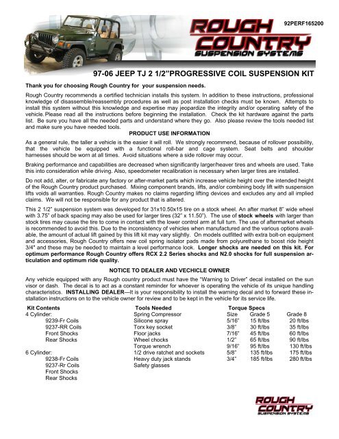
92PERF165200<br />
Kit Contents<br />
4 Cylinder:<br />
9239-Fr Coils<br />
9237-RR Coils<br />
Front Shocks<br />
Rear Shocks<br />
6 Cylinder:<br />
9238-Fr Coils<br />
9237-Rr Coils<br />
Front Shocks<br />
Rear Shocks<br />
97-06 JEEP TJ 2 1/2”PROGRESSIVE COIL SUSPENSION KIT<br />
Thank you for choosing <strong>Rough</strong> <strong>Country</strong> for your suspension needs.<br />
<strong>Rough</strong> <strong>Country</strong> recommends a certified technician installs this system. In addition to these instructions, professional<br />
knowledge of disassemble/reassembly procedures as well as post installation checks must be known. Attempts to<br />
install this system without this knowledge and expertise may jeopardize the integrity and/or operating safety of the<br />
vehicle. Please read all the instructions before beginning the installation. Check the kit hardware against the parts<br />
list. Be sure you have all the needed parts and understand where they go. Also please review the tools needed list<br />
and make sure you have needed tools.<br />
PRODUCT USE INFORMATION<br />
As a general rule, the taller a vehicle is the easier it will roll. We strongly recommend, because of rollover possibility,<br />
that the vehicle be equipped with a functional roll-bar and cage system. Seat belts and shoulder<br />
harnesses should be worn at all times. Avoid situations where a side rollover may occur.<br />
Braking performance and capabilities are decreased when significantly larger/heaver tires and wheels are used. Take<br />
this into consideration while driving. Also, speedometer recalibration is necessary when larger tires are installed.<br />
Do not add, alter, or fabricate any factory or after-market parts which increase vehicle height over the intended height<br />
of the <strong>Rough</strong> <strong>Country</strong> product purchased. Mixing component brands, lifts, and/or combining body lift with suspension<br />
lifts voids all warranties. <strong>Rough</strong> <strong>Country</strong> makes no claims regarding lifting devices and excludes any and all implied<br />
claims. We will not be responsible for any product that is altered.<br />
This 2 1/2” suspension system was developed for 31x10.50x15 tire on a stock wheel. An after market 8” wide wheel<br />
with 3.75” of back spacing may also be used for larger tires (32” x 11.50”). The use of stock wheels with larger than<br />
stock tires may cause the tire to come in contact with the lower control arm at full turn. The use of aftermarket wheels<br />
is recommended to avoid this. Due to the inconsistency of vehicles when manufactured and the various options available,<br />
the amount of actual lift gained by this lift kit may vary slightly. On models outfitted with extra bolt-on equipment<br />
and accessories, <strong>Rough</strong> <strong>Country</strong> offers new coil spring isolator pads made from polyurethane to boost ride height<br />
3/4" and these may be needed to maintain a level performance look. Longer shocks are needed on this kit. For<br />
optimum performance <strong>Rough</strong> <strong>Country</strong> offers RCX 2.2 Series shocks and N2.0 shocks for full suspension articulation<br />
and optimum ride quality.<br />
NOTICE TO DEALER AND VECHICLE OWNER<br />
Any vehicle equipped with any <strong>Rough</strong> country product must have the “Warning to Driver” decal installed on the sun<br />
visor or dash. The decal is to act as a constant reminder for whoever is operating the vehicle of its unique handling<br />
characteristics. INSTALLING DEALER—It is your responsibility to install the warning decal and to forward these installation<br />
instructions on to the vehicle owner for review and to be kept in the vehicle for its service life.<br />
Tools Needed<br />
Spring Compressor<br />
Silicone spray<br />
Torx key socket<br />
Floor jacks<br />
Wheel chocks<br />
Torque wrench<br />
1/2 drive ratchet and sockets<br />
Heavy duty jack stands<br />
Safety glasses<br />
Torque Specs<br />
Size Grade 5 Grade 8<br />
5/16” 15 ft/lbs 20 ft/lbs<br />
3/8” 30 ft/lbs 35 ft/lbs<br />
7/16” 45 ft/lbs 60 ft/lbs<br />
1/2” 65 ft/lbs 90 ft/lbs<br />
9/16” 95 ft/lbs 130 ft/lbs<br />
5/8” 135 ft/lbs 175 ft/lbs<br />
3/4” 185 ft/lbs 280 ft/lbs
FRONT INSTALLATION INSTRUCTIONS<br />
1. The front-end components are installed first.<br />
2. Place the vehicle on a level surface. Set the parking brake. Center the front wheels and chock rear wheels.<br />
3. From inside the engine compartment, remove the upper stud nut, retainer and grommet from both of the front<br />
shocks.<br />
4. Place jack stands on the frame rail behind the lower control arm mount on the frame and jack up the vehicle. Installation<br />
is done one side at a time.<br />
5. Remove the front tires and wheels.<br />
6. Remove the sway bar links from the axle using a 18mm wrench / T55 torx head bit to allow the axle to be lowered<br />
for coil spring removal. See Photo 1.<br />
7. Place a floor jack underneath the axle for support and complete the removal of the front shock absorbers. Retain<br />
factory lower mounting hardware for re-use.<br />
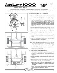
8. Remove the coil spring clip located on the bottom coil seat as shown in Photo 2 using a 13mm wrench on the<br />
driver side of the vehicle. Lower the axle and remove the coil spring.<br />
PHOTO 1 PHOTO 2<br />
9. Install the new front progressive rate coil spring. A coil spring or strut compressor may be needed for the new coil<br />
spring installation. Install the new coil spring (with the coil wraps that are closer together to the top) into the upper<br />
and lower spring pockets and carefully remove the compressor. Make sure the coil is seated properly in the<br />
coil seat by rotating the spring so the pig tail end fits in the spring pocket. Install the coil spring clamp and torque<br />
the spring clip bolt to 16ft.-lbs.<br />
10. Install the front shock absorber in the factory upper &lower mounts. (Longer shocks are highly recommended<br />
for this lift). Please Note 2.2 shocks will install with the body up and the 2.0 will install with the body<br />
down.<br />
11. Repeat installation on the opposite side of the vehicle.<br />
12. Install the tires, wheels and lug nuts and tighten to factory specifications. Lower the vehicle to the ground<br />
13. Reinstall the sway bar links in the factory location with factory hardware using a 18mm wrench and T55 torx head<br />
bit.
REAR INSTALLATION INSTRUCTIONS<br />
1. Chock the front wheels. Jack up the rear of the vehicle<br />
and remove the tires and wheels.<br />
2. Place jack stands under the frame rail to support the vehicle.<br />
Place a floor jack under the differential to lightly support<br />
the axle.<br />
3. Remove the stock shock absorbers. Retain the hardware<br />
for reuse.<br />
4. Remove the lower sway bar links from the sway bar using<br />
a 15mm wrench. See Photo 4 . Retain the factory hardware<br />
for re-installation.<br />
3. Carefully lower the axle with the floor jack and remove the<br />
coil springs. NOTE: It may be necessary to use a coil<br />
spring or strut compressor to remove the stock coil<br />
springs. Be careful not to overextend the vent tube on the<br />
axle. It may be necessary to disconnect the vent tube<br />
during installation and reroute the vent tube after installation<br />
to ensure the line does not get damaged.<br />
4. Install the new <strong>Rough</strong> <strong>Country</strong> progressive rate coil<br />
springs making sure the coil isolator is positioned in the<br />
upper mount. It may be necessary to use a coil spring or<br />
strut compressor to install the new coil springs. See<br />
Photo 5. <strong>Rough</strong> <strong>Country</strong>’s New RCX 2.2 series shock is<br />
also pictured. Please Note 2.2 shocks will install with<br />
the body up and the 2.0 will install with the body<br />
down.<br />
5. Jack up the axle to lightly compress the coil springs.<br />
6. Install the rear shock absorber in the factory mounts with<br />
the factory hardware using a 15mm & 18mm wrench for<br />
the lower and a 13mm socket for the upper. Tighten hardware.<br />
(Longer shocks are highly recommended for<br />
2.2 Shocks Shown<br />
this lift).<br />
7. Install the wheels and tires and lower the vehicle to the floor.<br />
8. Reinstall the factory sway bar links with the factory hardware using a 15mm wrench and tighten.<br />
PHOTO 4<br />
PHOTO 5
POST INSTALLATION INSTRUCTIONS<br />
1. Check the transfer case shifter to see if it will move to 4L. If<br />
not, the linkage will need adjusting. Place the shifter in 4L,<br />
loosen adjustment bolt and push the linkage forward until it<br />
stops. Now re-tighten adjustment bolt. See Photo 1. Check to<br />
be sure 4WD works properly.<br />
2. Rotate driveshaft and check for interference at differential<br />
yoke and cardan joint. If necessary, lightly dress casting(s)<br />
and/or U-joint tabs in order to eliminate binding<br />
3. Have a qualified alignment center realign front end to factory<br />
specifications.<br />
4. Install Warning to Driver decal on sun visor.<br />
5. Adjust headlights to proper settings.<br />
PHOTO 1<br />
MAINTENANCE INFORMATION<br />
It is the ultimately the buyers responsibility to have all bolts/nuts checked for tightness after the first 500 miles and<br />
then every 1000 miles or 3 months. Wheel alignment steering system, suspension and driveline systems must be<br />
inspected by a qualified professional mechanic at least every 3000 miles.<br />
TROUBLESHOOTING TIPS<br />
Problem: Driveline Vibrations<br />
Possible Solution: Check all u-joints to insure that there is no wear on the existing hardware caps. Even a new vehicle<br />
can cause vibrations in the angle on the U-joint is changed after being run for even a short period of time.<br />
Possible Solution: Driveline vibrations can be caused from the removal or addition of the hardtop which changes the<br />
rear vehicle weight, and the rear height, which affects the rear drive shaft pinion angle. If excessive vibration occurs,<br />
<strong>Rough</strong> <strong>Country</strong>’s adjustable eccentric upper cam-bolt kit will eliminate such vibrations by adjusting /<br />
rotating the rear pinion angle up or down as needed.<br />
Problem: On 03-06 models equipped with the automatic transmission, the transmission skid plate may come<br />
in contact with the front driveshaft at full droop even when equipped with the 1” lowering spacers supplied.<br />
Possible Solution: Lower the transmission skid plate more to create distance in between the driveshaft & skid plate<br />
or remove the skid plate from the vehicle.<br />
FRONT COILS<br />
REAR COILS<br />
2.2 SHOCK ABSORBERS SHOWN<br />
Thank you for purchasing a <strong>Rough</strong> <strong>Country</strong> Suspension Lift Kit.
92115700<br />
97-06 JEEP TJ 1 1/4” BODY LIFT KIT<br />
Congratulations on your purchase of a new <strong>Rough</strong> <strong>Country</strong> 1 1/4” Body Lift. We are committed to providing<br />
you with the best product available for the best value. Your satisfaction is our highest priority!<br />
<strong>Rough</strong> <strong>Country</strong> recommends a certified technician installs this system. In addition to these instructions, professional<br />
knowledge of disassemble/reassembly procedures as well as post installation checks must be known. Check the kit<br />
hardware against the parts list. Be sure you have all the needed parts and understand where they go. Also please<br />
review the tools needed list and make sure you have needed tools.<br />
PRODUCT USE INFORMATION<br />
As a general rule, the taller a vehicle is the easier it will roll. We strongly recommend, because of rollover possibility,<br />
that the vehicle be equipped with a functional roll-bar and cage system. Seat belts and shoulder harnesses should be<br />
worn at all times. Avoid situations where a side rollover may occur.<br />
Do not add, alter, or fabricate any factory or after-market parts which increase vehicle height over the intended height<br />
of the <strong>Rough</strong> <strong>Country</strong> product purchased. We will not be responsible for any product that is altered.<br />
This 1 1/4” body lift kit can be used with <strong>Rough</strong> <strong>Country</strong>’s lift kit if desired to allow the fitment of larger tires for off<br />
road use.<br />
NOTICE TO DEALER AND VECHICLE OWNER<br />
Any vehicle equipped with any <strong>Rough</strong> <strong>Country</strong> product must have the “Warning to Driver” decal installed on the sun<br />
visor or dash. The decal is to act as a constant reminder for whoever is operating the vehicle of its unique handling<br />
characteristics.<br />
BODY LIFT PRE INSTALLATION NOTES:<br />
To ensure the SRS system (Air bag system) is not accidentally deployed during installation, always ground yourself<br />
and the vehicle. Exercise extreme caution when working near SRS sensors and wiring. DO not allow anyone near air<br />
bags during the lift kit installation. Accidental deployment can result in serious injury or death. As a precaution, the<br />
negative and positive wire should be disconnected from the battery with the negative wire being removed first. Also<br />
the air bag fuse can be removed from the fuse panel behind the glove box. Check hoses and wiring before and<br />
recheck during installation taking caution to not overextend them.<br />
Kit Contents :<br />
11-1 1/4” Body Pucks<br />
6-1/2” x 4 1/2” bolts<br />
6-1/2” Flat Washers<br />
5-7/16” x 4” Bolts<br />
5-7/16” Flat Washers<br />
2-5/16” x 3/4” Self Tapping Bolts<br />
2-Fr Brackets<br />
1-Shift Control Bracket<br />
1-Shift Control Poly Bag:<br />
2 --1/4” x 3/4” bolts<br />
4--1/4” Washers<br />
2--1/4” Nuts<br />
Torque Specs:<br />
Size Grade 5 Grade 8<br />
7/16” 45 ft/lbs 60 ft/lbs<br />
1/2” 65 ft/lbs 90 ft/lbs<br />
1/4” 12 ft/lbs 18 ft/lbs<br />
Class 8.8 Class 10.9<br />
6MM 5 ft/lbs 9 ft/lbs<br />
Tools Needed:<br />
Floor jacks, Wood Blocks, Wheel chocks, Torque wrench, 1/2 drive ratchet<br />
5/8” socket/wrench, 3/4” socket /wrench, Safety glasses, Thread locker
BODY LIFT INSTALLATION INSTRUCTIONS<br />
1. Make sure the vehicle is on a level smooth surface.<br />
2. Loosen the 11 body bolts using a 5/8” socket. Do not remove the stock bolts at this time.<br />
3. Remove the front body mount bolt as shown in Photo 1. Remove either the 5 passenger side bolts or the 5 driver<br />
side bolts. Do not remove both sides. Installation is performed one side at a time.<br />
4. Using a floor jack slowly jack up the body of the Jeep and insert the supplied body lift blocks between the body<br />
and the three side cab mount bushings as shown in Photo 2. Take caution to keep your hands out from between<br />
the frame and the body. The three side body mounts will be secured with the supplied 1/2” x 4 1/2” bolts. Apply<br />
thread locker to the bolts and install. Do not tighten at this time.<br />
Photo 1<br />
5. Insert the supplied body lift blocks in the 4 rear most mounts. Apply thread locker to the supplied 7/16” x 4” bolts<br />
and install. Photo 3 shows all body mounts. Rear corner mount shown in Photo 4. Do not tighten at this time.<br />
Photo 3<br />
Photo 4<br />
6. Place the new radiator core support bracket in place and mark hole to be drilled. See Photo 5.<br />
7. Drill the hole using a 9/32” drill bit. See Photo 6.<br />
8. Secure using the bracket to the frame with the supplied 5/16” x 1” self tapping bolt. Tighten using a 1/2” wrench.<br />
Photo 5 Photo 6
9. Slowly lower the body onto the body mounts.<br />
10. Proceed to opposite side and install the body lift blocks<br />
as installed on the previous side.<br />
11. Install the front body spacer as shown in Photo 7.<br />
Apply thread locker to the supplied 7/16 x 4” bolt and<br />
install.<br />
12. Tighten all body bolts to 30-35 ft/lbs. Do not over<br />
tighten. Over tightening the body mount bolts could<br />
crush the factory body mounts.<br />
13. Remove the fan from the motor as shown in Photo 8<br />
using a 1/2” wrench. Save the hardware for reuse.<br />
14. Remove the power steering reservoir from the fan<br />
shroud to allow it to be removed<br />
15. Remove the fan shroud using a 7/16” wrench. See<br />
Photo 9. Save the factory hardware for reuse.<br />
Photo 7<br />
Photo 8 Photo 9<br />
Photo 2<br />
16. Measure 1 1/4” up as shown in Photo 10 and drill the shroud using a 1/4” bit. The lower passenger side hole<br />
will line up with an existing factory hole and will not require marking with a center punch. On 6 cylinder models,<br />
it may be necessary to remove a small portion of the fan shroud webbing to allow the 1/4” hole to be drilled.<br />
17. Test fit the fan shroud to the radiator by aligning with the new mounting holes and mark the location where the<br />
lower radiator hose interferes with the fan shroud. Trim the fan shroud until it completely clears the radiator hose<br />
when mounted to the radiator. Reinstall the fan with factory hardware using a 1/2” wrench and check for<br />
interference between the fan shroud and fan blades, or any other objects, and trim the fan shroud accordingly.<br />
18. Secure the shroud to the factory location with factory hardware using a 7/16” wrench. Tighten all hardware.<br />
Photo 10 Photo 11
TRANSFER CASE SHIFTER BRACKET INSTALLATION INSTRUCTIONS<br />
These next steps will be necessary if the vehicle is equipped with a transfer case drop kit. If the vehicle does<br />
NOT have a transfer case kit installed the bracket should NOT be installed. The bracket is designed to adjust<br />
the 4WD shifter allowing the full range of the shift pattern. After drop bracket installation, check the<br />
operation of the 4WD shift lever to ensure the transfer case engages fully in all ranges. Additional “fine<br />
tuning” can be performed if the shifter does not fully engage in all the ranges. Refer to instructions on the<br />
next page to adjust the shift linkage. It may also be necessary to trim the body under the middle console to<br />
avoid interference with the shifter.<br />
1. From underneath the vehicle, locate the shift control bracket. It is attached to the inside of the transmission tunnel<br />
on the driver side and acts as a pivot for the transfer case shift lever.<br />
2. Remove the shifter linkage from the shifter plate that is mounted on the body tunnel as shown using a 10 mm<br />
wrench.<br />
3. Reinstall the stock shifter bracket on the new drop<br />
bracket as shown with the 1/4” x 3/4” hardware. Tighten<br />
using a 7/16” wrench. See Photo 1.<br />
4. Install the supplied drop bracket on the stock tunnel<br />
bracket with the supplied 1/4” x 3/4” bolts/washers &<br />
nuts. Tighten hardware using a 7/16” wrench. Check<br />
clearance on bolts. See Photo 1.<br />
Due to factory variations on the shifter rod bracket, it<br />
may be necessary to modify the shifter bracket by<br />
slightly bending the mount on the rod to clear the shifter<br />
bracket or shifter bracket bolts. After noting how much<br />
to bend the bracket to clear, remove the shifter<br />
assembly and bend the bracket as shown to slightly<br />
clear the bracket / bolts. Do not over-bend!! See Photo 2.<br />
Bracket Installation Photo 1<br />
Before<br />
Photo 2<br />
After<br />
SHIFTER LINKAGE ADJUSTMENT INSTRUCTIONS<br />
If the 4WD shifter engages in all ranges, the following<br />
procedure will NOT be necessary.<br />
1. Check the transfer case shifter to see if it will move to 4L. If<br />
not, the linkage will need adjusting. Place the shifter in 4L,<br />
loosen adjustment bolt and push the linkage forward until it<br />
stops. Now re-tighten adjustment bolt. See Photo 1. Check to<br />
be sure 4WD works properly.<br />
Photo 1<br />
MAINTENANCE INFORMATION<br />
It is the ultimately the buyers responsibility to have all bolts/nuts checked for tightness after the first 500 miles and<br />
then every 1000 miles or 3 months. Wheel alignment steering system, suspension and driveline systems must be<br />
inspected by a qualified professional mechanic at least every 3000 miles.