

Single Pole (One location) or 3-Way (Multi-location) Quiet Fan ...
Single Pole (One location) or 3-Way (Multi-location) Quiet Fan ...
Single Pole (One location) or 3-Way (Multi-location) Quiet Fan ...

Create successful ePaper yourself
Turn your PDF publications into a flip-book with our unique Google optimized e-Paper software.
DI-000-VZF01-02C<br />
WarnInGS anD CautIonS:<br />
• To be installed and/<strong>or</strong> used in acc<strong>or</strong>dance with appropriate electrical codes and regulations.<br />
• If you are unsure about any part of these instructions, consult a qualified electrician.<br />
• To avoid overheating and possible damage to this device and other equipment, do not install to control a receptacle, flu<strong>or</strong>escent lighting, a mot<strong>or</strong> <strong>or</strong> a<br />
transf<strong>or</strong>mer-operated appliance other than appropriate ceiling fans.<br />
• To reduce risk of fire <strong>or</strong> electrical shock, this control is to be used with ceiling fans that are rated 120VAC, total load 1.5 amperes maximum.<br />
• F<strong>or</strong> use on ceiling paddle fans with split-capacit<strong>or</strong> <strong>or</strong> shaded pole mot<strong>or</strong>s only. Please refer to manufacturer’s instructions <strong>or</strong> rating label on the mot<strong>or</strong> to<br />
confirm type. Use with any other types of mot<strong>or</strong>s <strong>or</strong> equipment may cause overheating and/<strong>or</strong> damage to the mot<strong>or</strong>s <strong>or</strong> equipment.<br />
tools needed to install your <strong>Fan</strong> Speed Control:<br />
Slotted/Phillips Screwdriver Electrical Tape<br />
Pliers Pencil<br />
Cutters Ruler<br />
Changing the col<strong>or</strong> of your <strong>Fan</strong> Speed Control:<br />
Your fan speed control includes three col<strong>or</strong> options. The fan speed<br />
controller ships with the White frame attached. To change col<strong>or</strong> of frame,<br />
proceed as follows:<br />
MaXIMuM loaD PEr <strong>Fan</strong> SPEED Control F<strong>or</strong> MultI-DEVICE<br />
Cat. no.<br />
VZFØ1<br />
Push in side at<br />
tab to release<br />
<strong>Single</strong><br />
1.5A<br />
line up tabs and<br />
press in side to attach<br />
Installing <strong>Fan</strong> Speed Control by itself <strong>or</strong> with<br />
other devices:<br />
If installing fan speed control in a single device application, proceed with<br />
the InStallInG Your <strong>Fan</strong> SPEED Control section. If installing fan<br />
speed control in a multi-device application, proceed as follows:<br />
MultI-DEVICE aPPlICatIon<br />
In multi-fan speed control installations, there is no derating necessary.<br />
Refer to the chart f<strong>or</strong> maximum load per fan speed control.<br />
two Devices<br />
1.5A<br />
M<strong>or</strong>e than<br />
2 Devices<br />
1.5A<br />
InStallInG Your <strong>Fan</strong> SPEED Control<br />
notE: Use check boxes when Steps are completed.<br />
Step 1<br />
Step 2<br />
1<br />
3<br />
4<br />
<strong>Single</strong> <strong>Pole</strong><br />
1. Line (Hot)<br />
2. Neutral<br />
3. Ground<br />
4. Load<br />
���<br />
���<br />
���<br />
���<br />
���<br />
���<br />
��<br />
��<br />
��<br />
��<br />
��<br />
��<br />
���<br />
���<br />
���<br />
���<br />
���<br />
���<br />
��<br />
��<br />
��<br />
��<br />
��<br />
��<br />
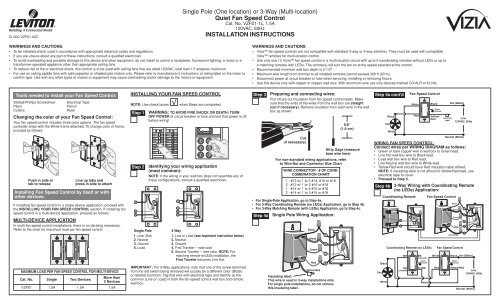
<strong>Single</strong> <strong>Pole</strong> (<strong>One</strong> <strong>location</strong>) <strong>or</strong> 3-<strong>Way</strong> (<strong>Multi</strong>-<strong>location</strong>)<br />
<strong>Quiet</strong> <strong>Fan</strong> Speed Control<br />
Cat. No. VZFØ1-1L, 1.5A<br />
120VAC, 60Hz<br />
InStallatIon InStruCtIonS<br />
WarnInG: to aVoID FIrE SHoCK <strong>or</strong> DEatH; turn<br />
oFF PoWEr at circuit breaker <strong>or</strong> fuse and test that power is off<br />
bef<strong>or</strong>e wiring!<br />
Identifying your wiring application<br />
(most common):<br />
notE: If the wiring in your wall box does not resemble any of<br />
these configurations, consult a qualified electrician.<br />
2<br />
1<br />
3<br />
4<br />
5<br />
IMPORTANT : F<strong>or</strong> 3-<strong>Way</strong> applications, note that one of the screw terminals<br />
from the old switch being removed will usually be a different col<strong>or</strong> (Black)<br />
<strong>or</strong> labeled Common. Tag that wire with electrical tape and identify as the<br />
common (Line <strong>or</strong> Load) in both the fan speed control wall box and remote<br />
wall box.<br />
2<br />
3-<strong>Way</strong><br />
1. Line <strong>or</strong> Load (see imp<strong>or</strong>tant instruction below)<br />
2. Neutral<br />
3. Ground<br />
4. First Traveler – note col<strong>or</strong><br />
5. Second Traveler – note col<strong>or</strong>. notE: F<strong>or</strong><br />
matching remote w/LEDs installation, the<br />
First traveler becomes Line Hot.<br />
WarnInGS anD CautIonS:<br />
• Vizia fan speed controls are not compatible with standard 3-way <strong>or</strong> 4-way switches. They must be used with compatible<br />
Vizia remotes f<strong>or</strong> multi-<strong>location</strong> control.<br />
• Use only one (1) Vizia fan speed control in a multi-<strong>location</strong> circuit with up to 9 co<strong>or</strong>dinating remotes without LEDs <strong>or</strong> up to<br />
4 matching remotes with LEDs. The remote(s) will turn the fan on at the speed selected at the control.<br />
• Recommended minimum wall box depth is 2-1/2".<br />
• Maximum wire length from dimmer to all installed remotes cannot exceed 300 ft (90 m).<br />
• Disconnect power at circuit breaker <strong>or</strong> fuse when servicing, installing <strong>or</strong> removing fixture.<br />
• Use this device only with copper <strong>or</strong> copper clad wire. With aluminum wire use only devices marked CO/ALR <strong>or</strong> CU/AL.<br />
Step 3<br />
Preparing and connecting wires:<br />
Pull off pre-cut insulation from fan speed control leads. Make<br />
sure that the ends of the wires from the wall box are straight<br />
(cut if necessary). Remove insulation from each wire in the wall<br />
box as shown:<br />
Cut<br />
(if necessary)<br />
F<strong>or</strong> non-standard wiring applications, refer<br />
to Wire nut and Connect<strong>or</strong> Size Chart<br />
WIrE ConnECt<strong>or</strong> / # oF ConD.<br />
CoMBInatIon CHart<br />
1 - #12 w/ 1 to 3 #14, #16 <strong>or</strong> #18<br />
2 - #12 w/ 1 <strong>or</strong> 2 #16 <strong>or</strong> #18<br />
1 - #14 w/ 1 to 4 #16 <strong>or</strong> #18<br />
2 - #14 w/ 1 to 3 #16 <strong>or</strong> #18<br />
5/8"<br />
(1.6 cm)<br />
Strip Gage (measure<br />
bare wire here)<br />
• F<strong>or</strong> <strong>Single</strong>-<strong>Pole</strong> application, go to Step 4a.<br />
• F<strong>or</strong> 3-<strong>Way</strong> Co<strong>or</strong>dinating remote (no lEDs) application, go to Step 4b.<br />
• F<strong>or</strong> 3-<strong>Way</strong> Matching remote (with lEDs) application, go to Step 4c.<br />
Step 4a<br />
<strong>Single</strong> <strong>Pole</strong> Wiring application:<br />
Black<br />
White<br />
Green<br />
red<br />
Yellow/red<br />
Insulating label:<br />
this wire is used in 3-way installations only.<br />
F<strong>or</strong> single pole installations, do not remove<br />
this insulating label.<br />
1<br />
2<br />
3<br />
4<br />
Step 4a cont'd<br />
<strong>Fan</strong><br />
Black<br />
White<br />
<strong>Fan</strong> Speed Control<br />
White<br />
Red<br />
Black<br />
Green<br />
Ground<br />
Yellow/<br />
Red<br />
Insulating<br />
Label<br />
Hot (Black)<br />
Line<br />
120VAC, 60Hz<br />
Neutral (White)<br />
WIrInG <strong>Fan</strong> SPEED Control:<br />
Connect wires per WIrInG DIaGraM as follows:<br />
• Green <strong>or</strong> bare copper wire in wall box to Green lead.<br />
• Line Hot wall box wire to Black lead.<br />
• Load wall box wire to Red lead.<br />
• Line Neutral wall box wire to White lead.<br />
• Yellow/Red wire should have Red insulation label affixed.<br />
notE: If insulating label is not affixed to Yellow/Red lead, use<br />
electrical tape to cover.<br />
• Proceed to Step 5.<br />
Step 4b<br />
<strong>Fan</strong><br />
Black<br />
White<br />
3-<strong>Way</strong> Wiring with Co<strong>or</strong>dinating remote<br />
(no lEDs) application:<br />
Co<strong>or</strong>dinating Remote<br />
BK WH<br />
YL/RD RD<br />
3<br />
5<br />
Co<strong>or</strong>dinating Remote (no LEDs)<br />
WH<br />
RD<br />
(unused)<br />
1<br />
2<br />
4<br />
BK<br />
(unused)<br />
Green<br />
Ground<br />
YL/RD<br />
<strong>Fan</strong> Speed Control<br />
<strong>Fan</strong> Speed Control<br />
White Black Hot (Black)<br />
Red<br />
Black<br />
White<br />
Green<br />
Red<br />
Yellow/Red<br />
Green<br />
Ground<br />
Yellow/Red<br />
1<br />
2<br />
3<br />
4<br />
5<br />
Line<br />
120VAC, 60Hz<br />
Neutral (White)
Step 4b cont'd 3-<strong>Way</strong> Wiring with Co<strong>or</strong>dinating remote Step 4c cont'd<br />
(no lEDs) application:<br />
WIrInG <strong>Fan</strong> SPEED Control:<br />
Connect wires per WIrInG DIaGraM as follows:<br />
notE: When using the co<strong>or</strong>dinating remote without LEDs, the fan speed<br />
control can be installed on either the Line <strong>or</strong> Load side of the 3-way<br />
circuit.<br />
notE: Maximum wire length from fan speed control to all installed<br />
remotes cannot exceed 300 ft (90 m).<br />
• Green <strong>or</strong> bare copper wire in wall box to Green lead.<br />
• Line Hot (common) wall box wire identified (tagged) when removing<br />
old switch to Black lead.<br />
• First Traveler wall box wire to Red lead (note wire col<strong>or</strong>).<br />
• Remove Red insulating label from Yellow/Red lead.<br />
• Second Traveler wall box wire to Yellow/Red lead (note wire col<strong>or</strong>).<br />
This traveler from the fan speed control must go to the terminal screw<br />
on the remote marked "YL/RD".<br />
• Line Neutral wall box wire to White lead.<br />
WIrInG Co<strong>or</strong>DInatInG rEMotE:<br />
Connect wires per WIrInG DIaGraM as follows:<br />
notE: "BK" and "RD" terminals on co<strong>or</strong>dinating remote are unused.<br />
Tighten both screws.<br />
notE: Maximum wire length from fan speed control to last remote is<br />
300 ft (90 m).<br />
• Green <strong>or</strong> bare copper wire in wall box to Green terminal screw.<br />
• Load wall box wire identified (tagged) when removing old switch to<br />
First Traveler (note col<strong>or</strong> as above).<br />
• Second Traveler wall box wire (note col<strong>or</strong> as above) to terminal<br />
screw marked "YL/RD". This traveler from the remote must go to the<br />
Yellow/Red fan speed control lead.<br />
• Remove White insulating label from terminal screw marked "WH".<br />
• Line Neutral wall box wire to terminal screw marked "WH".<br />
• Proceed to Step 5.<br />
Step 4c<br />
Matching remote<br />
BK WH<br />
Yl/rD rD<br />
2<br />
1<br />
4<br />
3<br />
5<br />
additional<br />
neutral Wire<br />
Matching Remote (with LEDs)<br />
Hot (Black)<br />
Line<br />
120VAC, 60Hz<br />
Neutral (White)<br />
3-<strong>Way</strong> Wiring with Matching remote<br />
(w/lEDs) application:<br />
WH<br />
BK<br />
Green<br />
Ground<br />
YL/RD<br />
<strong>Fan</strong> Speed Control<br />
Black<br />
White<br />
Green<br />
red<br />
Yellow/red<br />
<strong>Fan</strong> Speed control<br />
White<br />
Black<br />
Green<br />
Ground<br />
Red Yellow/Red<br />
4<br />
2<br />
3<br />
1<br />
5<br />
Black<br />
White<br />
<strong>Fan</strong><br />
3-<strong>Way</strong> Wiring with Matching remote<br />
(w/lEDs) application:<br />
notE: The fan speed control must be installed in a wall box that has a<br />
Load connection. The matching remote must be installed in a wall box<br />
with a Line Hot connection and a Neutral connection. A Neutral wire to the<br />
matching remote needs to be added as shown.<br />
If you are unsure about any part of these instructions, consult a qualified<br />
electrician.<br />
notE: Maximum wire length from fan speed control to all installed remotes<br />
cannot exceed 300 ft (90 m).<br />
WIrInG MatCHInG rEMotE<br />
(wall box with line Hot connection):<br />
Connect wires per WIrInG DIaGraM as follows:<br />
• Green <strong>or</strong> bare copper wire in wall box to Green terminal screw.<br />
• Line Hot (common) wall box wire identified (tagged) when removing old<br />
switch and First Traveler to fan speed control Black lead.<br />
• Second Traveler wall box wire from fan speed control to remote<br />
terminal screw marked "YL/RD" (note wire col<strong>or</strong>). This traveler from the<br />
remote must go to the fan speed control Yellow/Red lead.<br />
• Line Neutral wall box to remote terminal screw marked "WH".<br />
WIrInG <strong>Fan</strong> SPEED Control<br />
(wall box with load connection):<br />
Connect wires per WIrInG DIaGraM as follows:<br />
• Green <strong>or</strong> bare copper wire in wall box to Green lead.<br />
• Load wall box wire identified (tagged) when removing old switch to Red<br />
lead.<br />
• First Traveler Line Hot to Black lead.<br />
• Remove Red insulating label from Yellow/Red lead.<br />
• Second Traveler wall box wire (note col<strong>or</strong> as above) to Yellow/Red lead.<br />
This traveler from the fan speed control must go to the terminal screw on<br />
the remote marked "YL/RD".<br />
• Line neutral wall box wire to White lead.<br />
• Proceed to Step 5.<br />
Step 5 testing your <strong>Fan</strong> Speed Control pri<strong>or</strong> to<br />
mounting in wall box:<br />
• Position all wires to<br />
provide room in outlet<br />
wall box f<strong>or</strong> device.<br />
• Ensure that the w<strong>or</strong>d<br />
“TOP” is facing up on<br />
device strap.<br />
• Partially screw in<br />
mounting screws in wall<br />
box mounting holes.<br />
notE: Dress wires with a<br />
bend as shown in diagram<br />
in <strong>or</strong>der to relieve stress<br />
when mounting device.<br />
• Rest<strong>or</strong>e power at circuit breaker <strong>or</strong><br />
fuse.<br />
• Press pad until locat<strong>or</strong> light is OFF.<br />
<strong>Fan</strong> should turn ON. If fan does not<br />
turn ON, press the upper half of the<br />
<strong>Fan</strong> Speed Bar until the fan turns ON.<br />
If fan still does not turn on, refer to<br />
the trouBlESHootInG section.<br />
oPEratIon<br />
notE: The locat<strong>or</strong> light will illuminate when the load is in the OFF position<br />
to facilitate access in the dark.<br />
notE: If using the fan speed control in a 3-way application, the fan will turn<br />
ON at speed set on fan’s <strong>Fan</strong> Speed bar. The fan speed can be controlled<br />
from either the fan speed control <strong>or</strong> the remote <strong>location</strong>.<br />
air-Gap Switch:<br />
On the <strong>Fan</strong> Speed Control only, engage the air-gap<br />
switch by gently pulling the bottom of the push pad<br />
until it lifts completely out of the frame and a click<br />
is heard. refer to figure. This will cut power to the<br />
fixture. After servicing is complete, push the push<br />
pad back f<strong>or</strong> n<strong>or</strong>mal operation.<br />
Cleaning: Clean with a damp cloth.<br />
Do not use chemical cleaners.<br />
Push Pad (Default settings)<br />
turn on from oFF position:<br />
Tap – <strong>Fan</strong> turns ON to preset speed.<br />
turn oFF from on position:<br />
Tap – <strong>Fan</strong> turns OFF.<br />
<strong>Fan</strong> Speed Bar<br />
Press <strong>Fan</strong> Speed Bar up <strong>or</strong> down to increase <strong>or</strong><br />
decrease fan speed respectively.<br />
There are 3 speeds - High, Medium <strong>or</strong> Low.<br />
InCrEaSE:<br />
Press the top half of the <strong>Fan</strong> Speed Bar to<br />
increase fan speed.<br />
DECrEaSE:<br />
Press the bottom half of the <strong>Fan</strong> Speed Bar to<br />
decrease fan speed.<br />
If you continue to hold, the fan will reduce<br />
speed to minimum level and then turn OFF.<br />
notE: When the fan is OFF you can change<br />
the fan speed that the fan will turn ON to using<br />
the <strong>Fan</strong> Speed Bar.<br />
If there is a power outage, when the power is<br />
rest<strong>or</strong>ed, the fan will return to the last setting<br />
bef<strong>or</strong>e the power interruption.<br />
Gently lift bottom<br />
of push pad out<br />
F<strong>or</strong> additional inf<strong>or</strong>mation, contact leviton’s techline<br />
at 1-800-824-3005 <strong>or</strong> visit leviton’s website at<br />
www.leviton.com<br />
Covered by one <strong>or</strong> m<strong>or</strong>e US & F<strong>or</strong>eign<br />
Patents and patents pending<br />
Copyright© 2006 Leviton Manufacturing Co., Inc.<br />
All Rights Including Trade Dress Rights Reserved<br />
DI-000-VZF01-02C<br />
lIMItED 5 YEar WarrantY anD EXCluSIonS<br />
Leviton warrants to the <strong>or</strong>iginal consumer purchaser and not f<strong>or</strong> the benefit of anyone else that this product at the time of its sale by Leviton is free of defects in materials and w<strong>or</strong>kmanship under n<strong>or</strong>mal and proper use f<strong>or</strong> five years from the purchase date. Leviton’s only obligation is to c<strong>or</strong>rect such defects by repair <strong>or</strong> replacement,<br />
at its option, if within such five year period the product is returned prepaid, with proof of purchase date, and a description of the problem to leviton Manufacturing Co., Inc., att: Quality assurance Department, 59-25 little neck Parkway, little neck, new Y<strong>or</strong>k 11362-2591. This warranty excludes and there is disclaimed<br />
liability f<strong>or</strong> lab<strong>or</strong> f<strong>or</strong> removal of this product <strong>or</strong> reinstallation. This warranty is void if this product is installed improperly <strong>or</strong> in an improper environment, overloaded, misused, opened, abused, <strong>or</strong> altered in any manner, <strong>or</strong> is not used under n<strong>or</strong>mal operating conditions <strong>or</strong> not in acc<strong>or</strong>dance with any labels <strong>or</strong> instructions. there are<br />
no other <strong>or</strong> implied warranties of any kind, including merchantability and fitness f<strong>or</strong> a particular purpose, but if any implied warranty is required by the applicable jurisdiction, the duration of any such implied warranty, including merchantability and fitness f<strong>or</strong> a particular purpose, is limited to five years. leviton is not liable f<strong>or</strong> incidental,<br />
indirect, special, <strong>or</strong> consequential damages, including without limitation, damage to, <strong>or</strong> loss of use of, any equipment, lost sales <strong>or</strong> profits <strong>or</strong> delay <strong>or</strong> failure to perf<strong>or</strong>m this warranty obligation. The remedies provided herein are the exclusive remedies under this warranty, whether based on contract, t<strong>or</strong>t <strong>or</strong> otherwise.<br />
Step 6<br />
Step 7<br />
lED <strong>Fan</strong><br />
Speed<br />
Display<br />
Push<br />
Pad<br />
<strong>Fan</strong> Speed Control Mounting:<br />
turn oFF PoWEr at CIrCuIt BrEaKEr <strong>or</strong> FuSE.<br />
rest<strong>or</strong>e Power:<br />
Rest<strong>or</strong>e power at circuit breaker <strong>or</strong> fuse.<br />
Installation is complete.<br />
<strong>Fan</strong><br />
Speed<br />
Bar<br />
locat<strong>or</strong><br />
light<br />
Installation may now be completed by<br />
tightening mounting screws into wall box.<br />
Attach wallplate.<br />
aDVanCED ProGraMMInG FEaturES<br />
Set Speed lock: Set the fan speed that the fan will turn ON to<br />
regardless of the previous fan speed at which it was turned OFF.<br />
advanced Features Summary<br />
Description<br />
range<br />
Set Speed-Lock Level<br />
LED<br />
<strong>Fan</strong> Speed<br />
Display<br />
trouBlESHootInG<br />
1<br />
4<br />
7<br />
0 - 100 %, 0 = no lock<br />
High<br />
Medium<br />
Low<br />
• <strong>Fan</strong> does not turn on and on/oFF lED does not turn on<br />
- Circuit breaker <strong>or</strong> fuse has tripped.<br />
- <strong>Fan</strong> has burned out.<br />
- <strong>Fan</strong> Neutral connection is not wired.<br />
Default<br />
to Program:<br />
1. On the <strong>Fan</strong> Speed Control only, engage<br />
the air-gap switch by gently pulling<br />
the bottom of the push pad until it lifts<br />
completely out of the frame and a click<br />
is heard. refer to figure.<br />
2. Press push pad back into frame and<br />
hold f<strong>or</strong> 7 seconds until the locat<strong>or</strong> light<br />
and LED 1, located at top, start blinking.<br />
3. Upon releasing the push pad, the<br />
locat<strong>or</strong> light will continue to blink twice<br />
per second indicating the <strong>Fan</strong> Speed<br />
Control is in Set Speed Lock mode.<br />
4. To change the current Speed Lock level<br />
use the <strong>Fan</strong> Speed Bar to move the<br />
LED to the desired preset level. The setting will automatically be saved<br />
by tapping the push pad to exit programming mode.<br />
The LED Brightness Display is separated into 3 segments. Each LED group<br />
represents a preset level with LED 1 (High) located at the top and LED 7<br />
(Low) located at the bottom. Refer to chart f<strong>or</strong> settings and defaults.<br />
notE: The <strong>Fan</strong> Speed Control will exit program mode after 3 minutes of<br />
inactivity.<br />
0


