

Multisaw 1400 / 1600 / 2000 / 2400 & HXF3300 ... - McConnel
Multisaw 1400 / 1600 / 2000 / 2400 & HXF3300 ... - McConnel
Multisaw 1400 / 1600 / 2000 / 2400 & HXF3300 ... - McConnel

Create successful ePaper yourself
Turn your PDF publications into a flip-book with our unique Google optimized e-Paper software.
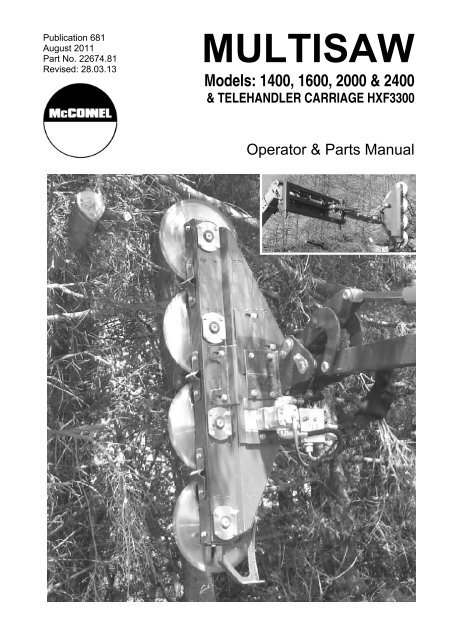
Publication 681<br />
August 2011<br />
Part No. 22674.81<br />
Revised: 28.03.13<br />
MULTISAW<br />
Models: <strong>1400</strong>, <strong>1600</strong>, <strong>2000</strong> & <strong>2400</strong><br />
& TELEHANDLER CARRIAGE <strong>HXF3300</strong><br />
Operator & Parts Manual
IMPORTANT<br />
VERIFICATION OF WARRANTY REGISTRATION<br />
DEALER WARRANTY INFORMATION & REGISTRATION VERIFICATION<br />
It is imperative that the selli ng dealer registers this machine with <strong>McConnel</strong> Limited before<br />
delivery to the end user – failure to do so may affect the validity of the machine warranty.<br />
To register machines go to t he <strong>McConnel</strong> Limited web site at www.mcconnel.com, log<br />
onto ‘Dealer Inside’ and select the ‘ Machine Registration button’ which can be found in<br />
the Service Section of the si te. Confirm to the customer that the machine has bee n<br />
registered in the section below.<br />
Should you experience any problems registering a machine in this manner p lease contact<br />
the <strong>McConnel</strong> Service Department on 01584 875848.<br />
Registration Verification<br />
Dealer Name: ……………………..…………………………………………………………….<br />
Dealer Address: …….………………………………………………………………………….<br />
Customer Name: ……………………..…………………………………………………………<br />
Date of Warranty Registration: ……/……/...…… Dealer Signature: ………………..……<br />
NOTE TO CUSTOMER / OWNER<br />
Please ensure that the above section above has been completed and signed by the selling<br />
dealer to verify that your machine has been registered with <strong>McConnel</strong> Limited.<br />
IMPORTANT: During the initial ‘bedding in’ period of a new machine it is the customer’s responsibility<br />
to regularly inspect all nuts, bolts and hose connections for tightness and re-tighten if required. New<br />
hydraulic connections occasionally weep small amounts of oil as the seals and joints settle in – where<br />
this occurs it can be cured by re-tightening the connection – refer to torque settings chart below. The<br />
tasks stated above should be performed on an hourly basis during the first day of work and at least<br />
daily thereafter as part of the machines general maintenance procedure.<br />
TORQUE SETTINGS FOR HYDRAULIC FITTINGS<br />
HYDRAULIC HOSE ENDS<br />
PORT ADAPTORS WITH BONDED SEALS<br />
BSP Setting Metric BSP Setting Metric<br />
1/4” 18 Nm 19 mm 1/4” 34 Nm 19 mm<br />
3/8” 31 Nm 22 mm 3/8” 47 Nm 22 mm<br />
1/2” 49 Nm 27 mm 1/2” 102 Nm 27 mm<br />
5/8” 60 Nm 30 mm 5/8” 122 Nm 30 mm<br />
3/4” 80 Nm 32 mm 3/4” 149 Nm 32 mm<br />
1” 125 Nm 41 mm 1” 203 Nm 41 mm<br />
1.1/4” 190 Nm 50 mm 1.1/4” 305 Nm 50 mm<br />
1.1/2” 250 Nm 55 mm 1.1/2” 305 Nm 55 mm<br />
2” 420 Nm 70 mm 2” 400 Nm 70 mm
WARRANTY POLICY<br />
WARRANTY REGISTRATION<br />
All machines must be registered, by the selling dealer with <strong>McConnel</strong> Ltd, before delivery to the end<br />
user. On receipt of the goods it is the buyer’s re sponsibility to check that the Verification of Warranty<br />
Registration in the Operator’s Manual has been completed by the selling dealer.<br />
1. LIMITED WARRANTIES<br />
1.01. All machines supplied by <strong>McConnel</strong> Limited are warranted to be free from defects in material<br />
and workmanship from the date of sal e to the original purchaser for a period of 1 2 months,<br />
unless a different period is specified.<br />
1.02. All spare parts supplied by <strong>McConnel</strong> Limited are warranted to be free from defects in material<br />
and workmanship from the date of sale to the original purchaser for a period of 6 months.<br />
1.03. The manufacturer will replace or rep air for the p urchaser any part or pa rts found, upon<br />
examination at its factory, to be defective under normal use a nd service due to defects in<br />
material or workmanship. Returned parts must be complete and unexamined.<br />
1.04. This warranty does not apply to any part of the goods, which has been subjected to improper or<br />
abnormal use, negligence, alteration, modification, fitment of non-genuine parts, accid ent<br />
damage, or damage resulting from contact with overhead power lines, dam age caused by<br />
foreign objects (e.g. stones, iron, ma terial other than vegetati on), failure due to lack of<br />
maintenance, use of incorrect oil or lubricants, contamination of the oil, or which has served its<br />
normal life. This warranty does not ap ply to any expendable items such as blades, flails, flap<br />
kits, skids, soil engaging parts, shields, guards, wear pads or pneumatic tyres.<br />
1.05. Temporary repairs an d consequential loss - i.e. oil, do wntime and associated parts are<br />
specifically excluded from the warranty.<br />
1.06. Warranty on hoses is limit ed to 12 months and does not include hoses w hich have suffere d<br />
external damage. Only complete hoses may be returned under warranty, any which have been<br />
cut or repaired will be rejected.<br />
1.07. Machines must be repaired immediately a problem arises. Continued use of the machine after a<br />
problem has occurred can result in furt her component failures, for which <strong>McConnel</strong> Ltd ca nnot<br />
be held liable, and may have safety implications.<br />
1.08. Except as provided herein, no employee, agent, dealer or other person is authorised to give any<br />
warranties of any nature on behalf of <strong>McConnel</strong> Ltd.<br />
1.09. For machine warranty periods in excess of 12 months the follo wing additional exclusions shall<br />
apply:<br />
1) Hoses, external seals, exposed pipes and hydraulic tank breathers.<br />
2) Filters.<br />
3) Rubber mountings.<br />
4) External electric wiring.<br />
1.10. All service work, particularly filter c hanges, must be carried out in accordance with the<br />
manufacturer’s service schedule. Failure to comply will invalidate the warranty. In the event of a<br />
claim, proof of the service work being carried out may be required.<br />
NB Warranty cover will be invalid if any non-genuine parts have been fitted or used. Use of<br />
non-genuine parts may seriously affect the machine’s performance and safety. <strong>McConnel</strong> Ltd<br />
cannot be held responsible for any failures or safety implications that arise due to the use of<br />
non-genuine parts.
2. REMEDIES AND PROCEDURES<br />
2.01. The warranty is not effective unless the Selling Dealer registers the machine, via the <strong>McConnel</strong><br />
web site and confirms the registration to the purchaser by completing the confirmation form in<br />
the operator’s manual.<br />
2.02. Any fault must be reported to an authorised <strong>McConnel</strong> dealer as soon as it o ccurs. Continued<br />
use of a m achine, after a f ault has occurred, can result in further component failure for which<br />
<strong>McConnel</strong> Ltd cannot be held liable.<br />
2.03. Repairs should be undertaken within two days of the failure. Claims submitted for re pairs<br />
undertaken more than 2 weeks after a failure ha s occurred, or 2 days after the pa rts were<br />
supplied will be rejected, unless the delay has been authorised by <strong>McConnel</strong> Ltd.<br />
2.04. All claims must be submitted, by an aut horised <strong>McConnel</strong> Service Dealer, within 30 days of the<br />
date of repair.<br />
2.05. Following examination of the claim an d parts the manufacture will pay, at their discretio n, for<br />
any valid claim the cost of any parts and an appropriate labour allowance if applicable.<br />
2.06. The submission of a claim is not a guarantee of payment.<br />
2.07. Any decision reached by <strong>McConnel</strong> Ltd. is final.<br />
3. LIMITATION OF LIABILITY<br />
3.01. The manufacturer disclaims any express (exc ept as set forth herein) an d implied warranties<br />
with respect to the goods including, but not limited to, merchantability and fitness for a particular<br />
purpose.<br />
3.02. The manufacturer makes no warranty as to the design, capability, capacity or suitability for use<br />
of the goods.<br />
3.03. Except as provi ded herein, the m anufacturer shall have no liability or responsibility to the<br />
purchaser or any other person or entity with respect to any liability, loss, or damage caused o r<br />
alleged to be caused directly or indirectly by the goods including, but not limited to, any indirect,<br />
special, consequential, or incidental damages resulting from the use or operation of the goods<br />
or any breach of this warranty. Notwithstanding the above limitations and warranties, the<br />
manufacturer’s liability hereund er for d amages incurred by the purchase r or others shall not<br />
exceed the price of the goods.<br />
3.04. No action arising out of any claimed breach of this warranty or transactions under this warranty<br />
may be brought more than one (1) year after the cause of the action has occurred.<br />
4. MISCELLANEOUS<br />
4.01. The manufacturer may waive compliance with any of the terms of this limited warranty, but no<br />
waiver of any terms shall be deemed to be a waiver of any other term.<br />
4.02. If any provision of this limited warranty shall violate any applic able law and is held to be<br />
unenforceable, then the invalidity of such provis ion shall not invalidate any other provisions<br />
herein.<br />
4.03. Applicable law may provide rights an d benefits to the purchaser in addition to those provided<br />
herein.
DECLARATION OF CONFORMITY<br />
Conforming to EU Machinery Directive 2006/42/EC<br />
We,<br />
McCONNEL LIMITED, Temeside Works, Ludlow, Shropshire SY8 1JL, UK<br />
Hereby declare that:<br />
The Product; Hydraulic Arm Mounted Sawhead<br />
Product Code; MTSW<br />
Serial No. & Date ………………………………… Type …………………………<br />
Manufactured in; Denmark<br />
Complies with the required provisions of the Machinery Directive 2006/42/EC<br />
The machinery directive is supported by the following harmonized standards;<br />
BS EN ISO 14121-1 (2007) Safety of machinery - Risk assessment, Part 1:<br />
Principles Part 2: practical guide and examples of methods.<br />
BS EN ISO 12100-1 (2010) Safety of mach inery - Part 1: Basic terminology and<br />
methodology Part 2: Technical principles.<br />
BS EN 349(1993)+ A1 (2008) Safety of machinery - Minimum distances to avoid the<br />
entrapment with human body parts.<br />
BS EN 953 (1998) Safety of machinery - Guards General requirements for the<br />
design and construction of fixed and movable guards.<br />
BS EN 982(1996)+ A1 (2008) Safety requirements for fluid power systems and their<br />
components. Hydraulics<br />
McCONNEL LIMITED operates an IS O 9001:2008 quality management system,<br />
certificate number: FM25970.<br />
This system is continually assessed by the;<br />
British Standards Institution (BSI), Beech House, Milton Keynes, MK14 6ES, UK<br />
BSI is accredited by UK Accreditation Service, accreditation number: UKAS 003.<br />
The EC declaration only applies if the machine stated above is used in<br />
accordance with the operating instructions.<br />
Signed …………………................ Responsible Person<br />
CHRISTIAN DAVIES on behalf of McCONNEL LIMITED<br />
Status: General Manager Date: May 2011
CONTENTS<br />
Operation Section<br />
General Information 2<br />
Safety Information 3<br />
Safety Decals 7<br />
Vehicle Preparation 8<br />
<strong>Multisaw</strong> Overview 9<br />
<strong>Multisaw</strong> Installation 10<br />
<strong>Multisaw</strong> Operation 11<br />
<strong>Multisaw</strong> Maintenance 12<br />
<strong>HXF3300</strong> Mounting Carriage 14<br />
<strong>HXF3300</strong> Attachment 14<br />
<strong>HXF3300</strong> Transport & Work Position 15<br />
<strong>HXF3300</strong> Operation 16<br />
<strong>HXF3300</strong> Valves & Electrics 16<br />
<strong>HXF3300</strong> Maintenance 19<br />
Parts Section<br />
Main Assembly - <strong>Multisaw</strong> <strong>1400</strong> Model 24<br />
Blade Assembly - <strong>Multisaw</strong> <strong>1400</strong> Model 26<br />
Motor Plate Assembly - <strong>Multisaw</strong> <strong>1400</strong> Model 28<br />
Tensioner Assembly - <strong>Multisaw</strong> <strong>1400</strong> Model 29<br />
Main Assembly - <strong>Multisaw</strong> <strong>1600</strong> Model 30<br />
Drive Assembly - <strong>Multisaw</strong> <strong>1600</strong> Model 32<br />
Blade Unit - <strong>Multisaw</strong> <strong>1600</strong> Model 34<br />
Main Frame - <strong>Multisaw</strong> <strong>2000</strong> / <strong>2400</strong> Models 36<br />
Blade Shaft - <strong>Multisaw</strong> <strong>2000</strong> / <strong>2400</strong> Models 38<br />
Adjusting System - <strong>Multisaw</strong> <strong>2000</strong> / <strong>2400</strong> Models 39<br />
Piston Motor - <strong>Multisaw</strong> <strong>2000</strong> / <strong>2400</strong> Models 40<br />
Machine Decals 41<br />
<strong>HXF3300</strong> Telehandler Carriage (for <strong>Multisaw</strong> <strong>2000</strong> / <strong>2400</strong> Models) 42<br />
Telehandler Carriage Valve 43<br />
1
GENERAL INFORMATION<br />
Always read this manual before fitting or operating the machine – whenever doubt exists<br />
contact your dealer or the <strong>McConnel</strong> Service Department for advice and assistance.<br />
Use only <strong>McConnel</strong> Genuine Service Parts on <strong>McConnel</strong> Equipment and Machines<br />
DEFINITIONS – The following definitions apply throughout this manual:<br />
WARNING<br />
An operating procedure, technique etc. which can result in personal injury or loss of life if not<br />
observed carefully.<br />
CAUTION<br />
An operating procedure, technique etc. which can result in damage to either machine or<br />
equipment if not observed carefully.<br />
NOTE<br />
An operating procedure, technique etc. which is considered essential to emphasis.<br />
LEFT AND RIGHT HAND<br />
This term is applicable to the machine when attached to the tractor and is viewed from the<br />
rear – this also applies to tractor references.<br />
MACHINE & DEALER INFORMATION<br />
Record the Serial Number of your machine on this page and always quote this number when<br />
ordering parts. Whenever information concerning the machine is requested remember also to state<br />
the make and model of tractor to which the machine is fitted.<br />
Machine Serial Number:<br />
Machine Model details:<br />
Dealer Name:<br />
Dealer Address:<br />
Dealer Telephone No:<br />
Dealer Email Address:<br />
Installation Date:<br />
Note: The illustrations in this manual are for instructional purposes only and may on occasion not<br />
show some components in their entirety. In some instances an illustration may appear slightly different<br />
to that of your particular model but the general procedure will be the same. E&OA.<br />
SERIAL PLATE<br />
The machine is fitted with a Serial Number Plate stating the manufacturers name, machine,<br />
serial number and weight – when ordering parts or requesting advice please quote the<br />
machine name and serial number as stated on the plate.<br />
2
This machine has the potential to be extremely dangerous - in the wrong hands it can kill or<br />
maim; It is therefore imperative that both owner and operator of the machine reads and<br />
understands the following section to ensure they are fully aware of the dangers that do, or<br />
may exist, and their responsibilities surrounding the use and operation of the machine.<br />
The operator of this machine is responsible not only for their own safety but equally for the<br />
safety of others who may come into the close proximity of the machine, as the owner you are<br />
responsible for both.<br />
When the machine is not in use it should be lowered to rest on the ground. In the event of<br />
any fault being detected with the machine’s operation it must be stopped immediately and<br />
not used again until the fault has been corrected by a qualified technician.<br />
POTENTIAL DANGERS ASSOCIATED WITH THE USE OF THIS MACHINE:<br />
▲ Being hit by debris thrown by rotating components.<br />
▲ Being hit by machine parts ejected through damage during use.<br />
▲ Being caught on a rotating power take-off (PTO) shaft.<br />
▲ Being caught in other moving parts i.e.: belts, pulleys and cutting heads.<br />
▲ Electrocution from Overhead Power Lines (by contact with or ‘flashover’ from).<br />
▲ Being hit by cutting heads or machine arms as they move.<br />
▲ Becoming trapped between tractor and machine when hitching or unhitching.<br />
▲ Tractor overbalancing when machine arm is extended.<br />
▲ Injection of high-pressure oil from hydraulic hoses or couplings.<br />
▲ Machine overbalancing when freestanding (out of use).<br />
▲ Road traffic accidents due to collision or debris on the road.<br />
3
BEFORE USING THIS MACHINE YOU MUST:<br />
▲ Ensure you read all sections of the operator handbook.<br />
▲ Ensure the operator is, or has been, properly trained to use the machine.<br />
▲ Ensure the operator has been issued with and reads the operator handbook.<br />
▲ Ensure the operator understands and follows the instructions in operator handbook.<br />
▲ Ensure the tractor front, rear and sides are fitted with metal mesh or polycarbonate<br />
guards of suitable size and strength to protect the operator against thrown debris or<br />
parts.<br />
▲ Ensure tractor guards are fitted correctly, are undamaged and kept properly maintained.<br />
▲ Ensure that all machine guards are in position, are undamaged, and are kept maintained<br />
in accordance with the manufacturer’s recommendations.<br />
▲ Ensure blades and their fixings are of a type recommended by the manufacturer, are<br />
securely attached and that none are missing or damaged.<br />
▲ Ensure hydraulic pipes are carefully and correctly routed to avoid damage by chaffing,<br />
stretching or pinching and that they are held in place with the correct fittings.<br />
▲ Always follow the manufacturer’s instructions for attachment and removal of the machine<br />
from the tractor.<br />
▲ Check that the machine fittings and couplings are in good condition.<br />
▲ Ensure the tractor meets the minimum weight recommendations of the machine’s<br />
manufacturer and that ballast is used as necessary.<br />
▲ Always inspect the work area thoroughly before starting to note obstacles and remove<br />
wire, bottles, cans and other debris.<br />
▲ Use clear suitably sized warning signs to alert others to the nature of the machine<br />
working within that area. Signs should be placed at both ends of the work site. (It is<br />
recommended that signs used are of a size and type specified by the Department of<br />
Transport and positioned in accordance with their, and the Local Highways Authority,<br />
guidelines).<br />
▲ Ensure the operator is protected from noise. Ear defenders should be worn and tractor<br />
cab doors and windows must be kept closed. Machine controls should be routed through<br />
proprietary openings in the cab to enable all windows to be shut fully.<br />
▲ Always work at a safe speed taking account of the conditions i.e.: terrain, highway<br />
proximity and obstacles around and above the machine. Extra special attention should be<br />
applied to Overhead Power Lines. Some of our machines are capable of reach in excess<br />
of 8 metres (26 feet) this means they have the potential to well exceed, by possibly 3<br />
metres (9’ 9”), the lowest legal minimum height of 5.2 metres from the ground for 11,000<br />
and 33,000 volt power lines. It cannot be stressed enough the dangers that surround this<br />
capability, it is therefore vital that the operator is fully aware of the maximum height and<br />
reach of the machine, and that they are fully conversant with all aspects regarding the<br />
safe minimum distances that apply when working with machines in close proximity to<br />
Power Lines. (Further information on this subject can be obtained from the Health &<br />
Safety Executive or your Local Power Company).<br />
4
▲ Always disengage the machine, kill the tractor engine, remove and pocket the key before<br />
dismounting for any reason.<br />
▲ Always clear up all debris left at the work area, it may cause hazard to others.<br />
▲ Always ensure when you remove your machine from the tractor that it is left in a safe and<br />
stable position using the stands and props provided and secured if necessary.<br />
WHEN NOT TO USE THIS MACHINE:<br />
▲ Never attempt to use this machine if you have not been trained to do so.<br />
▲ Never use a machine until you have read and understood the operator handbook, are<br />
familiar with it, and practiced the controls.<br />
▲ Never use a machine that is poorly maintained.<br />
▲ Never use a machine if guards are missing or damaged.<br />
▲ Never use a machine on which the hydraulic system shows signs of wear or damage.<br />
▲ Never fit, or use, a machine on a tractor that does not meet the manufacturer’s minimum<br />
specification level.<br />
▲ Never use a machine fitted to a tractor that does not have suitable front, rear and side(s)<br />
cab guarding made of metal mesh or polycarbonate.<br />
▲ Never use the machine if the tractor cab guarding is damaged, deteriorating or badly<br />
fitted.<br />
▲ Never turn a machine cutting head to an angle that causes debris to be ejected towards<br />
the cab.<br />
▲ Never start or continue to work a machine if people are nearby or approaching - Stop and<br />
wait until they are at a safe distance before continuing. WARNING: Some cutting heads<br />
may continue to ‘freewheel’ for up to 40 seconds or more after being stopped.<br />
▲ Never attempt to use a machine on materials in excess of its capability.<br />
▲ Never use a machine to perform a task it has not been designed to do.<br />
▲ Never operate the tractor or machine controls from any position other than from the<br />
driving seat, especially whilst hitching or unhitching the machine.<br />
▲ Never carry out maintenance of a machine or a tractor whilst the engine is running – the<br />
engine should be switched off, the key removed and pocketed.<br />
▲ Never leave a machine unattended in a raised position – it should be lowered to the<br />
ground in a safe position on a level firm site.<br />
▲ Never leave a tractor with the key in or the engine running.<br />
▲ Never carry out maintenance on any part or component of a machine that is raised<br />
unless that part or component has been properly substantially braced or supported.<br />
▲ Never attempt to detect a hydraulic leak with your hand – use a piece of cardboard.<br />
▲ Never allow children near to, or play on, a tractor or machine under any circumstances.<br />
5
ADDITIONAL SAFETY ADVICE<br />
Training<br />
Operators need to be competent and fully capable of operating this machine in a safe and<br />
efficient way prior to attempting to use it in any public place. We advise therefore that the<br />
prospective operator make use of relevant training courses available such as those run by<br />
the Agricultural Training Board, Agricultural Colleges, Dealers and <strong>McConnel</strong>.<br />
Working in Public Places<br />
When working in public places such as roadsides, consideration should be paid to others in<br />
the vicinity. Stop the machine immediately when pedestrians, cyclists and horse riders etc.<br />
pass. Restart only when they are at a distance that causes no risk to their safety.<br />
Warning Signs<br />
It is advisable that any working area be covered by suitable warning signs and statutory in<br />
public places. Signs should be highly visible and well placed in order to give clear advanced<br />
warning of the hazard. Contact the Department of Transport or your Local Highways<br />
Authority to obtain detailed information on this subject. The latter should be contacted prior<br />
to working on the public highway advising them of the time and location of the intended work<br />
asking what is required by way of signs and procedure. – ‘Non-authorised placement of road<br />
signs may create offences under the Highways Act’.<br />
Suggested Warning Signs Required<br />
‘Road works ahead’ warning sign with a supplementary ‘Hedge cutting’ plate. ‘For 1 mile’<br />
or appropriate shorter distance may be added to the plate.<br />
‘Road narrows’ warning signs with supplementary ‘Single file traffic’ plate.<br />
White on blue ‘Keep right’ (*) arrow sign on rear of machine.<br />
* Note – this applies to UK Market machines where traffic passes to the right of a machine working in<br />
the same direction as the traffic flow. The direction, use and colour of the arrow sign will depend on the<br />
country of use and the Local Highway Authorities regulations in the locality.<br />
Use of Warning Signs<br />
▲ On two-way roads one set of signs is needed facing traffic in each direction.<br />
▲ Work should be within 1 mile of the signs.<br />
▲ Work only when visibility is good and at times of low risk e.g.: NOT during ‘rush-hour’.<br />
▲ Vehicles should have an amber-flashing beacon.<br />
▲ Ideally, vehicles should be conspicuously coloured.<br />
▲ Debris should be removed from the road and path as soon as practicable, and at regular<br />
intervals, wearing high visibility clothing and before removing the hazard warning signs.<br />
▲ Collect all road signs promptly when the job is completed.<br />
Although the information stated here covers a wide range of safety subjects it is impossible to predict<br />
every eventuality that can occur under differing circumstances whilst operating this machine. No<br />
advice given here can replace ‘good common sense’ and ‘total awareness’ at all times, but will go a<br />
long way towards the safe use of your <strong>McConnel</strong> machine.<br />
6
SAFETY DECALS<br />
WARNING<br />
Pressurised oil, beware of leaks.<br />
Consult technical manual for<br />
service procedures.<br />
WARNING<br />
Stop engine and remove key<br />
before performing maintenance<br />
or repair work.<br />
WARNING<br />
Danger – flying objects. Keep a<br />
safe distance from the machine<br />
when the engine is running.<br />
WARNING<br />
Check tightness of bolts every 8<br />
hours – retighten if required.<br />
WARNING<br />
Danger - keep clear of rotating<br />
blades.<br />
WARNING<br />
Read the operator’s manual<br />
before handling or using the<br />
machine. Observe the safety<br />
rules when operating.<br />
WARNING<br />
Keep clear of the machines<br />
swing area.<br />
WARNING<br />
Danger - keep clear of overhead<br />
power lines.<br />
Where doubt exists, contact your<br />
local power company for advice.<br />
7
VEHICLE / TRACTOR PREPARATION<br />
We recommend vehicles are fitted with cabs<br />
using ‘safety glass’ windows and protective<br />
guarding when used with our machines.<br />
Fit Operator Guard (Part No. 7313324) using<br />
the hooks provided. Shape the mesh to cover<br />
all vulnerable areas. The driver must be<br />
looking through mesh and/or polycarbonate<br />
glazing when viewing the flail head in any<br />
working position - unless the vehicle/ cab<br />
manufacturer can demonstrate that the penetration resistance is equivalent to, or higher<br />
than, that provided by mesh/polycarbonate glazing. If the tractor has a roll bar only, a frame<br />
must be made to carry both mesh and polycarbonate glazing. The operator should also use<br />
personal protective equipment to reduce the risk of serious injury such as; eye protection<br />
(mesh visor to EN1731 or safety glasses to EN166), hearing protection to EN352, safety<br />
helmet to EN297, gloves, filter mask and high visibility clothing.<br />
Vehicle Ballast: It is imperative when attaching ‘third-party’ equipment to a vehicle that the<br />
maximum possible stability of the machine and vehicle combination is achieved – this can be<br />
accomplished by the utilisation of ‘ballast’ in order to counter-balance the additional<br />
equipment added.<br />
Front weights may be required for rear mounted machines to place 15% of total outfit<br />
weight on the front axle for stable transport on the road and to reduce ‘crabbing’ due to the<br />
drag of the cutting unit when working on the ground.<br />
Rear weights may be required to maintain a reasonable amount of rear axle load on the<br />
opposite wheel from the arms when in work; for normal off-ground work i.e. hedge cutting<br />
this should be 20% of rear axle weight or more for adequate control, and for ground work i.e.<br />
verge mowing with experienced operators, this can be reduced to 10%.<br />
All factors must be addressed in order to match the type and nature of the equipment added<br />
to the circumstances under which it will be used – in the instance of Power Arm hedgecutters<br />
it must be remembered that the machines centre of gravity during work will be constantly<br />
moving and will differ from that during transport mode, therefore balance becomes critical.<br />
Factors that effect stability:<br />
Centre of gravity of the tractor/machine combination.<br />
Geometric conditions, e.g. position of the cutting head and ballast.<br />
Weight, track width and wheelbase of the tractor.<br />
Acceleration, braking, turning and the relative position of the cutting head during these operations.<br />
Ground conditions, e.g. slope, grip, load capability of the soil/surface.<br />
Rigidity of implement mounting.<br />
Suggestions to increase stability:<br />
Increasing rear wheel track; a vehicle with a wider wheel track is more stable.<br />
Ballasting the wheel; it is preferable to use external weights but liquid can be added to around 75% of the tyre volume<br />
– water with anti-freeze or the heavier Calcium Chloride alternative can be used.<br />
Addition of weights – care should be taken in selecting the location of the weights to ensure they are added to a<br />
position that offers the greatest advantage.<br />
Front axle locking (check with tractor manufacturer).<br />
NOTE: The advice above is offered as a guide for stability only and is not a guide to vehicle strength. It<br />
is recommended that you consult your vehicle manufacturer or local dealer to obtain specific advice on<br />
this subject, additionally advice should be sought from a tyre specialist with regard to tyre pressures<br />
and ratings suitable for the type and nature of the machine you intend to fit.<br />
8
OVERVIEW<br />
<strong>McConnel</strong> <strong>Multisaw</strong>s <strong>1400</strong>, <strong>1600</strong>, <strong>2000</strong> & <strong>2400</strong> are a range of hydraulic arm mounted 4<br />
blade saw units used for the cutting of trees and branches. Available in widths of 1.4, 1.6, 2.1<br />
& 2.4m the machines are equipped with 340mm, 400mm, 500mm & 600mm ‘belt-driven’<br />
blades respectively.<br />
The machines have the following cutting capabilities;<br />
<strong>Multisaw</strong> <strong>1400</strong> up to 50mm diameter material (up to 70mm when cutting single branches)<br />
<strong>Multisaw</strong> <strong>1600</strong> up to 70mm diameter material (up to 100mm when cutting single branches)<br />
<strong>Multisaw</strong> <strong>2000</strong> up to 80mm diameter material (up to 120mm when cutting single branches)<br />
<strong>Multisaw</strong> <strong>2400</strong> up to 120mm diameter material (up to 160mm when cutting single branches)<br />
Best performance is achieved if the unit is angled at no more than 45° from the upright when<br />
vertical cutting.<br />
When working horizontally on hedges, best performance will be achieved on hedge widths of<br />
less than 100mm for the <strong>1400</strong> and <strong>1600</strong> models and less than 1200mm for the <strong>2000</strong> and<br />
<strong>2400</strong> models with branch diameters of up to 40mm; thicker diameter materials may cause<br />
the blades to stall or get stuck.<br />
SPECIFICATIONS<br />
Specification / Model <strong>Multisaw</strong> <strong>1400</strong> <strong>Multisaw</strong> <strong>1600</strong> <strong>Multisaw</strong> <strong>2000</strong> <strong>Multisaw</strong> <strong>2400</strong><br />
Working Width 1.4m 1.6m 2.1m 2.4m<br />
Blade Diameter 340mm 400mm 500mm 600mm<br />
Teeth per Blade 52 60 72 78<br />
Blade Material Hardened Steel Hardened Steel Hardened Steel Hardened Steel<br />
Blade Speed - 2600-2700RPM 3000-3200RPM 2700-2800RPM<br />
Oil Flow Rate 25 l/min 40 l/min 50 l/min 45 l/min<br />
Cutting Performance (single branch) Up to 70mm Up to 100mm Up to 120mm Up to 160mm<br />
Main Application Vertical Cutting Vertical Cutting Vertical Cutting Vertical Cutting<br />
Weight 45kg 98kg 220kg 280kg<br />
<strong>Multisaw</strong> <strong>1600</strong> Model<br />
<strong>Multisaw</strong> <strong>2000</strong> & <strong>2400</strong> Models<br />
9
INSTALLING THE MULTISAW<br />
Blades MUST be mounted in a downward cut rotation in relation to the tractors driving<br />
direction.<br />
Install and connect the hydraulic hoses ensuring the correct cutting direction is achieved.<br />
The separate drainage hose (max. 1.5 bar) must be led directly back to the oil reservoir.<br />
<br />
Check system for leaks.<br />
On initial installation the blade speed should be measured and the flow control valve<br />
adjusted to achieve the optimum working speeds of;<br />
2600-2700RPM for 1.6m models (<strong>Multisaw</strong> <strong>1600</strong>)<br />
3000-3200RPM for 2.1m models (<strong>Multisaw</strong> <strong>2000</strong>)<br />
2700-2800RPM for 2.4m models (<strong>Multisaw</strong> <strong>2400</strong>)<br />
10
MULTISAW OPERATION<br />
It is recommended that forward speed is kept to a minimum when starting work in order to<br />
retain the correct working speed of the blades. Set the angle of the <strong>Multisaw</strong> so it is<br />
positioned at right angles to the work and adjust the machine position so the branches meet<br />
the saw blades ‘straight on’.<br />
Should small branches or unwanted material get stuck in the blades the machine and tractor<br />
must be switched off and the debris cleared.<br />
Wherever possible try to keep the blades running vertical in relation to the direction of travel,<br />
this will help prevent them from ‘distorting’ during operations.<br />
A skid is available as an option which can be mounted on the base of the machine to prevent<br />
the blades from hitting the ground.<br />
When in charge of the machine always obey the following rules;<br />
Always inspect the work area prior to operation and remove any dangerous materials.<br />
Never operate the machine with persons or animals in close proximity.<br />
Ensure all cab guarding is in place and the tractor windows are kept shut.<br />
Only operate the machine at the correct blade speed.<br />
Never use the machine in excess of the maximum oil pressure in the hoses (250 bar, 210<br />
bar for <strong>1400</strong> models).<br />
Never stop the engine with the PTO engaged.<br />
<br />
<br />
Never transport the machine with the PTO engaged.<br />
Never transport the machine without the blade protection guards fitted.<br />
Never approach the machine when it is running, always switch it off and stop the tractor.<br />
Always remove the tractor ignition key before leaving the cab.<br />
Never use the machine to perform tasks it was not designed for.<br />
11
MULTISAW MAINTENANCE<br />
Initial Maintenance<br />
After an initial 2 hours work, re-tighten taper-lock bushes to 31 Nm.<br />
After the first day’s work, all bolts, screws and taper-lock bushes must be re-tightened - if<br />
the bushes loosen at a future time they should be secured with ‘Loctite’ or similar.<br />
Regular Maintenance<br />
Check all bolts and screws on a regular basis and re-tighten as and when required.<br />
Torque settings for blade bolts; Allen Bolts (6 per blade) = 25 Nm.<br />
Taperlock Bolts (1 per blade) = 40 Nm.<br />
The plastic strips should be adjusted down to a 1mm clearance from the blades – these<br />
strips must be replaced when no further adjustment is available and the clearance<br />
distance exceeds 5mm.<br />
Branch deflectors must be adjusted as close as possible to the blades without touching.<br />
Remove belt guard and clean the housing.<br />
Inspect belts and check their tension, adjust if required.<br />
Check condition of protection guards – always replace guards before using the machine.<br />
Belts<br />
It is important that belts are kept in good condition and are correctly tensioned at all times.<br />
The correct tensions are as follows;<br />
<strong>Multisaw</strong> <strong>1600</strong>: Short Belt 550Nm and Long Belts 650Nm<br />
<strong>Multisaw</strong> <strong>2000</strong>: Short Belt 550Nm and Long Belts 650Nm<br />
<strong>Multisaw</strong> <strong>2400</strong>: Short Belt 900Nm and Long Belts 1100Nm<br />
12
Tensioning the Belts<br />
CAUTION! Care must be adopted when servicing this part of the machine as<br />
there is risk of trapping hands or fingers in the belts, pulleys and blades.<br />
WARNING: Ensure cover is replaced and all bolts are re-tightened before using the machine.<br />
13
<strong>HXF3300</strong> MOUNTING CARRIAGE<br />
The <strong>HXF3300</strong> is a mounting carriage specifically designed for attaching <strong>Multisaw</strong> <strong>2000</strong> and<br />
<strong>2400</strong> models to Telehandlers. The <strong>HXF3300</strong> features a reach of approximately 2.5 metres,<br />
180° manual folding system, and hydraulic collision safety. The overall weight of the unit,<br />
without tools, is 225kg.<br />
ATTACHING THE CARRIAGE<br />
1) Drive up to the machine, tilt<br />
attachment bracket into the<br />
horizontal position.<br />
2) Locate attachment bar into<br />
hooks and secure latches.<br />
3) Tilt bracket backwards 90°.<br />
4) Detach supporting legs.<br />
DANGER<br />
Keep well clear of all<br />
overhead power lines<br />
when manoeuvring or<br />
operating this machine.<br />
14
TRANSPORT & WORK POSITIONS<br />
Transport Position<br />
Work Position<br />
C<br />
A<br />
B<br />
The procedure for moving the machine from transport position to work position is as follows;<br />
A) Remove transport pin.<br />
B) Manually fold the arm out by 180° into the work position.<br />
C) Fit and secure the ram pin.<br />
Storage Position<br />
15
<strong>HXF3300</strong> CONTROLS<br />
Operator Controls<br />
1) On/Off Switch.<br />
2) Cutting Angle Switch.<br />
3) Tool On/Off Switch.<br />
4) Control Unit Fuse (8 Amp).<br />
Cutting Angle Adjustment<br />
The cutting angle is adjusted hydraulically by operation of the rocker switch (2); operate the<br />
switch in the required direction to set the desired cutting angle before starting work.<br />
The angle switch may be operated during work to make minor angling adjustments, but it is<br />
recommended to halt work before making major adjustments to the cutting angle.<br />
Valve Unit<br />
1) Flow Adjustment.<br />
2) Manual Override.<br />
3) Pressure Relief Valve (200 bar).<br />
A) Flow for Tool (regulated).<br />
B) N/A<br />
C) Cutting Angle<br />
D) Cutting Angle<br />
P) Pressure (flow from pump).<br />
T) Tank Connection<br />
(pressureless + T from motor).<br />
16
Splitter Valve<br />
P) Pressure from pump (Max. 150L/min).<br />
R) Regulated oil flow (Max. 90L/min).<br />
T1) Return from motor.<br />
T) Tank connection.<br />
M) Manometer test plug.<br />
P / R / T1 / T = ¾” Thread<br />
M = ¼” Thread<br />
Electrical Diagram<br />
17
Hydraulic Diagrams<br />
18
<strong>HXF3300</strong> MAINTENANCE<br />
Lubrication<br />
Grease the lubrication points on machine on the following basis;<br />
<br />
<br />
<br />
Daily prior to use.<br />
Always prior to storage.<br />
Always after it has been washed.<br />
NOTE: Never use grease that contains Molybdenum Disulfide on nylon bushes.<br />
Hydraulic Hoses<br />
Inspect hydraulic hoses and fittings on a daily basis prior to using the machine; ensure they<br />
are free from damage or leaks and that the hoses are not rubbing on machine components.<br />
Any damaged hoses or fittings should be repaired or replaced immediately.<br />
Run new hoses alongside the old ones prior to removal to ensure the correct routing is<br />
retained. When replacing a hose avoid twisting it, use 2 spanners to tighten it.<br />
Ensure hoses bend with machine movements and that they do not twist or strain.<br />
All hose connections are of a ‘soft seal’ type and should only be turned a further 1/2 turn<br />
more than hand tight in order to be leak-proof (see table below).<br />
BSP<br />
Nm<br />
(size)<br />
¼” 24 Nm 18 lbs/ft<br />
⅜” 33 Nm 24 lbs/ft<br />
½” 44 Nm 35 lbs/ft<br />
¾” 84 Nm 62 lbs/ft<br />
1” 115 Nm 85 lbs/ft<br />
Oil Supply<br />
Check oil level in the tank each day prior to starting work - it is good practice to constantly<br />
keep an eye on the sight glass level as a ruptured pipeline can empty a system within<br />
minutes; a pump or motor that runs out of oil will be damaged beyond repair very quickly.<br />
The oil must be changed if there are signs that it is contaminated (discolored).<br />
Ensure cleanliness when replacing or topping up the oil by;<br />
Carefully cleaning around the filler neck prior to opening.<br />
Always using clean containers for refilling the system.<br />
Regular inspection of the filtration system.<br />
Never letting the oil level fall below the level in the sight glass.<br />
Check daily for all hydraulic connections and fittings are in good condition. Any defect or leak<br />
must be immediately repaired, it is part of the daily maintenance that will reduce costs and<br />
prolong machine life.<br />
If fittings require retightening always use 2 spanners and avoid over tightening. If the fitting<br />
continues to leak, replace it.<br />
19
Regular Maintenance Tasks<br />
After every 4 hours of use the following maintenance task should be observed;<br />
Check bolts for tightness and – retighten if required.<br />
Check valve block, hoses and fittings for signs of leaks – retighten or replace seals if<br />
required.<br />
Bolts and bushes should be greased and retightened.<br />
Bolts and Bushes<br />
All major pivot points are equipped with replaceable bushings, if they show signs of wear,<br />
replace them. NOTE: Never use grease that contains Molybdenum Disulfide on nylon bushes.<br />
Machine Storage<br />
Before the machine is placed into storage, it should be thoroughly washed. Remove all<br />
traces of grass, leaves and dirt.<br />
Take care if using high pressure jet hoses or steam cleaners as these can quickly damage<br />
paintwork and decals. Remove all cleaning products thoroughly to avoid them from staining<br />
or damaging the paint.<br />
Grease lubrication points until fresh grease comes out.<br />
Where applicable, rotor drive belts should be loosened to remove tension and ‘relax’ the<br />
belts.<br />
Ideally, the machine should be stored in a clean dry environment where it is protected from<br />
the elements; it the machine has to be stored outside it is advisable to keep it covered over<br />
to protect it from rain and sunlight. Control units should be stored clear of the ground and<br />
protected from the damp. It is recommended that canvas tarpaulin or similar coverings are<br />
used to cover the machine rather than plastic sheeting which would harbor condensation and<br />
promote rapid corrosion.<br />
20
TROUBLESHOOTING GUIDE<br />
Problem Possible Cause Solution<br />
Valve or motor leak.<br />
Oil pressure too high.<br />
Hose incorrectly fitted or loose.<br />
Check pressure.<br />
Replace gasket.<br />
Refit and tighten correctly.<br />
Overheating.<br />
Tool speed incorrect.<br />
Incorrect oil level.<br />
Wrong oil type.<br />
Blades clogged.<br />
Air temperature too high.<br />
Check PTO speed.<br />
Check oil level.<br />
Empty tank and fill with correct oil.<br />
Stop machine and clear blades.<br />
Reduce operating speed/install fan.<br />
Electrical failure.<br />
Wrong supply from tractor. Check fuse and supply from tractor.<br />
Hydraulic failure.<br />
Irregular arm movements.<br />
Electric valve not responding.<br />
Contacts exposed to water.<br />
Oil level too low.<br />
Pressure hose kinked.<br />
Oil leak in pressure hose.<br />
Oil pump suction filter blocked.<br />
Broken spring in the PVG valve.<br />
Defective ram seals.<br />
Faulty wiring.<br />
Dirt in valve.<br />
Valve stuck.<br />
Insufficient voltage.<br />
Always store protected from water.<br />
Top up oil to correct level.<br />
Check pump rotates / check hoses.<br />
Check machine for leaks.<br />
Replace filter element.<br />
Check spring – replace if required.<br />
Check seals – replace if required.<br />
Check wiring and switches.<br />
Check and clean valve.<br />
Replace valve.<br />
Check for bad connection.<br />
21
PARTS SECTION<br />
For best performance …<br />
USE ONLY GENUINE McCONNEL SERVICE PARTS<br />
To be assured of the latest design improvements purchase your<br />
‘Genuine Replacements’ from the ‘Original Equipment Manufacturer’<br />
McCONNEL LIMITED<br />
Through your local Dealer or Stockist<br />
Always quote:<br />
• Machine Type<br />
• Serial Number<br />
• Part Number<br />
Design improvements may alter some of the parts listed in this manual –<br />
the latest part will always be supplied when it is interchangeable with an earlier one.<br />
23
MULTISAW <strong>1400</strong> – MAIN ASSEMBLY<br />
Build: 1070931 (R/H)<br />
McCONNEL<br />
24
MULTISAW <strong>1400</strong> – MAIN ASSEMBLY<br />
Build: 1070931 (R/H)<br />
McCONNEL<br />
REF. QTY. PART No. DESCRIPTION<br />
1070931 MULTISAW <strong>1400</strong> - MAIN ASSEMBLY<br />
1 1 1070155 FRAME<br />
2 4 1070156 BLADE ASSEMBLY<br />
3 1 1070157 MOTOR PLATE ASSEMBLY<br />
4 1 1070158 LH DECK COVER PLATE<br />
5 14 1070159 LOCK WASHER<br />
6 10 1070160 BOLT<br />
7 4 1070161 BOLT<br />
8 10 1070162 WASHER<br />
9 1 1070163 RH DECK COVER PLATE<br />
10 1 1070164 WHEEL<br />
11 1 1070165 WHEEL BRACKET<br />
12 2 1070166 BELT (OUTER)<br />
13 1 1070167 BELT (CENTRE)<br />
14 3 1070175 TENSIONER ASSEMBLY<br />
15 16 1070168 ALLEN SCREW<br />
16 1 1070169 WHEEL BUSHING<br />
17 14 1070170 BOLT<br />
18 1 1070171 FRONT STRIP<br />
19 3 1070172 BRANCH DEFLECTOR (LONG)<br />
20 1 1070173 BRANCH DEFLECTOR (SHORT)<br />
21 2 1070174 SPACER PIECE<br />
25
MULTISAW <strong>1400</strong> – BLADE ASSEMBLY<br />
Module(s): 1070156<br />
McCONNEL<br />
26
MULTISAW <strong>1400</strong> – BLADE ASSEMBLY<br />
Module(s): 1070156<br />
McCONNEL<br />
REF. QTY. PART No. DESCRIPTION<br />
1070156 MULTISAW <strong>1400</strong> - BLADE ASSEMBLY<br />
1 1 1070176 BEARING HOUSING<br />
2 1 1070177 DRIVE PULLEY<br />
3 2 1070178 BEARING<br />
4 1 1070179 CIRCLIP<br />
5 1 1070180 BLADE SHAFT<br />
6 1 1070181 CIRCLIP<br />
7 1 1070182 BLADE PLATE<br />
8 1 1070183 BLADE<br />
9 4 1070168 BOLT<br />
10 1 1070184 KEY<br />
11 2 1070185 SPACER PLATE<br />
12 1 1070186 BOLT<br />
13 1 1070187 WASHER<br />
27
MULTISAW <strong>1400</strong> – MOTOR PLATE ASSEMBLY<br />
Module(s): 1070157<br />
McCONNEL<br />
REF. QTY. PART No. DESCRIPTION<br />
1070157 MULTISAW <strong>1400</strong> - MOTOR PLATE ASSEMBLY<br />
1 1 1070188 HYDRAULIC MOTOR<br />
2 1 1070189 BELT PULLEY<br />
3 1 1070190 ROTA-FIX<br />
4 3 1070191 ALLEN SCREW<br />
5 1 1070192 MOTOR PLATE<br />
28
MULTISAW <strong>1400</strong> – TENSIONER ASSEMBLY<br />
Module(s): 1070175<br />
McCONNEL<br />
REF. QTY. PART No. DESCRIPTION<br />
1070175 MULTISAW <strong>1400</strong> - TENSIONER ASSEMBLY<br />
1 1 1070193 TENSIONER PULLEY<br />
2 2 1070194 BEARING<br />
3 1 1070195 CIRCLIP<br />
4 1 1070196 SEAL<br />
5 1 1070197 SPACER<br />
6 1 1070187 WASHER<br />
7 1 1070186 BOLT<br />
8 1 1070198 SCREW<br />
29
MULTISAW <strong>1600</strong> – MAIN ASSEMBLY<br />
Builds: 1070900 (L/H), 1070901 (R/H)<br />
McCONNEL<br />
30
MULTISAW <strong>1600</strong> – MAIN ASSEMBLY<br />
Builds: 1070900 (L/H), 1070901 (R/H)<br />
McCONNEL<br />
REF. QTY. PART No. DESCRIPTION<br />
MULTISAW <strong>1600</strong> - MAIN ASSEMBLY<br />
1 1 1070072 FRAME<br />
2 See blade unit page DRIVE PULLEY ASSEMBLY<br />
3 1 1070088 DRIVE BOX<br />
4 1 1070073 DECK<br />
5 1 1070074 SKID<br />
6 1 1070075 BELT COVER<br />
7 1 1070076 PLATE<br />
8 6 1070077 RUBBER BLOCK<br />
9 6 1070078 BOLT<br />
10 9 1070079 BOLT<br />
11 3 1070080 BRANCH DEFLECTOR<br />
12 1 1070081 PLASTIC STRIP<br />
13 11 1070082 BOLT<br />
14 11 1070083 WASHER<br />
15 2 1070084 WASHER<br />
16 2 1070085 BELT (LONG)<br />
17 1 1070086 BELT (SHORT)<br />
18 1 1070087 * PROTECTION<br />
* not illustrated<br />
31
MULTISAW <strong>1600</strong> – DRIVE ASSEMBLY<br />
Builds: 1070900 (L/H), 1070901 (R/H)<br />
McCONNEL<br />
32
MULTISAW <strong>1600</strong> – DRIVE ASSEMBLY<br />
Builds: 1070900 (L/H), 1070901 (R/H)<br />
McCONNEL<br />
REF. QTY. PART No. DESCRIPTION<br />
MULTISAW <strong>1600</strong> - DRIVE ASSEMBLY<br />
1 1 1070088 DRIVE BOX<br />
2 1 1070089 DRIVE SUPPORT<br />
3 1 1070090 MOTOR (17cc)<br />
4 1 1070091 BELT PULLEY<br />
5 1 1070092 IDLER PULLEY<br />
6 1 1070093 ADJUSTER RING<br />
7 1 1070094 DRIVE PULLEY<br />
8 3 1070095 CIRCLIP<br />
9 1 1070096 ADJUSTMENT WHEEL<br />
10 1 1070097 EASY LOCK BUSH<br />
11 2 1070098 CIRCLIP<br />
12 4 1070099 BEARING<br />
13 1 1070100 ADJUSTER<br />
14 4 1070101 BOLT<br />
15 4 1070064 WASHER<br />
16 3 1070084 WASHER<br />
17 3 1070102 BOLT<br />
18 2 1070103 NUT<br />
19 2 1070104 BOLT<br />
20 4 1070105 WASHER<br />
21 6 1070106 WASHER<br />
22 6 1070107 BOLT<br />
23 2 1070108 FLANGE CONNECTOR<br />
24 2 1070109 WASHER<br />
25 1 1070110 BANJO BOLT<br />
26 1 1070111 BANJO<br />
27 1 1070112 SPLINED COUPLING<br />
28 1 1070113 SOCKET<br />
29 1 1070114 NUT<br />
30 1 1070115 WASHER<br />
31 2 1070116 O RING<br />
33
MULTISAW <strong>1600</strong> – BLADE UNIT ASSEMBLY<br />
Builds: 1070900 (L/H), 1070901 (R/H)<br />
McCONNEL<br />
34
MULTISAW <strong>1600</strong> – BLADE UNIT ASSEMBLY<br />
Builds: 1070900 (L/H), 1070901 (R/H)<br />
McCONNEL<br />
REF. QTY. PART No. DESCRIPTION<br />
MULTISAW <strong>1600</strong> - BLADE ASSEMBLY<br />
1 1 1070117 BEARING HOUSING<br />
2 1 1070118 DRIVE PULLEY<br />
3 2 1070099 BEARING<br />
4 1 1070119 OUTER BLADE PLATE<br />
5 1 1070001 BLADE<br />
6 1 1070120 INNER BLADE PLATE<br />
7 2 1070095 CIRCLIP<br />
8 6 1070121 SETSCREW<br />
9 4 1070083 WASHER<br />
10 1 1070098 CIRCLIP<br />
11 1 1070122 COVER PLATE<br />
12 4 1070082 BOLT<br />
35
MULTISAW <strong>2000</strong>/<strong>2400</strong> – MAINFRAME (1)<br />
Builds: 1070920 (L/H), 1070921 (R/H), 1070922 (L/H), 1070923 (R/H)<br />
McCONNEL<br />
REF. QTY. PART No. DESCRIPTION<br />
MULTISAW <strong>2000</strong>/<strong>2400</strong> - MAINFRAME (1)<br />
1 1 1070005 MOUNTING ARM - <strong>Multisaw</strong> <strong>2000</strong><br />
1 1070006 MOUNTING ARM - <strong>Multisaw</strong> <strong>2400</strong><br />
2 1 1070007 MOUNTING PLATE<br />
3 1 1070010 SKID (LH USE) - <strong>Multisaw</strong> <strong>2000</strong><br />
1 1070011 SKID (LH USE) - <strong>Multisaw</strong> <strong>2400</strong><br />
1 1070008 SKID (RH USE) - <strong>Multisaw</strong> <strong>2000</strong><br />
1 1070009 SKID (RH USE) - <strong>Multisaw</strong> <strong>2400</strong><br />
4 3 1070012 BRANCH CARRIER - <strong>Multisaw</strong> <strong>2000</strong><br />
3 1070013 BRANCH CARRIER - <strong>Multisaw</strong> <strong>2400</strong><br />
5 1 1070014 BELT (SHORT) - <strong>Multisaw</strong> <strong>2000</strong><br />
1 1070015 BELT (SHORT) - <strong>Multisaw</strong> <strong>2400</strong><br />
6 2 1070016 BELT (LONG) - <strong>Multisaw</strong> <strong>2000</strong><br />
2 1070017 BELT (LONG) - <strong>Multisaw</strong> <strong>2400</strong><br />
7 1 1070018 RUBBER PROTECTION<br />
36
MULTISAW <strong>2000</strong>/<strong>2400</strong> – MAINFRAME (2)<br />
Builds: 1070920 (L/H), 1070921 (R/H), 1070922 (L/H), 1070923 (R/H)<br />
McCONNEL<br />
REF. QTY. PART No. DESCRIPTION<br />
MULTISAW <strong>2000</strong>/<strong>2400</strong> - MAINFRAME (2)<br />
1 4 1070002 BLADE - <strong>Multisaw</strong> <strong>2000</strong><br />
4 1070003 BLADE - <strong>Multisaw</strong> <strong>2400</strong><br />
2 1 1070019 PLASTIC STRIP - <strong>Multisaw</strong> <strong>2000</strong><br />
1 1070020 PLASTIC STRIP - <strong>Multisaw</strong> <strong>2400</strong><br />
3 4 1070021 WEAR PLATE (LONG) - <strong>Multisaw</strong> <strong>2400</strong><br />
4 4 1070022 WEAR PLATE (SHORT)<br />
5 1 1070023 TRANSPORT PROTECTOR<br />
37
MULTISAW <strong>2000</strong>/<strong>2400</strong> – BLADE SHAFT<br />
Builds: 1070920 (L/H), 1070921 (R/H), 1070922 (L/H), 1070923 (R/H)<br />
McCONNEL<br />
REF. QTY. PART No. DESCRIPTION<br />
MULTISAW <strong>2000</strong>/<strong>2400</strong> - BLADE SHAFT<br />
1 4 1070024 MOUNTING PLATE<br />
2 4 1070025 CENTRE BOLT (CONICAL) - <strong>Multisaw</strong> <strong>2000</strong><br />
4 1070026 CENTRE BOLT (ALLEN) - <strong>Multisaw</strong> <strong>2000</strong>/<strong>2400</strong><br />
3 24 1070027 BOLT<br />
4 4 1070028 BLADE SHAFT - <strong>Multisaw</strong> <strong>2000</strong><br />
4 1070029 BLADE SHAFT - <strong>Multisaw</strong> <strong>2400</strong><br />
5 4 1070030 SEAL - <strong>Multisaw</strong> <strong>2000</strong><br />
4 1070031 SEAL - <strong>Multisaw</strong> <strong>2400</strong><br />
6 8 1070032 CIRCLIP - <strong>Multisaw</strong> <strong>2000</strong><br />
8 1070033 CIRCLIP - <strong>Multisaw</strong> <strong>2400</strong><br />
7 8 1070034 BEARING - <strong>Multisaw</strong> <strong>2000</strong><br />
8 1070035 BEARING - <strong>Multisaw</strong> <strong>2400</strong><br />
8 4 1070036 CIRCLIP - <strong>Multisaw</strong> <strong>2000</strong><br />
4 1070037 CIRCLIP - <strong>Multisaw</strong> <strong>2400</strong><br />
9 4 1070038 PULLEY - <strong>Multisaw</strong> <strong>2000</strong><br />
4 1070039 PULLEY - <strong>Multisaw</strong> <strong>2400</strong><br />
10 4 1070040 TAPERLOCK - <strong>Multisaw</strong> <strong>2000</strong><br />
4 1070041 TAPERLOCK - <strong>Multisaw</strong> <strong>2400</strong><br />
NOTE: Quantities stated are per machine<br />
38
MULTISAW <strong>2000</strong>/<strong>2400</strong> – ADJUSTING SYSTEM<br />
Builds: 1070920 (L/H), 1070921 (R/H), 1070922 (L/H), 1070923 (R/H)<br />
McCONNEL<br />
REF. QTY. PART No. DESCRIPTION<br />
MULTISAW <strong>2000</strong>/<strong>2400</strong> - ADJUSTER SYSTEM<br />
1 2 1070036 CIRCLIP<br />
2 4 1070032 CIRCLIP<br />
3 4 1070034 BEARING<br />
4 1 1070042 TENSION PULLEY - <strong>Multisaw</strong> <strong>2000</strong><br />
1 1070043 TENSION PULLEY - <strong>Multisaw</strong> <strong>2400</strong><br />
5 1 1070044 ADJUSTER PLATE - <strong>Multisaw</strong> <strong>2000</strong><br />
1 1070045 ADJUSTER PLATE - <strong>Multisaw</strong> <strong>2400</strong><br />
6 1 1070046 DOUBLE PULLEY - <strong>Multisaw</strong> <strong>2000</strong><br />
1 1070047 DOUBLE PULLEY - <strong>Multisaw</strong> <strong>2400</strong><br />
7 2 1070048 ADJUSTMENT BOLT<br />
8 1 1070051 ADJUSTMENT BOX - <strong>Multisaw</strong> <strong>2000</strong> LH<br />
1 1070049 ADJUSTMENT BOX - <strong>Multisaw</strong> <strong>2000</strong> RH<br />
1 1070052 ADJUSTMENT BOX - <strong>Multisaw</strong> <strong>2400</strong> LH<br />
1 1070050 ADJUSTMENT BOX - <strong>Multisaw</strong> <strong>2400</strong> RH<br />
9 4 1070053 WASHER<br />
10 5 1070054 SPRING WASHER<br />
11 5 1070055 BOLT<br />
12 1 1070056 WASHER<br />
NOTE: Quantities stated are per machine<br />
39
MULTISAW <strong>2000</strong>/<strong>2400</strong> – PISTON MOTOR<br />
Builds: 1070920 (L/H), 1070921 (R/H), 1070922 (L/H), 1070923 (R/H)<br />
McCONNEL<br />
REF. QTY. PART No. DESCRIPTION<br />
MULTISAW <strong>2000</strong>/<strong>2400</strong> - PISTON MOTOR<br />
1 1 1070058 PISTON MOTOR (28cc)<br />
1 1070057 PISTON MOTOR (15cc) - Telehandler builds only<br />
2 1 1070061 MOUNTING PLATE - <strong>Multisaw</strong> <strong>2000</strong><br />
1 1070062 MOUNTING PLATE - <strong>Multisaw</strong> <strong>2400</strong><br />
3 1 1070063 PULLEY - <strong>Multisaw</strong> <strong>2000</strong><br />
1 1070064 PULLEY - <strong>Multisaw</strong> <strong>2400</strong><br />
4 1 1070065 KEY<br />
5 2 1070053 WASHER<br />
6 2 1070054 SPRING WASHER<br />
7 2 1070055 BOLT<br />
8 1 1070066 WASHER<br />
9 1 1070067 SPRING WASHER<br />
10 1 1070068 BOLT<br />
11 2 1070069 3/4" HYDRAULIC HOSE<br />
12 1 1070070 3/8" HYDRAULIC HOSE<br />
13 1 1070071 HOSE PROTECTION (<strong>1600</strong>mm)<br />
1070059 SEAL & O RING (Output Shaft)<br />
1070060 SEAL KIT COMPLETE<br />
40
MULTISAW - DECALS<br />
Builds: 1070900, 1070901, 1070920, 1070921, 1070922, 1070923<br />
McCONNEL<br />
REF. QTY. PART No. DESCRIPTION<br />
MULTISAW - DECALS<br />
1 1 1070123 DANGER ROTATING PARTS<br />
2 1 1070124 KEEP DISTANCE FROM ELECTRIC<br />
3 1 1070125 KEEP SAFE DISTANCE FROM MACHINE<br />
4 1 1070126 CHECK BOLT TIGHTNESS (8 HOURS)<br />
5 1 1070127 READ THE BOOK<br />
6 1 1290937 DECAL - MULTISAW (LARGE)<br />
7 2 1290943 DECAL - MULTISAW (SMALL)<br />
41
TELEHANDLER CARRIAGE – <strong>HXF3300</strong><br />
Builds: 1070940<br />
McCONNEL<br />
REF. QTY. PART No. DESCRIPTION<br />
TELEHANDLER CARRIAGE<br />
1 1 1070128 RAM<br />
2 4 1070130 BUSH<br />
3 1 1070131 RAM<br />
4 1 1070132 ACCUMULATOR<br />
5 1 1070133 ARM<br />
6 1 1070134 PIN<br />
7 1 1070135 PIN<br />
8 1 1070136 PIN<br />
9 1 1070137 BRACKET - L/H<br />
1 1070138 BRACKET - R/H<br />
10 1 1070139 MAINFRAME<br />
11 1 1070140 GUARD<br />
12 1 1070129 TOP LINK - Not shown<br />
42
TELEHANDLER CARRIAGE VALVE ASSEMBLY<br />
Builds: 1070940<br />
McCONNEL<br />
REF. QTY. PART No. DESCRIPTION<br />
TELEHANDLER CARRIAGE VALVE<br />
1 1 1070141 PRIORITY VALVE<br />
2 1 1070142 MOTOR VALVE<br />
3 1 1070143 TOOL VALVE<br />
4 1 1070144 END COVER<br />
5 1 1070145 END COVER<br />
6 1 1070146 LEVER SEAL KIT<br />
7 1 1070147 O RING KIT<br />
8 1 1070148 SEAL KIT<br />
9 1 1070149 LEVER HOUSING c/w SEAL KIT 1070146<br />
10 1 1070150 ELECTRIC VALVE c/w O RING KIT 1070147<br />
11 1 1070151 SPOOL<br />
12 1 1070152 SPOOL<br />
43
<strong>McConnel</strong> Limited, Temeside Works, Ludlow, Shropshire SY8 1JL. England.<br />
Telephone: 01584 873131. Facsimile: 01584 876463. www.mcconnel.com


