

2115_ Gee_MkII_Tropical.pdf - VMARSmanuals
2115_ Gee_MkII_Tropical.pdf - VMARSmanuals
2115_ Gee_MkII_Tropical.pdf - VMARSmanuals

Create successful ePaper yourself
Turn your PDF publications into a flip-book with our unique Google optimized e-Paper software.
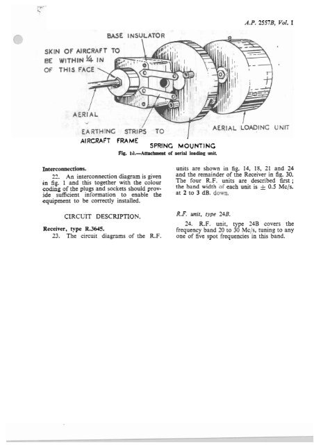
A.P. 2557B, Vol. I<br />
AIRCRAFT<br />
FRAME<br />
SPRING MOUNTING<br />
Fig. 10.-Attachment of aerial loading unit.<br />
I<br />
Interconnections. units are shown in fig. 14, 18, 21 and 24<br />
22. An interconnection diagram is given and the remainder of the Receiver in fig. 30.<br />
in fig. 1 and this together with the colour The four R.F. units are described fht ;<br />
coding of the plugs and sockets should prov- the band width each unit is zk Os5 Mc/s.<br />
ide sufficient information to enable the at to dBequipment<br />
to be correctly installed.<br />
CIRCUIT DESCRIPTION. R.F. unit, type 24B.<br />
24. R.F. unit, type 24B covers the<br />
Receiver, type R.3f345.<br />
frequency band 20 to 30 Mc/s, tuning to any<br />
23. The circuit diagrams of the R.F. one of five spot frequencies in this band.


