2115_ Gee_MkII_Tropical.pdf - VMARSmanuals
2115_ Gee_MkII_Tropical.pdf - VMARSmanuals
2115_ Gee_MkII_Tropical.pdf - VMARSmanuals
Create successful ePaper yourself
Turn your PDF publications into a flip-book with our unique Google optimized e-Paper software.
f--<br />
R.F. unit, typc 26B.<br />
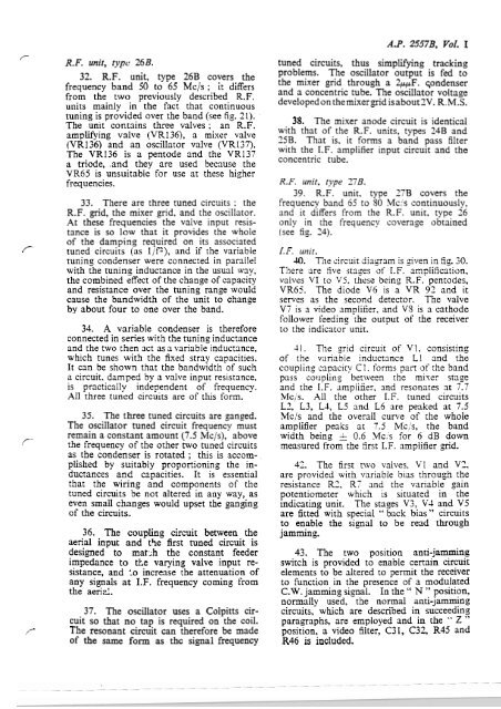
32. R.F. unit, type 26B covers the<br />
frequency band 50 to 65 Mc/s ; it differs<br />
from the two previously described R.F.<br />
units mainly in the fact that continuous<br />
tuning is provided over the band (see fig. 21). .<br />
The unit contains three valves ; an R.F.<br />
amplifying valve (VR136), a mixer valve<br />
(VR136) and an oscillator valve (VR137).<br />
The VR136 is a pentode and the VR137<br />
a triode, .and they are used because the<br />
VR65 is unsuitable for use at these higher<br />
frequencies.<br />
33. There are three tuned circuits : the<br />
R.F. grid, the mixer grid, and the oscillator.<br />
At these frequencies the valve input resistance<br />
is so low that it provides the whole<br />
of the damping required on its associated<br />
tuned circuits (as lip), and if the variable<br />
tuning condenser were connected in parallel<br />
with the tuning inductance in the usual way,<br />
the combined effect of the change of capacity<br />
and resistance over the tuning range would<br />
cause the bandwidth of the unit to change<br />
by about four to one over the band.<br />
34. A variable condenser is therefore<br />
connected in series with the tuning inductance<br />
and the two then act as a variable inductance,<br />
which tunes with the fixed stray capacities.<br />
It can be shown that the bandwidth of such<br />
a circuit. damped by a valve input resistance,<br />
is practically independent of frequency.<br />
All three tuned circuits are of this form.<br />
35. The three tuned circuits are ganged.<br />
The oscillator tuned circuit frequency must<br />
remain a constant amount (7.5 klc/s), above<br />
r‘ the frequency of the other two tuned circuits<br />
as the condenser is rotated ; this is accom- .<br />
plished by suitably proportioning the inductances<br />
and capacities. It is essential<br />
that the wiring and components of the<br />
tuned circuits be not altered in any way, as<br />
even small changes would upset the ganging<br />
of the circuits.<br />
36. The coupling circuit between the<br />
aerial input and t'le first tuned circuit is<br />
designed to mat;h the constant feeder<br />
impedance to the varying valve input resistance,<br />
and to increase the attenuation of<br />
any signals at I.F. frequency coming from<br />
the aerid.<br />
37. The oscillator uses a Colpitts circuit<br />
so that no tap is required on the coil.<br />
r The resonant circuit can therefore be made<br />
of the same form as thc signal frequency<br />
A.P. 25578, Vol. I<br />
tuned circuits, thus simplifying tracking<br />
problems. The oscillator output is fed to<br />
the mixer grid through a 2ppF. qondenser<br />
and a concentric tube. The oscillator voltage<br />
developed on the mixer grid isabout 3V. R.M.S.<br />
35. The mixer anode circuit is identical<br />
with that of the R.F. units, types 24B and<br />
25B. That is. it forms a band pass filter<br />
with the I.F. amplifier input circuit and the<br />
concentric tube.<br />
R.F. unit, type 97B.<br />
39. R.F. unit. type 27B covers the<br />
frequency band 65 to SO Mc's continuously,<br />
and it differs from the R.F. unit, type 36<br />
only in the frequency coverage obtained<br />
(see fig. 24).<br />
I. F. unit.<br />
40. The circuit diagram is ziven in fig. 30.<br />
Tltere are five stages of I.F. amplification.<br />
valves VI to VS. these being R.F. pentodes,<br />
VR65. The diode V6 is a VR 99, and it<br />
serves as the second detector. The valve<br />
V7 is a video amplifier, and VS is a cathode<br />
follower feeding the output of the receiver<br />
to the indicator unit.<br />
41. The srid circuit of V1. consisting<br />
of the variable inductance L1 and the<br />
coupling capaci~y C 1. forms part of rhe band<br />
pass coupling between the mixer stage<br />
and the I.F. ampliiier, and resonates at 7.7<br />
Mc/s. All the other I.F. tuned circuits<br />
L2, L3, L1, L5 and L6 are peaked at 7.5<br />
MC~S and the overall curve of the whole<br />
amplifier peaks at 7.5 lvlc,'s, the band<br />
width being & 0.6 Mc/s for 6 dB down<br />
measured from the first I.F. amplifier ,gid.<br />
42. The first two valves. V1 and V3,<br />
are provided with variable bias through the<br />
resistance R2, R7 and the variable gain<br />
potentiometer which is situated in the<br />
indicating unit. The stases V3, V4 and V5<br />
are fitted with special '' back bias " circuits<br />
to enable the signal to be read through<br />
jamming.<br />
43. The two position anti-jamming<br />
switch is provided to enable certain circuit<br />
elements to be altered to permit the receiver<br />
to function in the presence of a modulated<br />
C.W. jamming signal. In the " N " position,<br />
normally used, the normal anti-jamming<br />
circuits, which are described in succeeding<br />
paragraphs, are employed and in the " Z "<br />
position, a video filter, C31, C32, R45 and<br />
R46 is included.


