2115_ Gee_MkII_Tropical.pdf - VMARSmanuals
2115_ Gee_MkII_Tropical.pdf - VMARSmanuals
2115_ Gee_MkII_Tropical.pdf - VMARSmanuals
Create successful ePaper yourself
Turn your PDF publications into a flip-book with our unique Google optimized e-Paper software.
7. With R.F. units, type 24B and 25B<br />
of which a panel view is shown in fig. 2<br />
any one of five preset spot frequencies in<br />
the band may be selected by a switch.<br />
The R.F. units, type 26B and 27B, panel<br />
views of which are shown in fig. 3, may be<br />
continuously tuned over the radio frequency<br />
ranges by a tuning dial. The following<br />
details give the spot frequencies to which<br />
the switch positions on R.F. units, type 24B<br />
and 25B are normally tuned on leaving<br />
the factory :-<br />
Switch RE unit RF. unit<br />
position type 24B type 258<br />
Mc/s<br />
Mc/s<br />
8. The remainder of the receiver accommodates<br />
a five-stage I.F. amplifier, second<br />
detector, video amplifier, and cathode follower<br />
output stage on the main chassis ;<br />
and on a sub-chassis, a power unit which ,<br />
supplies power to the receiver and the<br />
indicator.<br />
TABLE I<br />
S~ores : Dimensions<br />
Unit Ref. . Weight<br />
I j length Width Hcighr<br />
Receiver, type R.3645 .. 10DB:8477 ' 35 lb. ! 18 in. 1 9 in. 8 in.<br />
I<br />
Indicating unit, type 266 10QBi6383 ! 36 ib. 18 in. 9 in. 12 in.<br />
!<br />
Aerial, aircraft, type 379 10B 16026 - - - -<br />
Control panel, type 3 . .; 5U, 1969 20 lb. 1 , 12in. i 12in. ; 12in.<br />
FROM<br />
R.F<br />
UNIT<br />
OUTPUT<br />
TO<br />
l NDICATOR<br />
+ 0<br />
I ST<br />
1.F:<br />
VI<br />
-<br />
r<br />
- CATHODE<br />
'IDE0- FOLLOWER<br />
.<br />
1<br />
2 ~ 0 3 RD.<br />
~ T H<br />
~ T H<br />
- - IF<br />
- If<br />
OET'<br />
IF<br />
V4<br />
v6<br />
Va<br />
V2<br />
-<br />
V3<br />
v5<br />
.<br />
N EC<br />
KI<br />
H .T.<br />
RECTIFIER<br />
POWER<br />
INPUT<br />
VOLTAGE<br />
STABlLlSER<br />
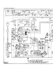
Fig. 5.-Block<br />
schematic diagram of nceivw.


