

2115_ Gee_MkII_Tropical.pdf - VMARSmanuals
2115_ Gee_MkII_Tropical.pdf - VMARSmanuals
2115_ Gee_MkII_Tropical.pdf - VMARSmanuals

You also want an ePaper? Increase the reach of your titles
YUMPU automatically turns print PDFs into web optimized ePapers that Google loves.
r<br />
9. The following controls, sockets, and<br />
plugs are provided on the front panel<br />
of the receiver ;<br />
(i) Pye plug coloured green. The aerial<br />
input plug located on the R.F. unit.<br />
(ii) Pye plug coloured blue. The receiver<br />
output plug, whlch is connected<br />
externally to an input plug. on the<br />
indicating Unit.<br />
(iii) Tuning control. This is located on<br />
the R.F. unit. On R.F. units types,<br />
24B and 25B it consists of a fiveposition<br />
selector switch, and on R.F.<br />
units, type 26B and 27B a tuning<br />
dial with an illuminated scale is<br />
provided. A small knob at the<br />
bottom left-hand corner of the front<br />
panel of R.F. units. type 26B and<br />
27B is used for trimming the aerial<br />
input circuit.<br />
(iv) Anti-jamming s~vitcl~. This is a 2-<br />
position selector switch, with<br />
positions marked " N " and " Z ":-<br />
(a) " N " is the normal position<br />
of the switch and is used when<br />
no jamming is experienced.<br />
(b) " Z " is selected when jamming<br />
is experienced.<br />
(v). 4pin Wplug. This plug is connected<br />
externally to the aircraft alternator,<br />
and pins 1 and 2 provide the SOv.<br />
1500 c/s (nominal) supply to the<br />
I<br />
GAL. PIPS 1SK.dS AN0 3K. C/S<br />
A.P. 2557B, Vol. I<br />
power unit in the receiver. Pins 3<br />
and 4 are not used. .<br />
(vi) 6-pin Wplug. This plug is connected<br />
externally to the indicating unit and,<br />
except for pin 3, provides power<br />
for this unit. Pin 3 provides variable<br />
. bias to the receiver from the receiver<br />
gain control on the indicating unit.<br />
10. Further information on the receiver<br />
and a circuit description are provided in<br />
para. 23 to 54. Fig. 5 shows a block schematic<br />
diagram, fig. 14, 18, 21, 24 and 30<br />
circuit diagrams and fig. 11-13, 15-17,<br />
19-20, 22-23 and 27-28 annotated pictorial<br />
views of the interior of the receiver.<br />
The operation of the anti-jamming circuit is<br />
illustrated in fig. 29.<br />
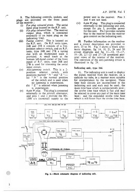
Indicating unit, type 266.<br />
11. The indicating unit is used to display<br />
the pulses received from the receiver, on a<br />
cathode ray tube, in a manner most suitable<br />
for interpretation by the navigator. Three<br />
time base circuits are incorporated in the<br />
indicating unit and each may be used; the<br />
main time base which is comparatively slow ;<br />
the strobe time base which is fast and may<br />
be selected to cover any part of the main time<br />
base ; and the expanded strobe time base<br />
which is still faster than the strobe time base.<br />
M.T. B<br />
SUPPRESSION OF FLYBACK<br />
Y PLATE<br />
SfROBE<br />
INVERTER PULSE. =EN. -,<br />
Y.V3<br />
-<br />
AND V ~ I "I i "8 mo"9<br />
Fig. 6.-Block<br />
schematic diagram of indicating unit.


