Mar - Rcsoaring.com
Mar - Rcsoaring.com
Mar - Rcsoaring.com

You also want an ePaper? Increase the reach of your titles
YUMPU automatically turns print PDFs into web optimized ePapers that Google loves.
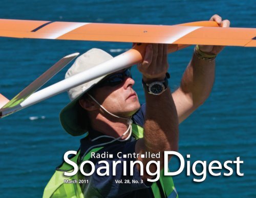
SoaringDigest<br />
Radi C ntr lled<br />
<strong>Mar</strong>ch 2011 Vol. 28, No. 3
CONTENTS<br />
<strong>Mar</strong>ch 2011<br />
Vol. 28, No. 3<br />
3 RC Soaring Digest Editorial<br />
Two Oceans Slope Soarers<br />
4 Aerobatic Event 2011<br />
Cape Town, South Africa, event coverage by Kevin Farr<br />
with photos by Shane Swartz.<br />
The 2-Point-4 Chronicles<br />
20 The personal experiences of the Coyote<br />
Mike Lee relates his history with 2.4 GHz radio systems<br />
in a variety of RC sailplanes.<br />
53 Presumptions vs. Black Box<br />
How 2.4 GHz radio systems and an inexpensive addon<br />
can be used to gather information for post-incident<br />
evaluations. By Sherman Knight<br />
64 Homebrew Thermal Sensor<br />
An electronics project by Pete Carr.<br />
Front cover: Malcolm Riley checks flight surfaces prelaunch.<br />
Photo taken during the Two Oceans Slope Soarers<br />
Aerobatic Event 2011, Cape Town, South Africa. Full event<br />
coverage starts on page 4 of this issue. Photo by Shane Swartz<br />
Nikon D90, ISO 400, 1/250 sec., f16, 150mm<br />
FAI Sporting Code<br />
Section 4 Aeromodeling<br />
Radio Control Soaring 69<br />
Updated regulations for F3B, F3F, F3J, F3K, F3H, and<br />
F3Q, plus rules for World Cup events.<br />
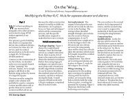
Notes concerning A Design Philosophy 90<br />
Recent items of interest concerning Bruce Abell's article<br />
in the February issue.<br />
Flaps for Swept Wings 91<br />
Norman Masters uses a minimum of math and several<br />
diagrams to explore appropriate flap size and location to<br />
minimize pitching during deflection.<br />
Civil Air Patrol uses gliders in its cadet<br />
program to teach fundamentals of flight 96<br />
By Maj. Steven Solomon CAP<br />
Back Cover: A Supra and its JR 12X DSM transmitter<br />
est in the tall grass under the summer sun at Camp<br />
Korey, Carnation, Washington. Photo by Bill Kuhlman<br />
Konica Minolta Maxxum 7D, ISO 100, 1/300 sec., f8, 35mm<br />
2 R/C Soaring Digest
R/C Soaring Digest<br />
Managing Editors, Publishers<br />
Contributors<br />
B 2 Kuhlman<br />
Pete Carr<br />
Fédération Aéronautique Internationale<br />
Kevin Farr<br />
Sherman Knight<br />
Mike Lee<br />
Norman Masters<br />
Maj. Steven Solomon CAP<br />
Photographers CAP California Wing Squadron 41<br />
Pete Carr<br />
Mike Lee<br />
Shane Swartz<br />
Contact<br />
rcsdigest@centurytel.net<br />
Web: http://www.rcsoaringdigest.<strong>com</strong><br />
Yahoo! group: RCSoaringDigest<br />
AIM screen name: RCSDigest<br />
Microsoft Messenger: rcsdigest<br />
R/C Soaring Digest (RCSD) is a reader-written monthly publication<br />
for the R/C sailplane enthusiast and has been published since January<br />
1984. It is dedicated to sharing technical and educational information.<br />
All material contributed must be original and not infringe upon the<br />
copyrights of others. It is the policy of RCSD to provide accurate<br />
information. Please let us know of any error that significantly affects<br />
the meaning of a story. Because we encourage new ideas, the content<br />
of each article is the opinion of the author and may not necessarily<br />
reflect those of RCSD. We encourage anyone who wishes to obtain<br />
additional information to contact the author.<br />
———<br />
Copyright © 2011 R/C Soaring Digest<br />
Published by B2Streamlines <br />
P.O. Box 975, Olalla WA 98359<br />
All rights reserved<br />
———<br />
RC Soaring Digest is published using Adobe InDesign CS5<br />
In the Air<br />
Our sincere thanks to everyone who contributed<br />
materials to this <strong>Mar</strong>ch 2011 issue of RC Soaring Digest.<br />
The topics this month cover a range of subjects —<br />
aerodynamics and electronics, FAI regulations for F3<br />
classes, full size and RC soaring within the Civil Air<br />
Patrol, event coverage, and 2.4 GHz radio systems.<br />
We've seen a number of technologies arrive on the<br />
scene during the more than 50 years we've been<br />
involved in RC soaring. New construction materials, new<br />
adhesives, and new electronics. We've gone through<br />
balsa, spruce, fiberglass, Kevlar, boron and carbon;<br />
acetone-based glues, PVA, cyanoacrylate and various<br />
forms of epoxy; tubes, transistors and SMT, along with<br />
solenoid escapements, coreless servo motors... The list<br />
goes on and on. While some of these technologies have<br />
now entirely disappeared from the RC soaring scene,<br />
the reason has always been that new technologies have<br />
taken their place.<br />
The advent of 2.4 GHz radio systems has already<br />
made a huge impact on the RC soaring scene and the<br />
technology is being continuously improved. There are<br />
a number of very positive aspects to using 2.4 GHz<br />
systems rather than continuing to fly on the 72 MHz<br />
band, and the benefits to be derived and the low cost<br />
of transition are well explained within the two relevant<br />
articles in this issue. We are now in the process of<br />
switching over to 2.4 GHz as rapidly as we can!<br />
Time to build another sailplane!<br />
<strong>Mar</strong>ch 2011 3
TWO OCEANS SLOPE SOARERS<br />
Text by Kevin Farr, kevin@fvdv.co.za<br />
Photos by Shane Swartz<br />
AerobaticEvent2011<br />
4 R/C Soaring Digest
Hosted in Cape Town, South Africa,<br />
for the third year in a row on the last<br />
weekend of January, the Two Oceans<br />
Slope Soarers Aerobatics Event rolled<br />
out for the 2011 <strong>com</strong>petition.<br />
As blessed as we are in this wonderful<br />
slope soaring part of the world, one<br />
could not have hoped for better<br />
weather as Mother Nature rolled out<br />
the red carpet and delivered a Saturday<br />
<strong>com</strong>petition session of note up at Red<br />
Hill.<br />
Starting off a little bit on the light side<br />
there were a few worried organisers but<br />
true to form, as the 10 AM start time<br />
approached the South Easter stirred,<br />
gathered its wits and blew through the<br />
most beautifully consistent South Easter<br />
that we have had this season. Ranging<br />
from the early morning 25 km per hour,<br />
right through to the 40 km per hour wind<br />
by the evening, the lift remained perfect,<br />
stable and offered the gathered sloping<br />
clan the best available opportunity to<br />
show off their <strong>com</strong>petition skills.<br />
First round kicked off at 10AM sharp,<br />
and with ready boxes in place there were<br />
always two pilots airborne and two at<br />
the ready, and in said box, keeping the<br />
flow of air traffic at an optimum under<br />
the steady direction of Uncle Bill Dewey,<br />
Contest Director for the event.<br />
Competition and nerves go hand in<br />
hand and there were more than a few<br />
nerves jangling away at the <strong>com</strong>petitors<br />
as they stepped up to the line. The more<br />
seasoned <strong>com</strong>petitors, the likes of <strong>Mar</strong>c<br />
Wolfe and Louis Genade, handled their<br />
nerves the best and so showed what<br />
regular <strong>com</strong>petition flying can do for<br />
ones performance in front of the four<br />
excellent judges who stared out into<br />
the blue yonder. Due to a lack of calling<br />
practice, some scored less than they<br />
could have and showed the need for a<br />
caller/pilot team to be really established,<br />
well practised and versed with each<br />
other.<br />
In the end, we were able to fly the full 15<br />
pilots through round one, round two and<br />
the half pipe routine all in one day. Quite<br />
a feat for the organisers. A few injuries<br />
to gliders occurred, Cape landings are<br />
not as easy as they first appear with the<br />
fynbos only too happy to chew up any<br />
erring gliders. But true to slope fellows,<br />
never is not an attitude well applied.<br />
Notables for the day were Dave Greer<br />
literally shaking off the Toksix vertical<br />
stabiliser mid-flight, requiring the<br />
generous application of cyno, Russel<br />
Conradt damaging his aero on landing,<br />
taping with fibre tape and continuing<br />
to <strong>com</strong>pete, and the best being Bobby<br />
Purnell who snapped his Vector 111<br />
boom, called his wife to race out to Red<br />
Hill and bring his repair kit. He repaired<br />
the boom in the car-park and then flew<br />
the second round with said repair while<br />
the epoxy hardened in flight. It’s really<br />
difficult to beat that sort of spirit.<br />
Sunday dawned promising but failed<br />
to deliver as a southerly wind blew and<br />
the one slope we cannot cater for at this<br />
stage is a south slope. So after breakfast,<br />
plenty on toungue wagging, story<br />
swapping and photographic sessions the<br />
entire crew headed for Fisherman’s and<br />
the awards presentation.<br />
The Durban crew of Dave Greer, Russel<br />
Conradt, <strong>Mar</strong>k Phillips and Johan de<br />
Lange spent the weekend grinning like<br />
Cheshire cats, and once more we have to<br />
thank them for making the journey to the<br />
Cape and adding their special characters<br />
to the mix.<br />
A big thanks to the judges, Andrew<br />
Anderson, Johnny Calafato, and Claude<br />
and Kurt, the expert father and son team,<br />
for toiling tirelessly though the heat of the<br />
day.<br />
Thanks to all the <strong>com</strong>petitors who<br />
attended the event and through their<br />
friendly, humorous and indomitable<br />
spirits made it one more an event to<br />
remember.<br />
A huge thanks to TOSS Chairman, Jeff<br />
Steffen and the TOSS <strong>com</strong>mittee who<br />
prepared, sweated blood and planned for<br />
the best and as such received the best.<br />
Well done lads, one and all.<br />
And finally a grateful thanks to all the<br />
sponsors who came to the party with<br />
excellent prizes, from the last position<br />
to the first, every participant receiving a<br />
prize.<br />
Just plain magic.<br />
<strong>Mar</strong>ch 2011 5
<strong>Mar</strong>c Wolfe’s wining glider going through the paces.<br />
6 R/C Soaring Digest
Gus Thomas preps the Voltij for his round.<br />
Johan de Lange, all the way from<br />
Pietermaritzburg, and smiling all weekend.<br />
Wiggle waggle, OK so that works!<br />
<strong>Mar</strong>ch 2011 7
Damian Hinrichsen gives the Vector a good old heave.<br />
8 R/C Soaring Digest
Russell Conradt preps for the round.<br />
No! It’s not a hug! It’s like that way first<br />
and then that way second...<br />
Damian Hinrichsen and Kevin Farr setting up for round.<br />
<strong>Mar</strong>ch 2011 9
Right: <strong>Mar</strong>c gets ready to set the Aldij free.<br />
Below: Bobby Purnell and Louis Genade<br />
Above: Kevin Farr’s Vector 111 makes the drop into the landing zone.<br />
10 R/C Soaring Digest
Steve Meusel gets Jeff Steffen’s<br />
Mini Dragon into the air.<br />
<strong>Mar</strong>ch 2011 11
Left: Flight line over the bay.<br />
Below left: Judges busy at<br />
work – a huge thank you to<br />
them all.<br />
Below: Pilots and callers<br />
all concentrating with great<br />
intensity.<br />
12 R/C Soaring Digest
Steve’s lightning quick built (2 weeks) aero flew into third position.<br />
<strong>Mar</strong>ch 2011 13
This page:<br />
Bobby Purnell’s<br />
Vector 111<br />
makes its way<br />
to the launch<br />
zone in the<br />
hands of Bruce<br />
Southwood.<br />
Opposite page:<br />
The Vector 111<br />
going through its<br />
routine.<br />
14 R/C Soaring Digest
<strong>Mar</strong>ch 2011 15
A beautiful spot for aerobatic flying.<br />
Opposite page: Steve Meusel’s glider half way through a roll.<br />
16 R/C Soaring Digest
<strong>Mar</strong>ch 2011 17
Altogether now ladies — what an awesome bunch of <strong>com</strong>petitors!<br />
18 R/C Soaring Digest
Two Oceans Slope Soarers Aerobatic Event 2011<br />
Top 3 at the end of the day. Steve, <strong>Mar</strong>c and Loius<br />
AMT<br />
<br />
CAPE SAILPLANES<br />
<br />
HOBBY WAREHOUSE<br />
<br />
INERTMET AFRICA<br />
SPONSORS<br />
MICTON HOBBIES<br />
<br />
SOUTHERN HOBBIES<br />
<br />
RUSSELL CONRADT<br />
DAVE GREER AND FRAGRAM<br />
KEVIN FARR AND IRIS VAN DER VLIST<br />
<strong>Mar</strong>ch 2011 19
The 2-Point-4 Chronicles<br />
The personal experiences of the Coyote<br />
Mike Lee, mlee8249@msn.<strong>com</strong><br />
This is the experiences of a pilot gone<br />
south. 2.4 Ghz is a new frontier for many<br />
people, with a lot of talk on theory,<br />
application and horror that I just had to<br />
find out if they were true or false. Most of<br />
what we did here in the Chronicles goes<br />
against what is re<strong>com</strong>mended by the<br />
radio manufacturers and is not endorsed<br />
nor re<strong>com</strong>mended by them. This is a<br />
lot of experimentation, daring attempt,<br />
and in some cases, just do it and see<br />
what happens. Your own mileage may<br />
vary, but we do re<strong>com</strong>mend that you<br />
follow the instructions given by the radio<br />
manufacturers for best results.<br />
Wel<strong>com</strong>e to the 2-Point-4 Chronicles.<br />
Let’s get right down to the reason why<br />
the Chronicles is being written; we want<br />
to see what we can get away with on 2.4<br />
Ghz! This is new territory for most pilots.<br />
This is strange stuff with short antennas,<br />
no frequency flags, no screaming out<br />
on the field what channel you’re on, no<br />
more sneaking the Tx in the pit and doing<br />
a real quick radio check without the<br />
pin, and no more shoot downs because<br />
someone else sneaked a Tx into the pits.<br />
It gets even stranger with some radios<br />
that perform frequency hopping, others<br />
that do frequency scanning and locking,<br />
and at least one other that (in my opinion)<br />
doesn’t even work! But here we have<br />
had for the past 20 years a fairly stable<br />
RF environment in the 72-Mhz band, that<br />
got narrow banded in 1991 for the better,<br />
and all that stability got uprooted with<br />
2.4. So, let’s get right down to it; let’s<br />
jump into experiments we have done in<br />
radio control that in some cases, people<br />
say should not work at all, but did, and in<br />
other cases should work, but didn’t.<br />
First, let’s get some acronyms down.<br />
That way you won’t be looking around for<br />
the definitions:<br />
• Tx – Transmitter<br />
• Rx – Receiver<br />
• Ghz – Gigahertz. This is 1,000,000,000<br />
cycles per second, RF frequency.<br />
• Mhz – Megahertz. This one million<br />
cycles per second, RF frequency.<br />
• RF – Radio frequency. (Or, could also<br />
mean Rat Fink, but we won’t go there)<br />
• CF – Carbon fiber<br />
• G-10: A type of fiberglass material.<br />
Typically used in circuit boards for<br />
electronics.<br />
Now, most of the experimentation<br />
done here is done in a rather unusual<br />
environment of the “carbon” world. In<br />
the most recent 10-years, the use of<br />
carbon fiber within the construction<br />
of our models has greatly expanded.<br />
It is extremely light and strong when<br />
properly embedded into a medium, such<br />
20 R/C Soaring Digest
as epoxy resin. We use it extensively in<br />
<strong>com</strong>petition models of all types to gain<br />
structural strength and rigidity, plus it’s<br />
just cool! Understand, first, how this stuff<br />
is made. To make a very long story very<br />
short, you make this stuff by burning<br />
rayon and poly type fabrics down to<br />
nothing but the carbon that it is based<br />
on. It takes tremendous heat and some<br />
high pressure for this to happen, but<br />
in short that’s what they do. Carbon in<br />
itself is an atomically light material, but<br />
when <strong>com</strong>pounded with other elements,<br />
it be<strong>com</strong>es not only very dense but<br />
conductive to electricity. The conductive<br />
stuff is more or less what we end up<br />
using in our models. Because it is dense,<br />
and conductive, it does two things to<br />
the RF signals of our radio systems.<br />
The first is that it will block the signals<br />
from penetrating the material. It not only<br />
deflects the signal to a degree, but it also<br />
absorbs the signal using the electrical<br />
conductive properties it possesses. That<br />
second property of carbon fiber is one<br />
of the reasons it is used extensively in<br />
“stealth” aircraft. So, that being the case,<br />
you can now understand why it’s not<br />
good to place a carbon fiber structure<br />
between the radio Tx and the Rx. That<br />
signal just ain’t going to get through<br />
<strong>com</strong>pletely intact.<br />
Okay, so we have that fact of life down,<br />
and if you need to prove this to yourself,<br />
just try it out and you’ll see. It’s an<br />
easy experiment. Just remember that<br />
a ground range check proves nothing<br />
when it <strong>com</strong>es to carbon fiber. This leads<br />
us to our first experiment, only this one<br />
was originally done in 72-Mhz form.<br />
The situation is that we want to keep<br />
from having antenna wire hanging out<br />
of our wonderful, aerodynamically clean<br />
sailplanes, because the wire produces<br />
drag... and it looks ugly! At this time,<br />
most of the <strong>com</strong>petition planes were<br />
using a significant amount of carbon fiber<br />
(CF) in the construction of the fuselage to<br />
keep them light and also to give them the<br />
strength to withstand the typical “dork”<br />
landing.<br />
This is an Onyx 3.5 meter model and although the photo is small, you can clearly see<br />
the black, carbon fiber tail boom. In reality, the 72-Mhz antenna is wound around the<br />
tail boom on the outside of the boom. In this case, it did work, but the antenna suffered<br />
damage almost every time the plane landed as the fuselage scraped along the ground.<br />
<strong>Mar</strong>ch 2011 21
See that little wire on the tail boom<br />
72-Mhz wire!<br />
Some pilots found out the hard way<br />
that placing the 39-inch long antenna of<br />
their 72-Mhz Rx down the tail boom was<br />
death on wings. They would range check<br />
in some cases, but that was about it.<br />
So, I set about figuring out how to get by<br />
this.<br />
My first thing was to run the antenna<br />
wire along the boom on the outside. For<br />
many cases, this worked, but it really<br />
depended on just how much carbon<br />
was in that tailboom. On mine, it was<br />
pure carbon painted over. Remember<br />
we talked about how carbon absorbs<br />
RF Well, that was almost catastrophic<br />
as we range checked fine, but in the air,<br />
it was lock-out city! The carbon boom<br />
was absorbing the RF signal and that left<br />
nothing for the Rx. Not to be discouraged<br />
and being basically dumb, I then ran<br />
the antenna inside and had about<br />
10-inches hanging out in the wind from<br />
about halfway down the boom length.<br />
That worked! Now, by theory, the CF<br />
tailboom should have shielded the length<br />
of antenna inside the boom, meaning<br />
the only length of antenna that could see<br />
the RF signal was the 10-inches hanging<br />
out. But, this should seriously de-tune<br />
the antenna, making it in-effective... in<br />
theory! In application, it didn’t. So, we<br />
took it a bit further. Why let 10-inches of<br />
wire hang out halfway down the fuselage<br />
when it would be better to have it exit<br />
out the very tip of the tail where it would<br />
be out of the way and better looking<br />
Well, the run out the tail was longer than<br />
the entire length of the antenna... Now<br />
what If I lengthen the antenna, that<br />
22 R/C Soaring Digest
should result in an out of tune antenna<br />
and failure of the Rx... right To a degree,<br />
yes. So, I added a wad of wire to the end<br />
of the antenna and proceeded to run it<br />
out the tail. There we are with 14- inches<br />
of wire hanging out and a range check to<br />
see what happens.<br />
Now, we know that the JR system wants<br />
to range check to 75-feet for satisfactory<br />
results. We did that with the Rx out in<br />
the open and a normal length antenna.<br />
We checked again after adding the<br />
wire to the antenna. That was kind of<br />
miserable on results, but we trudged on.<br />
We installed the Rx into the plane and<br />
did the range check. We got 45 feet. I<br />
then began clipping the wire in one-inch<br />
increments. When we hit 12-inches, the<br />
range check went to 52-feet. Hmmmm,<br />
me thinks we are on to something! As we<br />
continued to clip one inch at a time, the<br />
range check got better until we got to 7<br />
inches. At 8 inches out, we had achieved<br />
some 84 feet of range check. Amazing!<br />
This was better than the stock length<br />
antenna outside of the plane! When<br />
we clipped the antenna to 7 inches,<br />
the range check reduced to 80 feet.<br />
That was enough for us, so we put the<br />
antenna back to 8-inches out and left it.<br />
The plane performed perfectly for over a<br />
year. Not only that, but every other plane<br />
I had with similar carbon construction<br />
was also treated this way with no<br />
problem.<br />
Knowing all that, we move to 2.4 Ghz.<br />
But before we get into that, let’s look at<br />
what people were tossing around on the<br />
Internet and other places:<br />
• You can’t let anything get between the<br />
Tx and the plane because it is strictly<br />
line-ofsight.<br />
• You can’t fly anywhere around<br />
populated areas because the garage<br />
door openers and cordless phones might<br />
get you... they’re on 2.4 Ghz.<br />
• They have limited range because they<br />
don’t have the same signal strength.<br />
• I’ll let the other guys crash, burn<br />
and learn before I switch because I<br />
don’t like being the guinea pig for new<br />
technologies. And it will get people off of<br />
my beloved 72-Mhz frequency!<br />
So, that being said, let’s look at what<br />
the real world says in 2.4 technology.<br />
Letting something get between you<br />
and the plane is not going to cost you<br />
a plane. I heard it said that a tree can<br />
block the signal. Not so, as a tree is quite<br />
transparent to 2.4Ghz. Now, you might<br />
certainly lose the plane because you<br />
can’t see it anymore, but not because<br />
the tree blocked the signal. If this were<br />
true, then we could not use 2.4 Ghz<br />
inside a wood plane. My experiment<br />
in this case was to deliberately fly my<br />
planes behind the most <strong>com</strong>monly talked<br />
about objects... trees and people. At<br />
my home field, we have tall eucalyptus<br />
trees and I flew a dozen missions<br />
where I flew behind the trees at varying<br />
distances. There were a number of<br />
nervous moments as I lost eyesight of<br />
the planes for up to 10-seconds. But in<br />
each case, the plane came out the other<br />
side smiling away. (Except once when<br />
the plane found the tree!) This was then<br />
confirmed by reading the Spektrum Flight<br />
Log device, which recorded no “holds”<br />
on the signal. Then, carrying this even<br />
further, I attended a very large contest<br />
event where a couple dozen planes were<br />
in the air at the same time. I deliberately<br />
stood behind people to see if I could get<br />
a persons’ body to block the signal. And<br />
I mean I stood right behind them, close<br />
enough to touch them. No loss. So, that<br />
myth is busted. The only truth here is the<br />
line-of-sight, but only to the point of what<br />
you, the pilot, cannot see, you cannot<br />
control. Busted!<br />
Flying in populated areas due to other<br />
users of 2.4 frequencies... interesting<br />
thoughts and valid for consideration.<br />
But you have to remember how these<br />
systems work. The two most popular<br />
systems in use either switch frequencies<br />
at high speed, known as frequency<br />
hopping, or they lock on to two<br />
frequencies within the band that are not<br />
being used. Both are effective schemes<br />
and they work. As for garage door<br />
openers messing with you, you have to<br />
consider that a door opener has nothing<br />
even close to the power output that we<br />
<strong>Mar</strong>ch 2011 23
do. You might be able to open the garage<br />
from several houses down the block,<br />
but not from a half-mile away, even on a<br />
clear day with nothing in the way. These<br />
systems, designed for consumer use,<br />
have less than 100-mw of output power,<br />
while we have far greater power available.<br />
Also, they are intermittent at best, where<br />
we are constantly transmitting.<br />
2.4 has limited range... well, yeah...no<br />
kidding! The FCC regulates that and<br />
does that to darn near everyone save for<br />
maybe the Military. But as far as practical<br />
range of 2.4 for modeling use, we have<br />
more than plenty of range. The models<br />
that typically have range problems are<br />
those that fly the farthest away from<br />
the pilot... sailplanes! It’s no secret that<br />
<strong>com</strong>petition sailplane pilots fly up to a<br />
mile away on any given flight in search of<br />
thermals. Most sport pilots will be hard<br />
pressed to fly a quarter mile away on a<br />
consistent basis. Let’s just say that the<br />
range of 2.4 Ghz is more than what the<br />
human eye can see. If you can’t see it,<br />
you can’t control it, and the plane will<br />
return to earth... somewhere.<br />
Lastly, letting the other guys crash and<br />
burn for learning is an okay approach,<br />
but let’s face it... the learning curve is<br />
way ahead of you. 2.4 for airborne use<br />
may be seemingly new, but it really is not.<br />
Ground radio sets using 2.4 Ghz have<br />
been in use for at least 3 years before the<br />
frequency was adapted to airborne use.<br />
That was a masterful approach because<br />
the worst that could happen to an R/C<br />
car was that it might crash, and we all<br />
know these cars can take serious abuse<br />
before they break, unlike planes. Once<br />
they were <strong>com</strong>petition proven, which was<br />
normally the worst case situation, the<br />
manufacturers went into the air. There<br />
was a lot of testing and design work put<br />
into the airborne systems before they<br />
dared to release any of this stuff to the<br />
general public, and of course, this is also<br />
why we have the 2-point-4 Chronicles.<br />
So, rest assured that all the crash and<br />
burning with learning is far behind us. 2.4<br />
is here to stay and is a solid system for<br />
airborne use.<br />
Now, I admit that I was on that same<br />
fence post of waiting to see what might<br />
happen in 2.4 when it came out. Here I<br />
am with a hanger full of models, ranging<br />
from big 50cc gassers to tiny Speed<br />
Electric pylon racers and a bunch<br />
of sailplanes. If I make this move to<br />
2.4, then I am looking at a major reinvestment<br />
of equipment and credit card<br />
debt. But, not be to the last guy on the<br />
block to change, I jump in with both feet<br />
only 2-weeks prior to the largest sailplane<br />
event in the country, the Visalia Fall<br />
Soaring Festival. Over 300 pilots from<br />
all over are going to be there, and I may<br />
be one of the first to fly in this hostile RF<br />
environment with 2.4. Should be good!<br />
My plane of choice is my beloved<br />
Shadow, a 3.7 meter span bird that is all<br />
carbon in the fuselage and 50-percent<br />
carbon in the wings. Well, the first thing I<br />
like to do is to keep things simple. Being<br />
CF blocks and absorbs RF stuff, I knew<br />
we had to get the antennas outside the<br />
fuselage. That was easy, as I simply<br />
drilled small holes for the short antennas<br />
to poke out of the fuselage. I lovingly<br />
called these the planes’ whiskers. Not<br />
exactly clean and aerodynamic, but it<br />
was not as much drag on the airframe as<br />
a length of antenna wire from a 72-Mhz<br />
system.<br />
I placed a JR R921 Rx inside with a<br />
single satellite Rx helping out. I then<br />
figure out that in order to get maximum<br />
“visual” angle from the transmitted<br />
signal to the antennas, we had to place<br />
the antennas such that no matter what<br />
angle the plane is at relative to the<br />
transmitter, one of the antennas can<br />
see the transmitter. So, I placed them<br />
in an “around-the-clock” arrangement<br />
at 2:00 o’clock, 4, 8 and 12:00 o’clock<br />
locations on the fuselage. Guess what<br />
To this day, the Shadow retains that<br />
exact set-up without a glitch. It took me<br />
5 months to record my first “hold” on the<br />
Spektrum Flight Log device. But, it just<br />
so happened that the narrow fuselage of<br />
the Shadow allowed me to use the stock<br />
antenna length.<br />
24 R/C Soaring Digest
My plane of choice is my beloved<br />
Shadow, a 3.7 meter span bird that is all<br />
carbon in the fuselage and 50-percent<br />
carbon in the wings.<br />
I simply drilled small holes for the short<br />
antennas to poke out of the fuselage. I<br />
placed them in an “around-the-clock”<br />
arrangement at 2:00 o’clock, 4, 8 and<br />
12:00 o’clock locations on the fuselage.<br />
To this day, the Shadow retains that exact<br />
set-up without a glitch.<br />
Note that in our photo the whiskers are<br />
up against the fuselage, which we found<br />
out is a no-no!<br />
Part Two<br />
Shielding and Wire Length<br />
We saw in part one that we could get a<br />
simple 2.4 installation into an all carbon<br />
model by letting the short 2.4 antennas<br />
hang out like whiskers on a cat. Maybe<br />
not aesthetically pleasing, but it is simple<br />
and it works. But, we wanted to add<br />
some other things to the model and<br />
needed a bit more room. Now, we have<br />
already drilled a few holes in the fuselage<br />
to allow the antenna wires to poke on<br />
out, and that being done, didn’t care to<br />
drill anymore holes in the plane. With<br />
what we wanted to install into the plane,<br />
it would be necessary to move the Rx<br />
back deeper into the fuselage. So, we<br />
either drill new holes, or we make them<br />
antenna wires longer. I opted for longer<br />
wires.<br />
The theory here is that the exposed<br />
wire is what receives the signal, and we<br />
already know that carbon fiber (CF) not<br />
only blocks the signal, but also absorbs<br />
the signal. So, in essence, the CF<br />
fuselage is “shielding” the antenna wire.<br />
Therefore, it makes sense that if we want<br />
proper reception, we should be able<br />
to run as much wire as we want (within<br />
reason) as long as there is the proper<br />
length of unshielded wire out there to<br />
receive signals at the correct wavelength.<br />
My experiment is now similar to the one<br />
we did with the 72-Mhz radio in that we<br />
should be able to run a longer wire as<br />
<strong>Mar</strong>ch 2011 25
long as we can get some wire outside of<br />
the fuselage<br />
In this case, I did some improvising. To<br />
extend the wire, we clipped the stock<br />
antenna as short as we could dare to<br />
and still have enough wire outside the<br />
receiver case to make a clean, precision<br />
solder joint. 1/8 inch was enough.<br />
I then soldered a length of shielded<br />
coaxial wire to the stub of the antenna<br />
and placed some heat shrink over the<br />
joint. We now have shielding from the<br />
receiver case on out to whatever the tip<br />
will be. I reinstalled the receiver to the<br />
model in its’ new position and then ran<br />
the new antenna wire out the original<br />
holes in the fuselage. With an abundance<br />
In this photo, we<br />
see the coaxial<br />
wire now attached<br />
to the original<br />
antenna wire and<br />
covered with heat<br />
shrink tubing.<br />
This is an AR9000<br />
receiver by<br />
Spektrum Radio.<br />
of wire hanging out the fuselage, we<br />
then removed the shielding from the<br />
wire that was hanging out, leaving only<br />
a single conductor wire. That wire was<br />
then clipped down to the original antenna<br />
wire length of 32mm, and we proceeded<br />
to perform a standard range check...<br />
perfect! It worked, but will it work in the<br />
air Only one way to find out... fly! And<br />
fly we did. Not a problem and the system<br />
worked perfectly.<br />
Now, I know what you electrical people<br />
are thinking; shielded wire has to be<br />
grounded to work properly. Not in this<br />
case! I have now been flying this model<br />
constantly for the past 18 months and<br />
it has yet to miss a beat. What is not<br />
supposed to work is working perfectly.<br />
But let’s look at what reality says. Theory<br />
says that for a shielded wire to work,<br />
it needs to be grounded. But, all we’re<br />
trying to do here is block the signal<br />
from all but the exposed 32mm worth<br />
of exposed wire. 2.4 signals are indeed<br />
easily blocked, but not by things that<br />
are RF transparent in that frequency<br />
range. We have already proven that trees<br />
and wood are transparent as are most<br />
humans. (There may be exceptions out<br />
there... lots of different people around<br />
this earth.) But in the real world, the<br />
simple grid of wire mesh that is used for<br />
shielding on wire is sufficient to block<br />
the signal on the antenna and allow me<br />
to get away with extending the antenna<br />
at will. I’m not saying this is absolutely<br />
correct and that’s the way to go. The<br />
absolutely right way would, in fact, be to<br />
use a grounded shielded wire and then<br />
have the final 32mm of the wire exposed<br />
for the antenna. A great example of this<br />
is the new JR AR500 receiver.<br />
For the curious people out there, you can<br />
take the cover off of the unit and look at<br />
the antenna connection to the PC board.<br />
You will have to carefully peel back the<br />
silicon glue that holds the antenna to the<br />
Rx board. The longer antenna wire is<br />
attached by a micro connector that has<br />
a core contact and outer shield contact,<br />
indicative of a grounding circuit. (Yes,<br />
you just negated the warranty by digging<br />
in there. Don’t blame me for that!)<br />
26 R/C Soaring Digest
This experiment has proven that<br />
simplicity will work and it will perform in<br />
a very RF hostile environment. And as<br />
usual with me, I want to test the extreme.<br />
That brings us to the next experiment;<br />
a hostile RF environment flying in<br />
extremely close quarters to other radios.<br />
To me, the most extreme situation for this<br />
is the International Hand Launch Glider<br />
Competition (IHLGC) held in San Diego,<br />
Ca each year. In this event, some 12 to 15<br />
pilots will fly simultaneously in relatively<br />
close quarters to each other. This is not<br />
too bad, until you consider that your<br />
model will initially launch to about 150-ft<br />
and then must land at least three times<br />
within a typical 10-minute flight time.<br />
The AR500 receiver from<br />
Spektrum Radio has a single<br />
short antenna and a single long<br />
antenna. The long one is made<br />
from shielded coax wire with<br />
only the final 32-mm of the inner<br />
conductor being exposed from<br />
the shielding.<br />
That’s still not too bad. What’s bad is<br />
that these models will routinely be hand<br />
catch landed right after you just flew an<br />
approach that rarely sees you <strong>com</strong>e in<br />
without somebody in the way. Normally,<br />
you have to fly over several other pilots<br />
to get to your landing zone, and for the<br />
most part the other pilots can reach up<br />
and touch you... literally! So, you have<br />
very strong RF signals bombarding your<br />
plane on every launch and every landing,<br />
and the plane is made mostly from CF or<br />
Kevlar .<br />
In the past, it took a very well made<br />
receiver to survive this environment, and<br />
I can’t even begin to list those receivers<br />
that did not handle it. I can tell you that<br />
the list of receivers that could handle it<br />
is short and distinguished. In my book,<br />
I knew of only 3 receivers that I trusted<br />
to work without getting hit, and two of<br />
them are no longer in circulation. In this<br />
situation, we did not have the room to<br />
place a 2.4 Rx with a satellite inside the<br />
plane. It had to be a micro size Rx and<br />
weight is also a big factor. My experiment<br />
took a Spektrum AR7000 without the<br />
casing placed into a Taboo GT DLG<br />
model. This is a top-of-line <strong>com</strong>petition<br />
model that weighs in at only 9.5 oz,<br />
and it costs more than $400.00 for the<br />
airframe alone. Kind of expensive for<br />
experimentation, but you have to prove<br />
the point. The AR7000 was a tight fit,<br />
but it left no room for the satellite Rx.<br />
We placed the satellite under the wing<br />
outside the plane, and this set-up was<br />
highly successful. In fact, we flew this<br />
model in the IHLGC as one of the very<br />
first models so equipped. Not a single<br />
hit on the radio was noted. (No, we didn’t<br />
win, but we did not have a radio problem,<br />
either).<br />
But it was not the optimum setup. Enter<br />
the AR500. The AR500 does not need a<br />
satellite RX, and it has one antenna wire<br />
extended from the factory. That was an<br />
easy install, with the short antenna going<br />
though the fuselage and out the bottom<br />
and the other antenna going through<br />
the fuselage to the wing saddle where it<br />
just sits at the trailing edge of the wing,<br />
outside of the CF fuselage. This setup<br />
<strong>Mar</strong>ch 2011 27
This is a Taboo GT hand launch glider fuselage that is made from all carbon<br />
construction. The receiver is a Spektrum AR500 with one long antenna and one short<br />
one. The short one exits straight down out the bottom of the fuselage while the long<br />
one goes back through the wing saddle and exits just behind the wing.<br />
worked flawlessly and despite the long<br />
wire being hidden by the wing being on<br />
top, the Kevlar construction of the<br />
wing is transparent to the antenna. But<br />
for my flying partner, this was not good<br />
enough. He refused to drill a hole into his<br />
Arrow Pro DLG fuselage.<br />
He took the experiment further.<br />
Using the same AR500 Rx, he simply<br />
extended the short antenna to match the<br />
longer antenna, running it through the<br />
fuselage. Mind you, this was not shielded<br />
wire! Now, both wires are hanging out<br />
behind the wing trailing edge with one<br />
running in shielded coax and the other<br />
just simple wire. The range check did not<br />
go so well. We reviewed the set up and<br />
found that his new long wire was hanging<br />
out about 45 mm from the fuselage,<br />
which is all CF. We then clipped that wire<br />
to be 32 mm long as it hung out of the<br />
fuselage. When we did the next range<br />
check, we were surprised to find out our<br />
range check was better than original! 33<br />
paces is what the Spektrum instructions<br />
re<strong>com</strong>mends for a range check, and we<br />
got 45 paces where our original range<br />
check was only 35 paces.<br />
What did we really do in this case Pretty<br />
simple, actually. The entire fuselage of<br />
the Arrow Pro is solid molded CF... a<br />
perfect shielding for the wire antenna.<br />
By allowing only the final 32 mm to be<br />
exposed outside of the fuselage, the CF<br />
did the work for us and negated the need<br />
for the shielded wire. Is this the absolute<br />
best way to go Not by any stretch of<br />
the imagination, as again, the shielded<br />
and grounded wire is the best and most<br />
correct way. But you have to admit, we<br />
are again getting something to work that<br />
is not supposed to.<br />
• Conversion equipment: How to change<br />
from 72-Mhz to 2.4 Ghz without breaking<br />
the bank!<br />
The quickest way to get into 2.4 is<br />
to convert what you have. One of<br />
the pioneering manufacturers of 2.4<br />
technology is Spektrum Radio. Now<br />
a subsidiary to JR Radio, Spektrum<br />
came out with equipment on the sport<br />
28 R/C Soaring Digest
end of the industry and simply leaped<br />
forward to the forefront of the industry.<br />
The receivers were solid performers and<br />
<strong>com</strong>pact in size. Indeed their largest<br />
receivers were considered small by<br />
the 72-Mhz standards, and their parkflyer<br />
size receivers were simply micro<br />
sized. Spektrum also started making<br />
modules to replace the existing 72-Mhz<br />
module stuck to the back of your existing<br />
Tx. These were made for the leading<br />
brands of Futaba and JR radios. Simply<br />
remove the existing module, pop-in the<br />
new module with antenna, and off you<br />
go! Some people could not handle the<br />
fact that there was this stubby antenna<br />
on the back side of their Tx, but the<br />
convenience and reliability of the set-up<br />
quickly convinced users that this was the<br />
way to go!<br />
Pricing of the equipment was also a<br />
factor in making pilots convert over. If<br />
you were the average modeler, you may<br />
have anywhere from 4 to 8 models in the<br />
hanger, ready to fly. Converting to 2.4<br />
may then represent a new investment in<br />
equipment that might run you between<br />
$60.00 and $120.00 for a receiver, or<br />
more, depending on how many channels<br />
you need and the brand. Unfortunately, if<br />
you purchased one brand of equipment,<br />
you were stuck with only being able to<br />
use that brand of receiver. The schemes<br />
used by the systems differed in the way<br />
they utilized the frequency selection<br />
process, preventing you from using one<br />
brand of Rx with a different brand of Tx.<br />
Let’s look at that.<br />
There is no secret to the fact that JR<br />
and Spektrum systems seek out two<br />
open frequencies on the band and<br />
then lock on. The receiver then gets<br />
wind of the signal as it searches the<br />
bandwidth, sees the correct signal<br />
and it also locks on, giving you an<br />
RF connection. Simple and effective.<br />
The Futaba system boasts the FASST<br />
(Futaba Advanced Spread Spectrum<br />
Technology) system that uses “frequency<br />
hopping” to maintain an interference<br />
free connection to the plane. Basically,<br />
the Tx sends a signal across the entire<br />
This is the Futaba<br />
R617S receiver<br />
for 2.4 Ghz. What<br />
is unique about<br />
this very <strong>com</strong>pact<br />
receiver is that<br />
both antennas<br />
are of extended<br />
length. All Futaba<br />
2.4 Ghz units<br />
use the longer<br />
antennas. Only<br />
the final 32-mm of<br />
the antenna length<br />
actually receives<br />
the transmitted<br />
signal.<br />
legal bandwidth, staying on any one<br />
given frequency for a few milliseconds<br />
at a time while the Rx follows it. Even if<br />
a frequency is occupied, the signal is<br />
moving through fast enough that it is<br />
not overwhelmed and is visible to the<br />
Rx. So, there you have it; One system<br />
locks on to two frequencies and the<br />
other system hops across all of them.<br />
I can see where both have theoretic<br />
advantages. The Spektrum and JR<br />
systems use frequencies not occupied<br />
by other signals, locking on and has the<br />
advantage of using two frequencies for a<br />
redundant signal path. The Futaba hops<br />
across all the bandwidth, preventing<br />
<strong>Mar</strong>ch 2011 29
any one signal from the outside from<br />
totally disrupting the signal for any<br />
length of time and insuring a solid train<br />
of <strong>com</strong>mand. But there is a chink in the<br />
armor of one of them.<br />
The Spektrum and JR systems use what<br />
is called Model Match on their DSM-2<br />
receivers. What this does is that the ID<br />
of the model is part of the signal train<br />
<strong>com</strong>ing from the Tx. In a digital world,<br />
this is easily done. The Rx is then trained<br />
to listen to not only just the <strong>com</strong>mand<br />
signal, but also the ID of the model<br />
when you “bind” the Rx to the Tx . All<br />
Spektrum, JR and Futaba receivers<br />
must bind to the Tx for them to work<br />
properly. By training the Rx to also listen<br />
for the model ID, and ignore the signal<br />
if the ID is incorrect, you end up with<br />
a system that will only respond to the<br />
proper signal and model selected by the<br />
pilot on a modern <strong>com</strong>puterized radio Tx<br />
with multiple model memory... which is<br />
now the standard of the industry. Some<br />
Futaba systems do not send a model<br />
ID or use any portion of the sent signal<br />
to distinguish one model or another.<br />
Therefore, it is possible for a Futaba<br />
system to be set for one model, and<br />
it may not be the correct model being<br />
actually flown (or attempting to be flown)<br />
by the pilot. This is the chink in the<br />
armor... incorrect model selection which<br />
could lead to disaster!<br />
What does this have to do with<br />
converting over to 2.4 Ghz Well, you<br />
should know everything you can about<br />
the systems you wish to consider. There<br />
is another system out there called the<br />
XPS system. This brand makes only<br />
modules and receivers for the conversion<br />
of Futaba, Airtronics and JR systems to<br />
2.4. I don’t know how successful they<br />
have been, but I do know of one incident<br />
where one of their systems didn’t exactly<br />
work. I watched a very prominent<br />
World Class pilot practicing his landing<br />
technique on sailplanes with an Airtronics<br />
unit converted over to 2.4 using an XPS<br />
system.<br />
He had already performed several<br />
landings and was just about to throw<br />
his model for another flight, when the<br />
XPS system quit working on the spot.<br />
The XPS 8 channel<br />
airborne receiver by<br />
Xtreme Power Systems.<br />
Note the very unusual<br />
antenna on the lower<br />
right of the casing. This<br />
is a stubby antenna<br />
sticking straight up<br />
from the case and is<br />
not mobile. Kind of<br />
limits the planes you<br />
can install this receiver<br />
into.<br />
The Tx was working and the Rx had<br />
power. Nothing lost power, but the Rx<br />
was no longer bound to the Tx signal. It<br />
simply went blind! That was enough to<br />
convince me not to go after-market on<br />
2.4 technology. Being an eye-witness<br />
to this incident, I can testify as to what<br />
happened, but I also have read about<br />
plenty more incidents involving XPS<br />
systems that we will no longer consider<br />
them a player in this technology. Again,<br />
you should know all there is to know<br />
before buying.<br />
So, you decide to make the jump, and<br />
you are ready to invest in the technology.<br />
Let me toss in a few more things to<br />
consider. The Spektrum/JR receivers<br />
are found in two flavors; single receiver<br />
and then single receiver with remote<br />
secondary receivers. The single receivers<br />
30 R/C Soaring Digest
are not much different to install than the<br />
old 72-Mhz types, save for the fact that<br />
there are two antennas. With a single and<br />
remote receiver, you now have system<br />
redundancy. This is a huge advantage<br />
in that for decades, the discriminating<br />
modeler would protect their aircraft<br />
investment by using a twin radio system<br />
installment. It was not un<strong>com</strong>mon for<br />
guys flying giant scale models to use<br />
one receiver system for the left side of a<br />
plane and another <strong>com</strong>plete system for<br />
the right half of the plane. That way, if<br />
one system <strong>com</strong>pletely failed, the other<br />
system would be sufficient to save the<br />
plane from crashing. Although the twin<br />
receiver system does not constitute a<br />
<strong>com</strong>plete second system, it is vastly<br />
better than just one system.<br />
Another thing to consider is the antennas<br />
used on the receivers. The Spektrum/<br />
JR units use short 32-mm antennas right<br />
out of the Rx casing. The Futaba Rx has<br />
an extended length antenna of which<br />
most of this antenna is of shielded wire<br />
and only the final 32-mm of the wire is<br />
not shielded for actual reception. I note<br />
these differences because it makes a<br />
difference when it <strong>com</strong>es to installing<br />
the receiver in a model. I actually like the<br />
extended length antenna, and apparently<br />
so does Spektrum. As a result, the new<br />
AR500 Rx from Spektrum has one long<br />
antenna and one short one. That brings<br />
us back to the 2-point-4 Chronicles and<br />
trying out different things. Had Spektrum<br />
used long antennas in the beginning,<br />
we would not have performed nearly as<br />
many experiments.<br />
And lastly, if you simply <strong>com</strong>pare pricing<br />
of the different brand of receivers out<br />
there, you might find that some brands<br />
are more expensive than others... by<br />
quite a bit! If you move to 2.4 Ghz,<br />
and find that cost is a major factor,<br />
think again. Remember that 2.4 Ghz is<br />
This is the JR922<br />
Powersafe receiver<br />
from JR Radio.<br />
It is a 9-channel<br />
unit that can not<br />
only handle two<br />
different power<br />
input sources,<br />
but it can also<br />
be quadruple<br />
redundant with<br />
it’s built-in twin<br />
receivers, and<br />
the ability to<br />
accept up to four<br />
additional satellite<br />
receivers. A total<br />
of 6 receivers in<br />
one system…now<br />
that is serious<br />
redundancy!<br />
inherently safer due to the way the signal<br />
is used, the way that you cannot be shot<br />
down by another transmitter, and in the<br />
case of Model Match, the system simply<br />
won’t turn on if you have the incorrect<br />
model selected. If you save one plane<br />
in a year from any of those reasons, you<br />
have more than paid for the investment.<br />
Let’s go back to an experiment. We<br />
just mentioned the new AR500 Rx that<br />
<strong>Mar</strong>ch 2011 31
features an extended length antenna.<br />
We’re going to go back to the time before<br />
the AR500 when the JR /Spektrum<br />
systems used only the 32-mm antennas.<br />
This experiment differs from the 72-Mhz<br />
experiment in that I figured I would rather<br />
not take a chance on the theory of a CF<br />
fuselage <strong>com</strong>pletely blocking the RF<br />
signal on 2.4. I suspected that maybe<br />
some of that RF might actually penetrate<br />
the fuselage, and with that in mind, we<br />
pressed forward with making our own<br />
extended antenna. But wait... why extend<br />
the antenna<br />
We needed to extend the antenna for a<br />
couple of reasons. The first was that by<br />
simply placing the Rx inside the fuselage,<br />
there was not enough antenna to poke<br />
out the skin of the plane to receive signal.<br />
Despite a sailplane being very narrow,<br />
the antenna needs to be 32-mm long.<br />
Also, it’s a pain in the buns to get the<br />
Rx in a place where you can even poke<br />
the antennas out. Lastly, where I wanted<br />
to place the Rx inside the plane would<br />
result in the antennas poking out right<br />
where I grip the plane for the launch... not<br />
good! So, I needed to extend the antenna<br />
length. After some careful figuring, I<br />
settled on making each antenna another<br />
40-mm longer.<br />
I started with taking some twin<br />
conductor shielded wire and removing<br />
one conductor from the length. The<br />
remaining conductor was then spliced<br />
on to the original Rx antenna right as it<br />
exits the casing. So, now we have 40-<br />
mm of shielded wire with another 32-mm<br />
of normal antenna at the far end. The<br />
shielding is not grounded or connected<br />
to anything... just wrapped around the<br />
wire. With the Rx on a table in the open,<br />
it performed a perfect range check. This<br />
is good, because by theory, it should not<br />
work. People tell me that the shielding<br />
must be GROUNDED for it to work.<br />
Well, guess what It works and it ain’t<br />
grounded. Remember that all we’re trying<br />
to do is to block the RF by the shielded<br />
portion of the antenna wire. Grounded or<br />
not, the shielding worked.<br />
Now we go to the Rx being inside that<br />
cozy CF fuselage. The Rx is a JR R921<br />
9-channel unit, using a single remote<br />
satellite Rx. Both main and satellite<br />
Rx are given the extended antenna<br />
treatment and range checked. No<br />
problem. Now we do the same range<br />
check with the Rx’s installed in the plane<br />
and antennas sticking out like whiskers.<br />
No difference! It works! We then perform<br />
a <strong>com</strong>plete 360 range check, and the<br />
result is fabulous... no problems. We then<br />
gritted our teeth and made a full power<br />
winch launch. I figure if we’re going to<br />
pile in a plane, let’s do it right! I was not<br />
disappointed, as the plane made like it<br />
was always done this way, quite happy<br />
to range out some 3500-ft away on that<br />
first flight with the new antennas. As for<br />
the fuselage leaking RF through the skin<br />
Yup, there is some leakage as proven<br />
by a range check done with a stock Rx<br />
stuck inside the fuselage. The Rx got<br />
about 1/3 range before losing signal. As<br />
long as there is some range achieved,<br />
there is RF getting through.<br />
I proceeded to make this a big deal and<br />
made postings of the experiment on RC<br />
Groups. The flak I took was amazing!<br />
Engineers, electronics experts, naysayers<br />
and skeptics piled on personal<br />
messages and responses that said I<br />
must be a liar about this, and that it’s<br />
all made up. Amazingly, some people<br />
actually defended me as they had seen<br />
the plane fly at a very large contest event<br />
not two weeks after I made the change. I<br />
can’t tell you how many people wanted to<br />
see what I did inside that bird, but I finally<br />
just left the canopy off so that anyone<br />
could look inside.<br />
By the way, some people using the<br />
whisker approach just don’t seem to get<br />
it. You only need to have the bare 32-mm<br />
of wire exposed outside the CF skin of<br />
a plane. I have seen a number of plane<br />
using the Futaba systems with very long<br />
whiskers hanging out. And I mean like 4<br />
to 5 inches of whisker! It’s weird enough<br />
to see 32-mm of wire out there, but 4 to<br />
5 inches is like cat whiskers <strong>com</strong>pared to<br />
my short “stubble” growth.<br />
Section 3 – the daring stuff<br />
32 R/C Soaring Digest
My NaN Models XPLORER with an AR7000 Rx and one remote Rx installed. Note the<br />
antenna placement… not what is re<strong>com</strong>mended, but it has been flawless in operation.<br />
I left off last episode with making longer<br />
antennas on my stock receivers by using<br />
nongrounded shielded wire. What was<br />
not supposed to work ended up working<br />
like a charm, and that very aircraft<br />
still flies every weekend in that same<br />
configuration. In fact, that plane captured<br />
7th place for me in the Spor Yapi Cup<br />
event at the F3J World Championship<br />
held in Adapazari, Turkey. 169 of the<br />
world’s best F3J pilots to fly against, with<br />
a dozen of these people holding World<br />
Champ credentials, and the plane with<br />
“whiskers” ends up in 7th place. Not bad<br />
at all.<br />
As a result of that finish, the fantastic<br />
guys at NaN Models of Bulgaria were<br />
very kind to me and allowed me to take<br />
home a final prototype model of their<br />
latest ship, the Xplorer. This model was<br />
also in the hands of Benedikt Fiegel,<br />
winning the F3J World Championship.<br />
The model I received was of all carbon<br />
construction, wing and all! By this time in<br />
history, I had converted <strong>com</strong>pletely to 2.4<br />
Ghz. Imagine if you will, the Bulgarians<br />
have just handed me this gorgeous, oneof-a-kind<br />
model and I’m going to stick<br />
a 2.4 system in it with whiskers hanging<br />
out... I must be stupid! But no, I’m just<br />
more daring than you are! So, here’s the<br />
deal. We place an AR7000 unit into the<br />
nose, just behind the lithium-ion battery<br />
and in front of the servos. Most people<br />
will tell you this is a no-no. Dense things<br />
like a battery pack or motor will block the<br />
signal. But I figure that with the whiskers<br />
hanging out the sides, you might block<br />
one whisker, but not the other. I then<br />
place a single satellite Rx into the top of<br />
the CF canopy and run whiskers out of<br />
that.<br />
That’s not too bad, save for two more<br />
things about 2.4 Ghz they tell me I’m not<br />
supposed to do. They tell me that we<br />
need to align the antennas perpendicular<br />
to each other for proper reception from<br />
all angles. In this case, the antennas are<br />
in line, and not perpendicular. Also, you<br />
should keep at least two inches distance<br />
apart on the receivers. Mine are just shy<br />
of two inches apart. That’s three strikes<br />
going against me, and guess what No<br />
problem! Want more How about the fact<br />
that I also extended the antenna length of<br />
the main Rx by simply adding wire to the<br />
<strong>Mar</strong>ch 2011 33
tip so that 32-mm was outside the skin.<br />
None of that shielded stuff. Just adding<br />
wire was all I did. To date, this model has<br />
over 60-flights on her, and no problems<br />
at all. What is not supposed to work is<br />
working for me.<br />
I am now being quite daring and bold<br />
to find out just how far I can push the<br />
envelope. My next experiments deal<br />
with placing the Rx’s in spots that are<br />
typical no-no’s. I recently built an LEG<br />
P-51 Mustang with a 60-inch wing span.<br />
This plane is primarily made of EPP<br />
foam, reinforced with strapping tape<br />
and then covered with an iron-on fabric.<br />
The construction of the plane dictates<br />
that the fuselage is made as from a solid<br />
block of foam, carved to shape and then<br />
split in half to install the radio gear. Now,<br />
I have a battery power system that is<br />
not “standard” with most people. I use<br />
lithium-ion batteries for Rx radio power,<br />
and they produce a nominal voltage of<br />
8.4 volts. That’s a bit much for the radio<br />
system, and so we tame that power by<br />
using a Castle Creations BEC to bring<br />
it down to 6.0 volts. That all being said,<br />
note that this plane is a slope soaring<br />
model, and there really is not that much<br />
room inside the model for equipment. As<br />
a result, we ended up with the Rx being<br />
right behind the battery and right next<br />
to the BEC. Ask most any electric pilot,<br />
and they will tell you this is a bad layout.<br />
Rule of thumb is to get the Rx as far<br />
away from the speed controller, BEC and<br />
anything else electronic as possible. In<br />
this case, it wasn’t possible. There is also<br />
one additional risk... in the construction<br />
of this plane, you must seal up the<br />
fuselage, making it necessary to layout<br />
everything, make it work correctly, and<br />
then glue the fuselage together, trapping<br />
everything inside. If anything goes<br />
wrong, you have to strip or cut through<br />
the covering, split the fuselage and open<br />
it up to perform any service. A real pain.<br />
So, it had better work the first time! And<br />
in our case, it did! No glitches or blocking<br />
from the battery or BEC. Another one<br />
down.<br />
My next pending disaster is a model that<br />
initially looks like a water going “Miss<br />
Budweiser” electric hydroplane boat<br />
that flies. They provide a really small<br />
cabin for all of the radio to fit into, along<br />
with the main power battery. In trying to<br />
stuff everything in there, the Rx ended<br />
up being pressed inside right alongside<br />
the 1300-mAh lipo battery. This is a real<br />
taboo thing to do. But, I didn’t really care<br />
because at this point with the “plane”,<br />
my first experience with it on 72-Mhz<br />
was not pleasant. It flew like a pile of cow<br />
guano falling to earth. So, if it piles in,<br />
there was not going to be any emotions<br />
wasted on the carcass. Fortunately, the<br />
first flight <strong>com</strong>es off much better than<br />
expected! It actually flew great! I think<br />
having a 39 inch antenna hanging off the<br />
tail during the first flights made the plane<br />
unstable. Now, there is no wire hanging<br />
out and that must have done the trick for<br />
flying. As for the Rx being next to the lipo<br />
battery... not an issue. The Rx was an<br />
AR500 unit without the use of a remote<br />
RX.<br />
Let’s talk about other people and their<br />
experiments. I had heard that 2.4 is<br />
nice enough not to require an antenna<br />
extension that is directly soldered to<br />
the antenna wire. In other words, you<br />
could simply tape another wire side<br />
by side to the existing antenna wire<br />
for an extension, and it would work. I<br />
never really got around to trying this,<br />
but I will say this; Risky at best! In my<br />
experiments, I figured the wire we are<br />
dealing with is already pretty small stuff.<br />
I think we use 28ga wire most <strong>com</strong>monly.<br />
Placing a short length of 28ga wire<br />
alongside the 28ga antenna wire of the<br />
Rx with tape just cannot last long. Tug on<br />
it a few times and Wella!!! Oops, the wire<br />
came out! At least by making a solder<br />
joint, you have a more solid connection<br />
that is not prone to randomly <strong>com</strong>ing<br />
unglued. I consider that experiment to<br />
be plausible, but only good for testing<br />
out further experiments and not for<br />
operational conditions.<br />
My next experiment deals with the wire<br />
itself. I have to admit that I’m not really<br />
thrilled by the quality of wire used by<br />
many of the 2.4 Ghz receivers, as I have<br />
found that the manufacturers wish to<br />
keep the wire rather straight for best<br />
34 R/C Soaring Digest
Here we see an example of not only an extended wire on the outside, but also one<br />
that has been stiffened by the use of heat shrink tubing. In addition to making the wire<br />
stiffer, the heat shrink also helps to prevent the wire from being cut into by the skin of<br />
the plane. This installation is my original 2.4 installation into a NaN Models Shadow. It<br />
has flown some 500 missions without a single detectable glitch or hold.<br />
reception. By doing this, they end up<br />
using a stiffer wire, which is also prone to<br />
breakage from being flexed a few times.<br />
It is simply a brittle wire. I have replaced<br />
several antenna wires due to the wire<br />
breaking up from being bent, and on<br />
each one, I replace that wire with a high<br />
quality wire exactly like that used on our<br />
servos. In fact, it is servo wire I use! It<br />
may not stick straight out like the original<br />
wire, but by no means does it affect the<br />
ability of that wire to be an antenna. The<br />
only time I have found that the servo<br />
wire is not working is when the wire<br />
is pressed up against the skin of a CF<br />
surface, and then it doesn’t matter what<br />
wire you use. The CF absorbs too much<br />
of the RF for the antenna to pick up. If<br />
you want the wire to stick straight out<br />
after replacing it with servo wire, simply<br />
slip a length of heat shrink over the wire<br />
and shrink it down. Instant stiff wire that<br />
will not break from being too brittle.<br />
You and the Tx Antenna<br />
Most anyone who has been flying in<br />
R/C for a couple of years has heard that<br />
with our 72- Mhz radio, it is not good to<br />
point the antenna at the plane, as there<br />
is a possible loss of signal. This is due<br />
to the projected radiation pattern of the<br />
RF signal as it is emitted from the Tx. For<br />
the most part, 99% of the pilots were<br />
never bothered by this problem, and<br />
this was because of the great sensitivity<br />
of modern receivers. But it is true, the<br />
radiation pattern dictates that there is<br />
“cone of silence” that exists from the<br />
very tip of the normal antenna. Some<br />
pilots went to using the “Rubber Ducky”<br />
antenna, and those did not have the<br />
same problem... not quite. These were<br />
actually the exact opposite. It was better<br />
to point the rubber duck antenna at<br />
the plane, as the radiation pattern was<br />
strongest <strong>com</strong>ing straight out the top of<br />
the antenna. Well, the radiation pattern<br />
from the 2.4 Ghz radio is similar to the<br />
traditional whip antenna, and in our case,<br />
the Cone of Silence is quite alive and<br />
well on 2.4. Trust me, if you actually get<br />
a glitch on 2.4, check the angle of the Tx<br />
<strong>Mar</strong>ch 2011 35
EXAMPLE 1: The most re<strong>com</strong>mended<br />
angle of the Tx antenna for flying, for the<br />
average pilot who holds his Tx at this<br />
angle. This is a 45-degree angle bend.<br />
EXAMPLE 2: This how NOT to have the Tx<br />
antenna when you hold the Tx like this as<br />
it aims the tip of the antenna directly at the<br />
plane, allowing the plane to enter into the<br />
“Cone of Silence”.<br />
EXAMPLE 3: For those pilots who use<br />
body English, or just get animated with<br />
holding the Tx, this angle is also a no-no. It<br />
goes that like the earth, there is a polarity<br />
to the radiation pattern of an antenna. So,<br />
if there is a North Pole being at the tip of<br />
the antenna, then there is a South Pole at<br />
the bottom. Therefore, if there is a Cone<br />
of Silence at the top, there will be another<br />
one at the bottom! Want to prove this to<br />
yourself Do some flights with a Flight Log<br />
device and you will find out!<br />
36 R/C Soaring Digest
antenna. Or try this: place a Spektrum<br />
Flight Log device into the aircraft and<br />
then fly normally. Check the Flight Log<br />
device for frame losses and holds. Right<br />
after that, make another flight that is as<br />
close to the same flight path as the first<br />
flight only this time, aim the Tx antenna at<br />
the plane during the flight. I can virtually<br />
guarantee you that you will see a lot more<br />
lost frames and some holds recorded<br />
on the second flight. That should pretty<br />
much convince you.<br />
So, how much do you need to kink<br />
the Tx antenna to avoid the Cone of<br />
Silence In my experiences, the angle<br />
has been only 45 degrees. I have seen<br />
some pilots bend the antenna 90-<br />
degrees without a problem, but if you’re<br />
the type of pilot who uses plenty of<br />
body English, this might not be good.<br />
You could get to a position where the<br />
antenna begins pointing <strong>com</strong>pletely the<br />
opposite direction, and then the bottom<br />
of the Cone of Silence strikes again.<br />
The Cone of Silence basically exists on<br />
two distinct poles; in our case, north<br />
and south, otherwise known as top and<br />
bottom. Think of the Earth, with the North<br />
Pole and the South Pole. Get close to<br />
either Pole, and it gets pretty darned<br />
cold. Now, think of the cold stuff as a<br />
decrease of signal, just like the cold is<br />
a decrease of heat. So, it makes sense<br />
that if the North Pole, same as the tip<br />
of our antenna is cold without a signal,<br />
then the South Pole, or lower butt end of<br />
the antenna would also be cold without<br />
a signal. Prove this theory out with the<br />
Spektrum Flight Log device and see what<br />
happens. Again, I can almost guarantee<br />
you that you will see more frames lost<br />
and holds occurring when pointing the<br />
tip of the antenna as well as the bottom<br />
of the antenna at the plane. So, keep the<br />
antenna perpendicular to the plane as<br />
much a possible for best results. See the<br />
EXAMPLE photos.<br />
By the way; what’s inside the stubby and<br />
short Tx antenna of a transmitter Almost<br />
nothing. Just a single conductor wire<br />
going up inside a very decorative plastic<br />
molded stump antenna. You could just<br />
dangle a loose wire out the tip as long as<br />
it was the correct length and everything<br />
would be fine. It just looks a whole lot<br />
better with that plastic stump antenna in<br />
place instead of a wire hanging loosely.<br />
What about removing the Rx from the<br />
casing and placing the bare Rx in a<br />
plane I admit that I did that already,<br />
and without any adverse problems. The<br />
thing to keep in mind is that you have to<br />
take reasonable precautions to protect<br />
the exposed circuitry from being shorted<br />
by anything in the plane, as well as safe<br />
from any chance of humidity hitting it. For<br />
example, one of my early experiments<br />
in HLG flying was to place a 72-Mhz Rx<br />
into an all carbon fuselage. With the case<br />
on the Rx, the thing wouldn’t fit! But, the<br />
case was fairly generous in space, and<br />
so by removing the case, the Rx fit inside<br />
quite easily. My problem was that I didn’t<br />
realize that even the low level voltage<br />
used in a Rx was enough to be carried<br />
by the CF material of the fuselage and<br />
the poor thing shorted out. Not to be<br />
stumped by that small set back, I tried<br />
this once again, but this time, I placed<br />
some double sticky sided tape on the<br />
back to not only insulate it, but to stick<br />
it to the side of the fuselage wall. This<br />
would keep the Rx from shifting position<br />
during the launch. This worked really<br />
well, until one foggy morning on the field.<br />
I left the canopy off and the humidity<br />
in the air was enough to short out the<br />
Rx. That’s two Rx’s down so far! But<br />
the second installation was successful<br />
and only spoiled by the heavy fog with<br />
the canopy open. By this time, it was<br />
time to try a 2.4 system. The very first<br />
one I did was using a Spektrum AR7000<br />
unit, because the AR6200 didn’t suit my<br />
fancy. The 6200 would have fit easily,<br />
but I wanted the 7000 for the heck of<br />
it. I removed the case and everything<br />
fit great. The remote Rx was run to the<br />
trailing edge of the wing outside of the<br />
model. This all worked great and this<br />
plane flew like this for a year before<br />
being modified with an AR500 Rx. So,<br />
again, you can remove the case to save<br />
space or weight, but do take care to give<br />
it reasonable insulation and protection.<br />
(and yes, removing the case to put the<br />
Rx into use negates the warranty!)<br />
<strong>Mar</strong>ch 2011 37
Current Summary<br />
By now, you notice that we have done<br />
quite a bit of messing around with this<br />
new 2.4 stuff. Some of you might have<br />
raised an eyebrow or two reading what<br />
has worked and what didn’t work. Kind of<br />
like those first two year of learning about<br />
lithium-polymer batteries... mistreat<br />
one of those and you get at least a nice<br />
smoke bomb, and in some cases, a<br />
roaring fire! We did some experiments<br />
with those as well, and our research<br />
found that you really have to be charging<br />
those batteries at a setting that is way<br />
above the rated voltage level, or using<br />
a faulty charger that goes above the<br />
rated voltage level for them to smoke<br />
off. We even went so far as to flail them<br />
on the ground, (no smoke), we crushed<br />
them, (no smoke), we charged them at<br />
twice the re<strong>com</strong>mended amperage, (got<br />
warm but no smoke), and we actually<br />
shot them with high powered pellet rifles<br />
repeatedly and only got a minor amount<br />
of smoke, but it took like 12 rounds or<br />
so of direct hits on the pack. To really<br />
get one smoking and flaming, we had<br />
to leave the pack hooked to a big, 12-<br />
volt battery by direct wiring and then<br />
shot it. That was spectacular! But the<br />
very good thing about this was that the<br />
modern chargers we have today have<br />
some great intelligence built into them<br />
that will cut-off the charge whenever the<br />
charge cycle begins to go out of some<br />
preset parameters and keeps us safer<br />
from disaster. We don’t have that level<br />
of safety built into 2.4 yet, as 2.4 doesn’t<br />
suffer from catastrophic consequences<br />
if you mistreat it. It will fail, if you stray<br />
from the norms as re<strong>com</strong>mended by the<br />
manufacturers. But, you always have<br />
the opportunity to test your installation<br />
with at least a good ground check. There<br />
is intelligence built into the systems<br />
with model matching of the signals and<br />
redundant receiver usage. There is better<br />
protection from stray signal interference<br />
by the way the systems handle the<br />
signals. And there really is no such thing<br />
as shooting down another plane on the<br />
frequency because you cannot occupy<br />
another pilot’s frequency at all with 2.4!<br />
In fact, if you had to holler out what<br />
frequency you’re on, what would you<br />
say 2.4 but where on 2.4 So, that’s<br />
one relief you don’t have to worry about<br />
anymore.<br />
The bottom line is that 2.4 is here to stay,<br />
at least until someone <strong>com</strong>es up with<br />
either a newer, even more secure method<br />
of radio <strong>com</strong>munications with our<br />
models, or the FCC makes some type<br />
of mandate that causes us to make a<br />
significant change in the way we use our<br />
frequencies. Even if they did that today, it<br />
would be at least 18 to 24 months before<br />
such a mandate would be effective, and<br />
that would be after the general scheme<br />
of operations dictated by the FCC is<br />
approved and put into <strong>com</strong>mercial<br />
application testing by the manufacturers.<br />
The only thing that would cut that short<br />
would be a national emergency on the<br />
scale of the 9-11 attacks of 2000, in<br />
which the Government shut down all<br />
aviation activities... including R/C. So,<br />
rest assured, 2.4 Ghz radios are quite<br />
safe, quite reliable, and just plain old<br />
convenient to use in everyday flying. I<br />
will admit that since changing to 2.4,<br />
I have not had a plane shot down nor<br />
crash to uncontrolled flight, other than<br />
an intermittent power connection to the<br />
Rx, which has nothing to do with what<br />
frequency we used. (I still admit to having<br />
a dumb-thumb at least once a year, but<br />
that’s a different story). The 2-Point-4<br />
Chronicles will continue, so stay tuned<br />
for more as time marches on!<br />
Update No. 1, January 2009<br />
Since October of 2008, things have<br />
progressed. JR and Spektrum have<br />
brought out some new receivers which<br />
tout being able to over<strong>com</strong>e the issues<br />
with a carbon fiber airframe. So. Let’s<br />
take a look at the new stuff.<br />
The first is the new AR500. This is a<br />
single receiver unit that does not use<br />
a satellite receiver with it. Using the<br />
same casing as the AR6200 unit, it is<br />
small, lightweight and <strong>com</strong>pact with top<br />
mounted connectors to the servos.<br />
The antennas on the AR500 are distinctly<br />
different than any other JR or Spektrum<br />
38 R/C Soaring Digest
The AR500 installed in a Taboo GT DLG. Note the single long antenna going from rx to<br />
the wing saddle. What you don’t see is the second antenna going straight down from<br />
the rx through the floor to the bottom of the plane. That antenna is the standard 32-<br />
mm long antenna.<br />
rx in that one antenna is long and the<br />
other is short like the rest of the JR or<br />
Spektrum rx’s. I purchased a couple of<br />
these and began sticking them into my<br />
HLG models with great success, as I<br />
mentioned earlier in this article. These<br />
are now in general circulation and I highly<br />
re<strong>com</strong>mend them.<br />
In January 2009, JR and Spektrum<br />
introduced the AR9300, a 9-channel rx<br />
that can use two satellite rx’s and has<br />
extended length antennas. The extended<br />
length antennas are about 6 inches long<br />
of shielded wire with another 32-mm of<br />
unshielded wire showing at the tip. What<br />
is very unique is that the satellite rx with<br />
it also has a slightly extended antenna<br />
and there is only one of those instead<br />
of two antennas. This is their answer<br />
to resolving the carbon fiber fuselage<br />
problem with many <strong>com</strong>petition aircraft,<br />
but it also duplicates the solution that we<br />
here in the 2- Point-4-Chronicles came<br />
up with over a year ago as of the time of<br />
this writing. Now, make no mistake about<br />
it, they are beautifully done and beats<br />
my hook-up hands down. I installed this<br />
new rx into my trusty Shadow sailplane<br />
as well as one into the Nova II 2-meter<br />
because that plane was getting a lot<br />
of holds in the sky from the previous<br />
AR7000... don’t know why, but it does.<br />
Now, the Shadow was the first plane<br />
equipped with 2.4 technology for me, and<br />
of course, this plane was bristling with<br />
four “whiskers” all around the neck of<br />
the fuselage in front of the wing saddle.<br />
I had enough space to grip the plane for<br />
launching and that was not a problem,<br />
but I admit that I did have to replace the<br />
whiskers every once in awhile as I would<br />
knock them off from just handling the<br />
plane.<br />
On the install of the AR9300, we placed<br />
the rx in the exact same place as the<br />
old rx, and ran the antennas back to a<br />
new position about 2-inches back from<br />
the leading edge of the wing and under<br />
the wing saddle. To ac<strong>com</strong>modate the<br />
antenna wires, I ran a couple of plastic<br />
tubes from the new antenna exits to<br />
<strong>Mar</strong>ch 2011 39
The original SHADOW with whisker all around from an AR9000 receiver.<br />
almost the rx case and just poked the<br />
antennas into the tubes. The satellite<br />
rx was placed a bit more forward and<br />
the antenna on that one is just in front<br />
of the canopy and pointing straight up.<br />
Now you really cannot see the two main<br />
antennas under the wing, but that one<br />
on the nose kind of looks like your far<br />
away crusty uncle who has a hair or<br />
two growing off the tip of his nose. It is<br />
certainly better than having four antennas<br />
around the nose, and there is a method<br />
to my madness.<br />
The two main antennas are under the<br />
wing, which is a full carbon skin wing.<br />
By placing them under the wing, they<br />
“see” the entire lower portion of the<br />
aircraft, kind of like the bottom of the<br />
plane was the Southern Hemisphere of<br />
the Earth. So, with that, we have 180<br />
degree coverage, and 90% of the flight of<br />
our planes is done with this side looking<br />
at the transmitter. The lone antenna on<br />
the top of the nose will provide for the<br />
Northern Hemisphere, and with this,<br />
we have a full 360 degree coverage of<br />
the sky with three antennas. The main<br />
antennas are out of the way of any<br />
hand grips when handling the plane or<br />
launching it and the one on the nose is<br />
just out of the way. Because the wing<br />
is full carbon, the wing would block the<br />
main antennas should we roll up in a<br />
steep turn and we end up looking at the<br />
top of the plane only.<br />
In flight, we found out one thing that<br />
was found out before. I had placed<br />
the main antennas right on the edge<br />
of the wing saddle and the antennas<br />
ended up laying right against he skin of<br />
the wing. Remember that thing about<br />
carbon absorbing RF energy You got<br />
it, and that happened on the third flight.<br />
We registered a bunch of “holds” on<br />
the Flight log device, and we simply<br />
bent the antennas down a bit to cure<br />
that problem. The rx works just great.<br />
Ditto for the AR9300 installed inside<br />
the 2-meter bird. In fact, it was kind of<br />
strange not to get a hold on the 2-meter<br />
after having flown it so long and getting<br />
glitched on a regular basis. Very cool and<br />
I can definitely re<strong>com</strong>mend the AR9300<br />
to the masses.<br />
40 R/C Soaring Digest
By now, you might have thought, what is<br />
JR / Spektrum really doing here They<br />
put out a new receiver that has antenna<br />
extensions to use in a carbon fuselage,<br />
but you still have to get the antenna<br />
outside of the fuselage to be useful.<br />
Isn’t this the same thing Futaba does It<br />
sure is. To date, nobody has created a<br />
2.4 Ghz rx that can place the antennas<br />
inside the carbon fuselage and get it to<br />
work... reliably. So, instead, they give you<br />
enough antenna to allow you to hide the<br />
antennas someplace where you don’t<br />
see them readily. Basically the same<br />
thing we did on our own but ours were<br />
only long enough to get the antenna out<br />
of the fuselage near the rx. We didn’t<br />
think about hiding the antenna. And they<br />
also did it right by grounding the coax<br />
shielded wire. So, they did the trick by<br />
giving it the full Monty and that’s the way<br />
to do it if you intend it to be used by the<br />
masses.<br />
Our last development <strong>com</strong>es in the form<br />
of a new micro size rx, the AR6250. This<br />
new micro is smaller than anything else<br />
in the Spektrum line to date, and uses a<br />
printed plastic cover that is folded over<br />
the rx like a little box, giving it more than<br />
adequate protection. The connectors for<br />
the servos are end connect, which for us<br />
hand-launch glider pilots, is a real plus! It<br />
also has a “hold” light on it that tells you<br />
how many “holds” you experienced on<br />
that last flight you just did. Awesome! It<br />
will <strong>com</strong>e equipped with 4-inch antenna<br />
extensions and my first install went into<br />
my Taboo GT DLG model. It fit easily<br />
into the fuselage and I ran both antennas<br />
out the fuselage just ahead of the wing<br />
saddle and on the sides of the fuselage.<br />
They are out of the way of my normal<br />
hand hold locations, and being in front of<br />
the wing, should not be blocked by the<br />
carbon leading edge of the wing. This<br />
rx is undergoing tests at the time of this<br />
The AR6250 installed in a Taboo GT DLG model.<br />
writing. If this one <strong>com</strong>es out, it should<br />
be great to anyone using small planes,<br />
park flyers and <strong>com</strong>petition models. Oh,<br />
and it is a full range rx!<br />
People giving me Feedback<br />
April 2009<br />
Well, it seems that we have some people<br />
who have discovered the 2-Point-4<br />
Chronicles, and as a result, some<br />
<strong>Mar</strong>ch 2011 41
actually have given me some feedback.<br />
This email <strong>com</strong>es from David Anderson:<br />
Mike,<br />
I had written to you a while back on<br />
advice on installing my Spectrum rx<br />
(AR9000) in a cf fuse. You gave me<br />
lots of good advice and thought I<br />
would write back and explain what<br />
worked for me. I installed the two<br />
remote rx’s in the main wing panel,<br />
and the main rx in the fuse with the<br />
whiskers sticking out. I de-soldered<br />
the two stock 31mm antennas on<br />
the main rx and replaced them with<br />
ones that are 62mm long made out<br />
of servo wire. I then extended these<br />
wires out the fuse by 31mm (so 31mm<br />
inside and 31mm outside the fuse). I<br />
was going to use shielded wire, or do<br />
as you suggested and use aluminum<br />
foil to shield the part inside the fuse,<br />
but it turned out not to be necessary.<br />
I have had about a dozen flights on it<br />
so far and the data logger shows only<br />
about 50 fades per antenna for 30<br />
min flying, no frame losses or holds<br />
at all. This shows the mod I did for<br />
the main antennas is working good. I<br />
have only had the glider up to about<br />
450’ (according to my vario) but am<br />
slowly getting it higher and higher as<br />
the data logger shows good results...<br />
Thanks again for all your great advice.<br />
David<br />
So, it appears that David confirms a lot<br />
of what we have found out here in the<br />
Chronicles. Things that are not supposed<br />
to work, seem to work perfectly.<br />
Thank you, David and best of luck with<br />
everything!<br />
We also did an interesting experiment<br />
lately. We were asked by JR to conduct<br />
some field tests using a new transmitter<br />
module on 2.4 inside a Spektrum DX7<br />
tx. The deal was to find out if the tx<br />
would have sufficient range to fly to the<br />
edge of human sight. I reckon they must<br />
think I have great eyeballs to ask me to<br />
perform this test for them. Okay, I have<br />
good eyes, so we went about setting up<br />
the test. We took a powered EZ-Glider<br />
clone airframe, which is all foam, and<br />
rigged it with an AR9000 and one remote<br />
rx. We then put the plane up and began<br />
heading on out and away. Also on board<br />
was an Eagle Tree altimeter so we could<br />
tell how high up we had flown. About 5<br />
minutes in, and at a recorded altitude of<br />
980 feet, we were about 1/2 mile away<br />
and I figured this is about as far as I can<br />
go with this 80-inch plane. So, we turned<br />
for home, and that’s when the one and<br />
only “hold” took place. Imagine if you<br />
can, a foamie plane plunging exactly<br />
straight down with full throttle and no<br />
radio. It plunged about a good 500-feet<br />
and then, based on my elevator stick<br />
being pegged, it did a 20-G pullout...<br />
and survived! Mind you, foam does not<br />
normally bend and then stay bent. But<br />
this one did!<br />
We reported our test results to the<br />
factory, and that resulted in another<br />
module being sent out. The second test<br />
session went flawlessly, and so the new<br />
module passes the field test. But what<br />
was unusual in test session two was<br />
that we had the same AR9000 installed,<br />
mated to my X9303 and then a second<br />
rx, this being an AR7000 with one remote<br />
rx, was also installed on the top of the<br />
fuselage. The second rx set was mated<br />
to the DX7 and a flight log device placed<br />
on both radio receivers for <strong>com</strong>parison<br />
purposes. What was interesting was<br />
that the first rx was stuffed between the<br />
motor and ESC up front and the main<br />
lipo battery behind it, and the remote was<br />
under the lipo. A definite accident waiting<br />
to happen. The second rx set was on top<br />
of the fuselage with absolutely nothing to<br />
block any signal. Amazingly, the AR7000<br />
took over 5 times the number of fades<br />
as the AR9000, but both had no holds<br />
logged. For the number of fades, I’m<br />
amazed it took no holds on the AR7000.<br />
What can I say<br />
By this time in my writing, the new<br />
AR9300 , AR6250 and AR500 receivers<br />
are on the streets and people are<br />
buying them. One of the things I noticed<br />
about rx’s using a long antenna like the<br />
AR500... people are letting the antenna<br />
hang wayyyyyy out there. PEOPLE!!! You<br />
42 R/C Soaring Digest
only need the final 32 mm of that antenna<br />
outside of the carbon fuselage. You can<br />
safely curl the rest of it up inside the<br />
fuselage! I just saw a plane that looked<br />
like it had catfish whiskers on it at a local<br />
contest. Back in February in Phoenix,<br />
Az at the Southwest Classic event, a<br />
local pilot, sponsored by Futaba, had<br />
two catfish whiskers hanging out. If you<br />
think 32-mm of wire poking out looks<br />
bad, wait until you see more like 4 inches<br />
hanging out! I mean, it does work, and<br />
it is efficient as far as reception goes,<br />
but hardly aerodynamically fit nor good<br />
looking.<br />
The Chronicles will press onward and<br />
again, feel free to pass this around to<br />
other. Send me <strong>com</strong>ments and your<br />
experiment results. Let’s share the fun!<br />
Mike Lee<br />
It is now late June of 2009, and<br />
we found ourselves in an interesting<br />
situation. Our new Xplorer 3800 was<br />
put into the air in Mid-May, using an<br />
AR7000 and a single remote receiver,<br />
just like the earlier standard Xplorer<br />
models we wrote about before. This<br />
model has a 2.4 friendly fuselage, and<br />
so the antennas can remain internal<br />
to the plane. In the air, we noticed the<br />
plane would experience a full hold while<br />
<strong>com</strong>ing directly at us at a medium to<br />
low altitude. We know this due to having<br />
the rx set to go into “fail safe” when it<br />
experiences a hold, and in this case,<br />
the fail safe condition was a left aileron<br />
turn with gentle up elevator and slight<br />
amount of flaps down. This would cause<br />
the plane to go into a gentle left turn and<br />
circle downwards to earth. We installed a<br />
Flight Log device for a few flights, which<br />
confirmed our loss of signal, and off to<br />
the lab we went.<br />
After a couple of hours trying to figure<br />
out what was going on, we could only<br />
think that we had too much excessive<br />
wiring in the nose. Basically, we had the<br />
main battery up in the very tip of the<br />
nose, with the rx directly behind that.<br />
That is not the problem. The problem<br />
was that the battery, BEC and switch<br />
harness left a lot of excessive wiring<br />
to be tucked away somewhere, and<br />
that somewhere ended up being the<br />
nose next to the battery. Those wires<br />
were running along side of the AR7000<br />
antenna wires. Remember that thing<br />
about some guys were extending the<br />
antenna by simply running another wire<br />
alongside the antenna without even<br />
soldering them together... and it worked<br />
Well, apparently we were looking at<br />
that theory in action! By taking all that<br />
excessive wire out and removing the<br />
excessive wire from the switch harness<br />
and other long wires, we not only<br />
removed 8 to 10-inches of extra wire,<br />
but we no longer had wires in contact<br />
with the antenna. That cured the hold<br />
problem <strong>com</strong>pletely and the aircraft flew<br />
flawlessly.<br />
Now, we just discussed the Xplorer 3800<br />
model, and prior to this, the exact same<br />
install with another AR7000 system was<br />
used in my Number 2 Xplorer, which<br />
went airborne in October of 2008. It<br />
was flawless until July 4, 2009. On that<br />
day, the plane displayed a serious hold<br />
upstairs, enough to make my pucker<br />
factor into a serious hemorrhoid! Having<br />
never had a hold on that plane, let alone<br />
a 3-second one, I got that plane down<br />
fast and went to see what the cause was.<br />
Lo and behold, this plane was suffering<br />
the same problem as the Xplorer 3800<br />
version; an antenna was lying right<br />
alongside the main battery wire in the<br />
nose. All I did was to move that antenna<br />
wire so that it wasn’t touching anymore,<br />
and the radio worked flawlessly again.<br />
Go figure.<br />
Not to be <strong>com</strong>pletely happy, I also<br />
wanted to put another AR9300 to work.<br />
We know we had a good install with the<br />
AR7000, but the AR9300 boasts better<br />
fine tuning to handle the installation into<br />
a carbon fuselage. Additionally, the new<br />
remote rx for the AR9300 uses only<br />
one antenna instead of two, and the<br />
older remote receiver had a habit of one<br />
antenna getting pinched between the<br />
elevator control clevis and the fuselage<br />
side. An impending disaster in the works!<br />
So, let’s look at the situation.<br />
The nose of the 2.4 friendly Xplorer is<br />
fiberglass with Kevlar reinforcement<br />
<strong>Mar</strong>ch 2011 43
from the tip of the nose to just behind<br />
the cockpit opening. From there, the<br />
construction reverts back to being<br />
carbon and Kevlar weave. The AR9300<br />
has 6-inch long extended antennas,<br />
which if left at full length, would put<br />
the actual antenna portion right into<br />
the carbon section of the fuselage. We<br />
forged ahead and simply placed a loop<br />
into the wire to use up some of the wire.<br />
One antenna was routed along the side<br />
of the fuselage while the second was<br />
anchored to the opposite side but then<br />
bent 90-degrees so that it went across<br />
the servo tray, perpendicular to the first<br />
antenna. The single remote also had<br />
a 6-inch long antenna wire, and we<br />
glued the remote to the underside of<br />
the canopy with the antenna routed to<br />
the front tip of the canopy. (If you are<br />
real astute, you might be thinking, “Hey,<br />
that puts the antennas overlapping each<br />
other!” Correct!) Well, despite the fact<br />
that the antenna wires do overlap in<br />
opposite directions, remember: only the<br />
tips of the wire is the antenna... 32-mm<br />
worth! And according to the directions,<br />
should be placed at least two inches<br />
apart. They are. The range check went<br />
well, and the next morning, we had a<br />
good check flight... right before the start<br />
of a local <strong>com</strong>petition! All went well,<br />
even at extreme distance. And so, I am<br />
<strong>com</strong>pletely happy with the Xplorer 3800<br />
and its radio installation.<br />
Airtronics has firmly jumped into the 2.4<br />
mix with modules and dedicated radios<br />
for 2.4 work. Their new top line radio is<br />
the SG-10, a 10 channel unit with gobs<br />
of programming features and multiple<br />
aircraft type set-ups. They have also<br />
equipped the RD-8000 transmitter with<br />
a dedicated 2.4 system with permanent<br />
antenna and all. I have not seen any<br />
of these units in the field as yet, and<br />
so far no <strong>com</strong>ments. But I will tell you,<br />
Airtronics, (through their distributer/<br />
retailer known as Hobby People), is<br />
selling the RD8000 2.4 version cheap!<br />
Over the 4th of July holiday, they sold<br />
the transmitter and receiver set for only<br />
$99.00! Super deal!<br />
August 2009<br />
For those of you following the 2-Point-4<br />
Chronicles, you will know that one of<br />
our set ups with the new JR/Spektrum<br />
AR9300 receiver allowed us to route<br />
the extended length antennas back to a<br />
position under the wing and out of sight.<br />
This way, the antenna would not be in<br />
the way of us holding the plane when<br />
we launch nor could you readily see the<br />
wires. And that was all working out, until<br />
we discovered something else. We found<br />
that when we would simply pick up the<br />
plane, for whatever reason, we would<br />
automatically pick up the plane right<br />
around the balance point of the model.<br />
That just happened to be the same<br />
area as the placement of the antennas!<br />
Well, knowing what we know about the<br />
antenna wire being rather brittle, we<br />
needed to protect the wires from being<br />
handled all the time. So, here is our<br />
solution.<br />
We made some aerodynamic hoods to<br />
place over the antenna from light ABS<br />
plastic. We did this using an old Mattel<br />
Vac-U-Form machine that we have had<br />
for the past 15 years, picked up at a local<br />
swap meet. The mold was made from<br />
balsa wood and simply placed on the<br />
Vac-U-Form suction plate while the hot<br />
plastic was pulled over it. Simple and<br />
sweet, the covers look decent enough,<br />
but more importantly, they do the job of<br />
protecting the wires from being handled.<br />
The hoods are just long enough to allow<br />
the very tip of the antenna to peek out,<br />
and did not hold the wires in contact with<br />
the skin of the fuselage. Remember that<br />
direct contact with the carbon fuselage<br />
will blank out the antenna!<br />
In practical application, the antenna<br />
hoods worked out wonderfully! There is<br />
no effect on the signal range, but when<br />
you grab the planes, although you can<br />
feel the hoods on your fingers, you will<br />
also know that your fingers aren’t going<br />
to knock off an antenna! That makes the<br />
antenna hoods a real success. These<br />
seem to work better than the short<br />
pointed hoods that Spektrum uses for<br />
their AR9300, AR 500 and AR 6250 units.<br />
44 R/C Soaring Digest
2009<br />
The Hitec Aurora 9 radio system<br />
Before I begin this discussion on the<br />
Aurora 9 (A-9), let me say that I was<br />
fortunate to be allowed the use of this<br />
radio by the good guys at Hitec Radio.<br />
I do not intend on making the 2-Point-4<br />
Chronicles a “Car and Driver” type<br />
publication where we test and evaluate<br />
every 2.4 Ghz system that <strong>com</strong>es to<br />
market... I simply don’t have the money<br />
to go about buying these systems and<br />
evaluating them. In the case of the A-9,<br />
we were fortunate to be lent one system<br />
for an eval.<br />
So, let’s look at the A-9. This new system<br />
from Hitec represents their first true<br />
jump into 2.4 Ghz systems with a full<br />
blown <strong>com</strong>petition radio tx by Hitec.<br />
It is still module based and capable of<br />
changing from 2.4 Ghz to 72-Mhz at will<br />
by changing the module and the antenna.<br />
Unfortunately, because it is module<br />
based, the 2.4 module has this rogue<br />
wire <strong>com</strong>ing out the back of the module<br />
and running external of the tx case up<br />
to the antenna. To me, this is just hoakie<br />
and I would have liked to see the A-9<br />
as a dedicated 2.4 Ghz native system<br />
with no module and no external wire to<br />
the antenna. That aside, the A-9 has the<br />
standard forest of dual rate, program<br />
and condition switches along the top<br />
front and top edge of the case. Adding to<br />
these are side slider switches, which are<br />
well done. Not only do they have a tactile<br />
detent at the center point of the slider,<br />
but the tx also provides an audio BEEP<br />
when you hit the center spot of the slider.<br />
So, there is no doubt when you use these<br />
switches as to when you have them<br />
centered up. The gimbals are ball bearing<br />
supported and as such, very smooth to<br />
move. Beware of the stick tips, as they<br />
are pretty sharp tipped... but your fingers<br />
won’t slip off of them!<br />
The front program screen of the A-9 is<br />
large and backlit for easy viewing. It is<br />
a total touch screen operation, and this<br />
screen has a perfect touch to it; not too<br />
sensitive and not too null. Just right to<br />
the human touch. Even guys with dumb<br />
thumbs will be able to handle this touch<br />
screen without a problem. The tx itself<br />
operates from a 6-cell NiMH pack, which<br />
ultimately means that you had better<br />
use the factory supplied charger. Not<br />
because the pack is a 6-cell, but the<br />
connector on the tx is nonstandard.<br />
The software of the A-9 allows you to<br />
change between Nicad, NiMH, or even<br />
2S Lithium packs. But, you are cautioned<br />
not to attempt charging the tx through<br />
the charging jack when using a lithium<br />
pack. Bad things will happen.<br />
Well, we could get into the programming<br />
aspects of this radio, but the 2-Point-4<br />
Chronicles are not about what the<br />
systems are like. We are about what the<br />
systems can do on 2.4 Ghz. And here is<br />
a short list of things we heard about on<br />
the A-9;<br />
1. The A-9 can get a ground range check<br />
in excess of 1,000 ft in the powered<br />
down mode.<br />
2. The A-9 Optima Rx’s use what is<br />
called a Boosted Omni-directional<br />
Antenna (BODA) to provide them with<br />
superior range and sensitivity over other<br />
systems.<br />
3. The A-9 Optima rx uses only a single<br />
antenna, but with the BODA, using it in<br />
an all carbon fuselage is not an issue. It<br />
needs no additional antennas nor satellite<br />
receivers. (In fact there are no satellite<br />
rx’s for any of the Hitec rx’s.)<br />
4. The A-9 has downlink telemetry from<br />
the rx to the tx to provide in-flight info.<br />
We were given the opportunity to test the<br />
A-9, courtesy of Hitec’s Mike Mayberry.<br />
We told Mike what we were going to<br />
do, and with a confident air about him,<br />
Mike invited us to test the system all we<br />
wished. Well, alright then ! Let’s do some<br />
testing!<br />
The main idea was to find out how well<br />
the A-9 works inside a not-2.4-friendly<br />
carbon fiber fuselage of a <strong>com</strong>petition<br />
model. We loaded up an Optima 7 rx in<br />
place of a JR AR9300 rx inside our Nico<br />
2-meter bird. The Nico is ALL carbon in<br />
the fuselage, including the canopy. It is<br />
virtually an RF trap! The AR9300 has the<br />
twin extended length antennas poking<br />
<strong>Mar</strong>ch 2011 45
Here, we see the single antenna sticking out of the top of the nose of the Nico 2-meter.<br />
The BODA is inside the nose.<br />
out whisker style along the sides of the<br />
fuselage just behind the aircraft CG. It<br />
uses a single satellite rx and that antenna<br />
is poking out the top of the fuselage just<br />
ahead of the canopy on the nose. Kind of<br />
like that raw looking whisker at the end of<br />
the nose on an old Ebeneezer Scrooge<br />
cartoon character. But this set-up worked<br />
well, so don’t knock it. The Optima 7<br />
was set into the same location, but with<br />
the single antenna <strong>com</strong>ing out the nose<br />
position and with the BODA portion<br />
inside the plane. We programmed up a<br />
very raw and simple plane set-up, just<br />
enough to make her flyable but without<br />
any flight conditions. Our goal here was<br />
to test using all of the servos such that<br />
if the rx took interference, glitched, went<br />
into Fail Safe or hold, or simply failed, we<br />
would see it happen.<br />
The first test was the standard range<br />
check. The A-9 system can be powered<br />
down like any other brand radio, save for<br />
the fact that it will only power down for<br />
90-seconds at a time. Don’t know why<br />
they did that, but there it is... 90-seconds<br />
at a time. By the book, they re<strong>com</strong>mend<br />
a ground range check of 100-ft, or about<br />
40-paces. We wanted to see how far we<br />
could push this system and see if the<br />
Hitec brag of truly distant range checks<br />
being <strong>com</strong>mon is truly... true. So, with the<br />
aircraft turned on, and being held nose<br />
down with the antenna pointed at the tx,<br />
we started pacing off the distance. Now,<br />
mind you, the nose is pointed down and<br />
only about 15 inches from the ground.<br />
Any electronics guru who knows RF<br />
application and theory will tell you this<br />
is not good for range testing. But it’s my<br />
test and I’ll do it my way... worst case!<br />
Well, along about 50-paces, I began<br />
looking closely at the model as I worked<br />
the rudder. No problem. I continued<br />
to back up and work the rudder until I<br />
hit 80-paces... 100 paces... 140 paces!<br />
My jaw was dropping rapidly and I got<br />
to a distance of 172 paces when the<br />
90-second power down mode expired<br />
the system went into the normal power<br />
mode. Astounding! Now, my paces are<br />
military regulation, 30-inches per step,<br />
( I did 8-years in the Air Force and was<br />
an expert in drill) and this distance of<br />
172 paces equates to 430-ft! Now, just<br />
wait a minute! That’s impossible! In all<br />
46 R/C Soaring Digest
of my years of flying R/C, nothing has<br />
ever gone that distance in a powered<br />
down mode, and I have even had a<br />
few systems fail to get that distance at<br />
full power. So, we made it worse yet.<br />
I came back to the plane and had my<br />
helper turn the plane around such that<br />
the antenna could not “see” the tx, and<br />
was blocked by the C/F fuselage of the<br />
plane. That being done, we paced off the<br />
range check again. When the 90-second<br />
power down mode expired, we were 167<br />
paces away and still had solid contact!<br />
OMG, what do we have here The A-9<br />
and Optima rx with BODA can see an<br />
incredible distance and is not easily<br />
blocked by the C/F fuselage when the<br />
antenna is external. All I can say is WOW!<br />
Now, that handles questions 1,2 and<br />
3,but what about that telemetry thing<br />
Ahh, now that’s a golden thing we found<br />
out about. The A-9 in the 2.4 Ghz mode<br />
only will provide a real time link to the rx<br />
to monitor the on-board battery voltage<br />
level of the plane. And when I say in real<br />
time, that’s no joke. You can actually<br />
test the voltage drop of the battery from<br />
working the servos by using this feature.<br />
For example, we wanted to see if the<br />
flaps on our Nico were stalling out from<br />
being pushed too far. Sure enough, the<br />
A-9 display showed we had a voltage<br />
drop from a regulated 4.9 volts to 4.0<br />
volts on stall. Of course this is close to<br />
being at brown out levels for a rx. So,<br />
the A-9 has a low voltage alarm for you<br />
inside the tx. The A-9 will scream at you<br />
with a loud audio alarm when the aircraft<br />
battery drops below a preset voltage<br />
level. Should you hear this alarm, you had<br />
better head for the runway... fast! And<br />
if you happen to hear the radio scream<br />
at you and take the time to look at the<br />
on-board voltage level, you better hope<br />
it does not say “ZERO”! If so, just turn<br />
off the tx because your plane is about<br />
to die... it has no power! (Glider guiders<br />
might stand a chance if the plane is left<br />
to straight and level flight... and hope it<br />
doesn’t decide to engage lift right about<br />
now!) (If so, hop in the car and let the<br />
chase begin!) (Would this count towards<br />
your LSF Goal and Return flight)<br />
In summary, I can say the Aurora-9 is<br />
a bit of a revelation in 2.4 technology.<br />
Obviously, the use of the BODA has<br />
added a new chapter in receiver design,<br />
which we predict may be picked-up by<br />
other radio manufacturers If, indeed the<br />
BODA is the key to increased reception<br />
and rx sensitivity, there is no doubt that<br />
Hitec has found a decided edge to their<br />
systems which will increase reliability,<br />
range and radio system capabilities. Our<br />
thanks to Hitec Radio and Mike Mayberry<br />
for their cooperation in this test series.<br />
More antenna experiments!<br />
Somebody had asked us about the<br />
issue of those rx’s that use a single wire<br />
antenna and how we might go about<br />
the issue of the best installation practice<br />
of such rx’s. Specifically, where would<br />
we place that one antenna on a carbon<br />
fuselage model such that the antenna is<br />
not blocked by the plane. Well, that’s a<br />
tough one, as there is virtually no single<br />
place that will guarantee that the rx<br />
will have <strong>com</strong>plete 360-degree line-ofsight<br />
visibility of the tx. Along the way,<br />
someone suggested the use of a “Y<br />
shaped antenna, and the thought was<br />
that such a design might further eliminate<br />
or reduce the possibility of the rx being<br />
blocked. But nobody has done it. That is,<br />
nobody has done it up till now!<br />
It’s a great question with a great<br />
possible solution and so we wanted to<br />
investigate this situation. So, we began<br />
asking people who have knowledge<br />
of how radios work, antenna use and<br />
design, and general electronics, about<br />
this possibility, and most of them stated<br />
that this probably will not work. The<br />
leading train of thought we received<br />
was that if we made the antenna into a<br />
“Y” configuration, we would no longer<br />
have the tuned antenna length of 31-<br />
mm. We would have double that length,<br />
detuning the rx front end and decreasing<br />
the sensitivity of the rx. That’s not what<br />
we were thinking. We were thinking that<br />
by making a “Y” shape antenna where<br />
by each portion of the antenna was still<br />
the same 31-mm long, we would not be<br />
adding antenna length, but simply adding<br />
an antenna element to catch more<br />
signal. This same theory is put to work<br />
<strong>Mar</strong>ch 2011 47
in the <strong>com</strong>mon rooftop TV antennas.<br />
The multiple vanes and elements of a TV<br />
antenna are all tuned to receive certain<br />
bandwidths, but additional vanes within<br />
an element are designed to capture<br />
more of the signal to increase reception.<br />
There’s only one way to find out... make<br />
one!<br />
We took a standard Spektrum AR6250<br />
rx unit that was proven to be a working<br />
rx to be our guinea pig. Now, we all<br />
know that it is not necessary to actually<br />
connect an additional wire to the bare<br />
Here ya go with two additional pieces<br />
of wire to make a Y shaped antenna on<br />
a Spektrum AR6250 receiver. This was<br />
shot just before our range check. Note<br />
the heat shrink tubing is the only thing<br />
holding the wire in place.<br />
antenna wire of a 2.4 rx antenna in order<br />
to get attenuation. In other words, it is<br />
not soldered in place, wire tied, twisted<br />
together or even mechanically crimped<br />
together. The two wires only have to<br />
be side by side to provide attenuation.<br />
So, we took two lengths of standard<br />
servo wire, cut to 31-mm long, the exact<br />
length of the <strong>com</strong>mon 2.4 Ghz antenna.<br />
We then performed a standard ground<br />
range check of the receiver, which by the<br />
book, is a distance of 35 paces, or about<br />
90-ft. We actually went to 47 paces and<br />
noticed the servos getting sketchy from<br />
lack of signals, and so we stopped right<br />
there. We now took the 31-mm servo<br />
wires and placed them side by side to<br />
the rx antenna wires and held them in<br />
place with standard heat shrink tubing.<br />
The actual length being side by side was<br />
only about 5-mm, and to let you know<br />
how fragile that would be, you could<br />
easily pluck the servo wires out of place.<br />
The two wires on each antenna was<br />
then bent apart to form the “Y” shape<br />
we were looking for, and the rx was put<br />
through another range check. Wanna<br />
take a guess as to what happened<br />
If you were to guess that the rx was now<br />
detuned and our range check didn’t get<br />
very far... you would be wrong. In fact,<br />
the exact opposite happened! We started<br />
walking back at 30-inch paces and we<br />
literally gave up when we reached a<br />
distance of 100 paces! That’s 250-ft on<br />
a range check, almost three times the<br />
re<strong>com</strong>mended range check distance!<br />
Now, we did not fly this test rx as we did<br />
not have it installed in a plane, but that<br />
will most certainly be next. However,<br />
my thoughts of the Y antenna design<br />
acting to increase sensitivity seems to be<br />
validated by this field test. Your mileage<br />
may vary.<br />
May 2010<br />
One of the questions concerning a plane<br />
made from carbon is how much carbon<br />
is needed to block the 2.4 Ghz signal.<br />
48 R/C Soaring Digest
This is the Top Sky-2 fuselage using the 50/50 carbon/Kevlar<br />
skin. Note also the strip of carbon running inside the fuselage,<br />
which gives additional side reinforcement for those very<br />
stressful discus launch throws. It is enough to block the 2.4-Ghz<br />
signals from the tx to rx.<br />
Here we see the short antenna of the AR500 rx inside the Top<br />
Sky-2. Note that cute little antenna exit... nice huh That is an<br />
antenna dot from M&M Glider Tech . And it is a self-stikum, teardrop shaped dot that allows<br />
the Spektrum or JR antenna to fit exactly through it and<br />
provides protection against chafing which would shear off the<br />
antenna. Nice design and aerodynamic!<br />
Well, we know that a pure carbon layer<br />
of cloth will certainly block the signal, but<br />
now we are seeing a 50/50 mix of carbon<br />
and Kevlar material being used to make<br />
fuselages. Will this be enough to block a<br />
2.4 signal Let’s find out.<br />
The model is a Top Sky-2 Viper DLG<br />
model using a 50/50 weave of carbon<br />
and Kevlar. We wanted to use a<br />
Spektrum AR500 rx in this, which has<br />
one long antenna and one standard short<br />
antenna. The rx is in the nose, just ahead<br />
of the servos. Once we had everything<br />
placed inside, we did a standard range<br />
check. Anybody taking bets out there<br />
If you had bet that we had a normal<br />
range check...you would have lost that<br />
bet! In fact, the maximum range we got<br />
was about 25 ft! Remember that carbon<br />
fiber not only blocks RF energy, but<br />
it also absorbs RF energy, and there<br />
seems to be enough carbon in this hybrid<br />
weave to knock off the signal. Needless<br />
to say, because we still wanted to use<br />
the AR500, we had to revert to using<br />
whiskers again, and that gave us a fine<br />
range check. Our test flights confirmed<br />
we had a good install with the whiskers.<br />
We have noted that in the field, the<br />
brands of radio which use single antenna<br />
rx’s are doing just fine. Of concern was<br />
the question, where is the best place to<br />
put the one antenna. In a poll of about<br />
<strong>Mar</strong>ch 2011 49
40 pilots who were using a rx with one<br />
antenna, they had a slight majority vote<br />
for the nose of the plane, if possible. In<br />
a carbon fuselage, requiring a whisker,<br />
the top of the nose is best. The second<br />
best place seems to be the bottom of<br />
the nose but be careful as this means<br />
running a whisker outside, as it may get a<br />
grind on landing if you fly a plane with no<br />
landing gear. The next best place seems<br />
to be behind the wing looking down. This<br />
depends on the length of the antenna.<br />
So, there you have that...a short poll on a<br />
single wire antenna placement.<br />
A lot of talk has been going around about<br />
one particular brand of radio having<br />
brown outs, signal loss, lock out and<br />
unbinding in flight. In my experience,<br />
this kind of signal loss has a cause and<br />
a cure. You <strong>com</strong>monly read about these<br />
incidents within the pages of such online<br />
sources as RC Groups, RC Universe<br />
and others. As an example, one reader<br />
wrote that he experienced a lock out<br />
when flying his discus launched glider.<br />
The kicker was that it locked out during<br />
the launch itself... think about it. Any<br />
ac<strong>com</strong>plished DLG pilot knows that you<br />
inflict a tremendous stress on the plane<br />
when you perform a discus launch and<br />
if the plane only lost contact during<br />
the launch, that would indicate a loose<br />
wire, <strong>com</strong>ponent or something in the<br />
radio install that is causing electrical<br />
contact loss. Hardly the fault of the rx.<br />
I had an experienced pilot <strong>com</strong>e up to<br />
me right after I watched, first hand, two<br />
guys crash their planes after they both<br />
lost sight of their plane and acquired<br />
somebody else’s plane during flight... in<br />
other words, watching the wrong plane!<br />
This guy who walked up to me blurted<br />
out, “Did you see that Two guys just<br />
had their planes lock out flying your<br />
(brand name) sh_t! You guys need to do<br />
something about that!” Of course, that<br />
was not the actual cause, and when<br />
this guy said what he did to me, the two<br />
pilots who crashed were only just then<br />
realizing that they crashed, and it had<br />
already been some 2-minutes since the<br />
planes hit the ground. My response to<br />
the guy was, “No, that was not a lock out<br />
of any kind. Those guys were flying the<br />
wrong plane and didn’t realize it until the<br />
planes were long gone.” The <strong>com</strong>plainer<br />
gave me a weird look and walked away.<br />
But he also knew he was wrong and<br />
the radios had nothing to do with the<br />
crashes.<br />
Playing the blame game doesn’t make<br />
a problem go away. It may seem like<br />
a good thing to blame the incident to,<br />
but how many times can you place<br />
the blame on the wrong cause before<br />
you wake up to seek the real problem.<br />
Hopefully, sometime before you lose too<br />
many planes! The best thing to do is to<br />
carefully inspect a radio installation when<br />
the radio is put in place to insure you do<br />
it right and avoid the potential problems<br />
we have discussed here in the 2-Point-4<br />
Chronicles. That’s what the Chronicles<br />
are all about! I don’t want you to crash!<br />
Not only does it ruin a good bird, but it<br />
costs money. So, when you read about<br />
somebody blasting a model straight to<br />
China and then saying his (brand name)<br />
radio locked out, you might want to read<br />
about the circumstances surrounding<br />
the incident. Could be a dozen different<br />
causes, like:<br />
• Dead or faulty battery<br />
• Broken wire somewhere<br />
• Faulty switch<br />
• Broken antenna wire<br />
• Loose servo mount<br />
• Loose or broken control horn or<br />
pushrod<br />
• Failed servo<br />
• Locked servo (causes awesome<br />
voltage drain)<br />
• Improper control surface direction<br />
• Wrong model program<br />
• Radio <strong>com</strong>ponent grounded to airframe<br />
• Shorted wire or bare wire grounding<br />
out.<br />
There’s a dozen for you. This does not<br />
even address those problems <strong>com</strong>mon<br />
to electric powered planes using the<br />
motor battery for the radio as well. So,<br />
do the install right the first time and take<br />
your time. I would rather spend another<br />
week getting it right than to rush the<br />
50 R/C Soaring Digest
install and then find out the hard way I<br />
made a basic mistake.<br />
November 2010<br />
Time has been rolling onward, and we<br />
continue to make new discoveries about<br />
2.4 radio stuff. I have received more<br />
than my fair share of email and postings<br />
concerning this stuff, as well as the<br />
2-Point-4 Chronicles, and I have to say<br />
that the number one cause of failure<br />
by a 2.4 radio system seems to be an<br />
antenna touching another wire inside the<br />
plane. It’s truly not hard to make happen,<br />
as some planes, like sailplanes, smaller<br />
power planes, any <strong>com</strong>petition aircraft<br />
which lends itself to making the airplane<br />
aerodynamic and low on drag, and<br />
highly sophisticated aircraft, like scale<br />
models and jets, all have a rather limited<br />
amount of space to cram everything<br />
into. I recently built an electric ducted<br />
fan model, and when I started, I thought,<br />
no problem here; plenty of space for the<br />
radio and stuff. But when it came time to<br />
do the install, the situation was just the<br />
opposite. And that brings me to the first<br />
topic for this update; watch for broken<br />
antenna wires!<br />
In this EDF jet I was doing, the receiver<br />
was a JR Radio R-921 receiver using<br />
two satellites. The satellites were just<br />
fine, being spread pretty far apart and<br />
the main receiver looked to be alright.<br />
As it turned out, I went to fly it and had a<br />
friend bind his JR-12X to the system for<br />
the test flights while I shot photos. That<br />
went fine and all was well, until we went<br />
for a second flight and the radio went<br />
stupid. We tried to rebind several times<br />
and no luck. I eased the receiver out of<br />
its cubby hole and noted something; the<br />
921 has two receivers on-board with a<br />
monitor light for each one. Only one light<br />
was showing, indicating that a receiver<br />
was not responding.<br />
Luckily, the 921 will not turn on unless<br />
all receivers plus the satellites are<br />
responding. Once the receiver begins<br />
responding, you can actually remove the<br />
satellites and one main receiver antenna,<br />
and the system will work until you turn it<br />
off<br />
In this case, we had clipped one of<br />
the antenna wires by accident when<br />
moving the receiver in and out of the<br />
cubby hole. You couldn’t tell from just<br />
looking at the antenna, because the<br />
insulation was hiding the problem. But<br />
by touching the wire slightly, we could<br />
see that the connection was intermittent<br />
by the monitor light flashing randomly at<br />
us when we touched the antenna wire. I<br />
replaced the antenna wire using standard<br />
servo wire and all is back to normal. So,<br />
be very careful about how you handle<br />
that antenna wire.<br />
(Why in the world does everyone in the<br />
industry use such a brittle wire I realize<br />
they need to use a shielded wire to<br />
make the antenna long, which is brittle<br />
stuff, but not for receivers with short<br />
antennas! Example: the Hitec receivers<br />
using the BODA antenna. The BODA<br />
has the last 32-mm of wire <strong>com</strong>ing out<br />
of it for the antenna and it’s that brittle<br />
wire. Consequently, these things snap off<br />
fairly easily and <strong>com</strong>monly. If they used<br />
<strong>com</strong>mon servo wire, they would not have<br />
this problem!)<br />
Second thing I noted about antenna<br />
wires when in confined spaces; it’s not<br />
hard to insulate them. What does that<br />
mean It means that by placing your<br />
antenna into a plastic tube you can let<br />
all the wires in the plane <strong>com</strong>e into to<br />
contact with the antenna wire and it will<br />
no longer be attenuated by the other<br />
wires! We mentioned a little about that<br />
earlier in the Chronicles, but now, people<br />
are finding out for real, clear around the<br />
world.<br />
Let’s examine a <strong>com</strong>petition sailplane.<br />
The fuselage is simply the minimum size<br />
fuselage possible, and the builder crams<br />
everything inside. It’s not un<strong>com</strong>mon that<br />
a builder will take the time to cut down<br />
the length of the wiring so that no excess<br />
wire exists and this yields more space.<br />
So, it’s way too easy to have an antenna<br />
wire touching another wire and ruining<br />
the reception. But place the antenna<br />
into a plastic tube, like the smaller<br />
plastic pushrod stuff, and that solves the<br />
problem. It’s just enough insulation to<br />
knock down adjacent wire attenuation.<br />
<strong>Mar</strong>ch 2011 51
Lastly, for this update, I noted a thread<br />
in RC Groups where a person bragged<br />
about his 2.4 system not needing all<br />
the satellite receivers and data logger<br />
devices. While it’s good that you can<br />
brag about the system you use, in this<br />
case, it misses the whole point behind<br />
having a satellite receiver at all. The point<br />
is called redundancy.<br />
Before 2.4 systems became <strong>com</strong>mon<br />
place, many modelers with high<br />
value models wanted to protect their<br />
investment by having an on-board backup<br />
system. Giant scale guys even went<br />
so far as to have two systems onboard<br />
the plane, such that if one receiver and<br />
the servos should fail the other side<br />
should continue to work. There have<br />
been more than a few redundant power<br />
source systems produced, mostly<br />
concerned with having a second battery<br />
on-board in case the first goes dead<br />
or the power circuit is broken. And we<br />
have fail over switches, that if the switch<br />
ever fails, it would fail with the power<br />
left ON just in case it was vibration from<br />
the plane while in flight that caused the<br />
failure. Now that we have the ability<br />
to use a satellite receiver, you have to<br />
understand the dynamics of this system<br />
for the <strong>com</strong>mon man.<br />
In flight, many things can and will<br />
happen.<br />
We know that 2.4 systems don’t like<br />
having the transmitter antenna pointed<br />
at them, due to the “cone of silence.”<br />
Having a satellite on board might be<br />
enough to hold on to the signal simply<br />
because it is not in the same spot as the<br />
main receiver.<br />
Wires can break, and in my story above<br />
with the jet, an antenna wire did break<br />
and probably was very close to breaking<br />
for some time before it actually made<br />
itself known.<br />
Having a second or third receiver<br />
probably saved an airplane or two,<br />
as this receiver has been around the<br />
hanger. We still have people losing the<br />
connection between the pilot and the<br />
plane in the air, and of course the radio<br />
is to blame for this mysterious loss and<br />
crash.<br />
So, how would you feel if you had a<br />
satellite receiver on board and later on<br />
in life, found out that it saved your plane<br />
because the main receiver stopped<br />
working from a clipped antenna wire...<br />
like mine You would probably be<br />
pretty happy about having that bit of<br />
redundancy on-board. I know I was! So,<br />
give credit to the guys who design these<br />
systems. 10-years ago, we didn’t have<br />
redundancy for the average guy, and now<br />
it is <strong>com</strong>mon place. I love it!<br />
And do pay attention to the plane.<br />
Someone brought up a point, again on<br />
an RC Groups thread. The item had to<br />
do with using the Spektrum Data Log<br />
device, which shows signal fades, frame<br />
losses, signal holds and stuff. Somebody<br />
else said something to the effect of the<br />
use of the data log device is pitiful, that<br />
you have to check your system all the<br />
time. The answer back was beautiful.<br />
Basically, the answer was that the<br />
<strong>com</strong>mon man who either never uses the<br />
data logger or cannot use one because<br />
his system cannot utilize one will never<br />
know the performance level of his radio<br />
because for the most part, glitches and<br />
holds normally are not noticed by the<br />
pilot in flight. They happen quickly and<br />
most likely while in level flight. But those<br />
who do use the device can effectively<br />
fine tune the installation of their radio<br />
such that the likelihood of a hold or glitch<br />
is dramatically reduced. That was a fine<br />
answer.<br />
And make no mistake about it, people;<br />
just because we now use 2.4, doesn’t<br />
mean that glitches and short signal<br />
losses are a thing of the past. Not on<br />
your life!<br />
The 2-Point-4 Chronicles was written to<br />
make you aware of how 2.4 gets glitched,<br />
gets blanked out, what blocks it, what<br />
interferes with it, and in general how to<br />
avoid losing a plane because of all this.<br />
Stay tuned for even more stuff as the<br />
2-Point-4 Chronicles moves forward and<br />
brings you the news!<br />
52 R/C Soaring Digest
Presumption<br />
versus<br />
Black Box<br />
Sherman Knight, duworm@aol.<strong>com</strong><br />
black box ('blak 'bäks) —<br />
Equipment that records information<br />
about the performance of an<br />
aircraft during flight<br />
Any <strong>com</strong>mercial airplane or corporate jet<br />
is required to be equipped with a piece<br />
of equipment <strong>com</strong>monly refer to as a<br />
“Black Box.”<br />
While it does nothing to help the plane<br />
when it is in the air, it is vitally important<br />
should the plane crash, as they help<br />
crash investigators find out what<br />
happened just before the crash.<br />
When flying RC we don’t have the luxury<br />
of a black box in the event of a crash.<br />
We have to perform an autopsy of the<br />
aircraft remains to try to figure out<br />
what happened just before the crash.<br />
In many cases, there just isn’t enough<br />
information.<br />
That’s when the presumptions begin.<br />
pre·sume (pri-'züm) — To<br />
authenticate by means of belief;<br />
to surmise; to assume to be true,<br />
especially without proof<br />
When the question is asked, “why<br />
did it crash,” we have to deal with the<br />
“presumption factor” most people<br />
make when they don’t have enough<br />
information. Ask the question while<br />
surrounded by a bunch of RC pilots and<br />
they will start offering why they thought<br />
it crashed without even looking over the<br />
wreckage or witnessing the event!<br />
We have all been there when a plane<br />
crashes. My stomach just flipped thinking<br />
about one at a recent regional event. In<br />
15+ wind a pilot turned down wind while<br />
on a knife-edge. The control surfaces<br />
became unresponsive, you could see<br />
them moving, but nothing happened. The<br />
inevitable occurred. The pilot grimaced<br />
upon impact and started the slow walk<br />
toward the crash site. The pilot knew he<br />
blew it. He really did not want to talk to<br />
anyone, because he knew he blew it.<br />
Before the pilot got to the pile of rubble<br />
that used to be an airplane, others<br />
joined him in a kind of uneasy, quiet<br />
walk. As they approached the pile of<br />
matchsticks (or in today’s RC world, a<br />
pile of Styrofoam) the other pilots started<br />
to talk about what may have caused the<br />
incident.<br />
<strong>Mar</strong>ch 2011 53
The pilot made a mistake, he knew it<br />
and he did not want to talk about it. At<br />
the same time, the others walking with<br />
him tried to convince him it was really a<br />
radio problem. The presumption factor<br />
kicked in before the group even got to<br />
the aircraft!<br />
Why is it that when the source of the<br />
problem cannot be quickly explained,<br />
everyone presumes it was the receiver<br />
Please don’t take this article wrong. I<br />
am a Team JR guy, so I am going to be<br />
discounted by many. My interest is in<br />
keeping everyone in the air, no matter<br />
what brand you fly. We all benefit from<br />
that.<br />
Sailplanes are my addiction and I<br />
<strong>com</strong>pete in regional and national events.<br />
My weapons of choice are molded from<br />
epoxy impregnated carbon fiber and<br />
Kevlar. I cannot afford electronics that<br />
don’t work. I fly 2.4 on JR 9303 and 11x<br />
transmitters and use the JR 921 and<br />
Spektrum 9300 receivers.<br />
If you have never seen a sailplane<br />
installation, they are an electrical<br />
disaster. Receiver, antennas and<br />
batteries are stuffed, often crammed,<br />
into a small space with wires strained<br />
and bent at impossible angles. Even with<br />
these disaster installations, I have never<br />
crashed a plane on 2.4, but I’ have lost<br />
several on 72 mhz.<br />
My goal here is to eliminate<br />
presumptions.<br />
I often see online threads or <strong>com</strong>ments<br />
that read something like this. “I crashed.<br />
I know it is the receiver because I looked<br />
everything over and everything else is<br />
OK.”<br />
Missing from this testimonial is “what<br />
was the aircraft doing right before<br />
the crash” Surprisingly, the online<br />
responses rarely ask for additional<br />
information, question the method of<br />
inspection, or ask what does “I looked<br />
everything over” really mean Can we<br />
presume that all other potential causes<br />
were eliminated or does the presumption<br />
factor allow us to jump to a conclusion<br />
without evidence<br />
Let me be politically incorrect for a<br />
moment. Back in the 72mhz days, every<br />
club had a very likeable member or two<br />
that seemed to have more than their<br />
share of crashes. They always blamed<br />
it on a “glitch. Even though most of us<br />
knew better, and without any actual<br />
evidence of a glitch, the club would<br />
be<strong>com</strong>e concerned enough that certain<br />
channels would be locked out from use.<br />
When I first started flying, I looked over<br />
the club roster and was surprised to find<br />
several “open” channels. I immediately<br />
purchased receivers and crystals on<br />
those channels. I didn’t know it at the<br />
time, but the club had presumed these<br />
channels were un-flyable because of<br />
“well-documented” interference. I flew<br />
on those channels for years and never<br />
experienced any glitching. I have noticed<br />
a pattern though; those same individuals<br />
are now flying on 2.4 and are still blaming<br />
their crashes on “glitches.”<br />
Pilots with experience know what is<br />
really going on, but any novice pilot will<br />
presume that a pilot <strong>com</strong>plaining about<br />
“glitches” on 2.4 knows what he/she<br />
is talking about. In addition, many new<br />
novice pilots are <strong>com</strong>pressing a learning<br />
curve that used to take a year or two into<br />
a just a week or two.<br />
We used to spend months building a new<br />
aircraft. It became our baby. We polished<br />
it, we spoke to it, we obsessed over it.<br />
We spent days balancing it and getting<br />
the control surfaces just right. We preflighted<br />
it over and over and then asked a<br />
senior pilot to perform the maiden flight.<br />
We spent an amazing amount of time<br />
preparing for that moment. We invested<br />
a lot of our time in that aircraft and we<br />
were afraid to see our baby get hurt.<br />
Many of today’s pilots don’t build. (Well,<br />
some of still do.) Instead, they assemble.<br />
Rather than months, planes are ready<br />
to fly in less than an afternoon. Except<br />
for some money, we have very little time<br />
invested. It is no longer our “baby,” it’s<br />
just a tool. With today’s nearly ready<br />
to fly models, it is easy for a pilot to<br />
purchase a model beyond his/her skills<br />
(is that a cool looking jet or what!), invest<br />
54 R/C Soaring Digest
little time getting it ready to fly, (rush,<br />
rush, rush) refuse to ask for help (why<br />
would I need help) and then fly it into<br />
the ground because the elevator servo is<br />
backwards or because of a nasty stall.<br />
Flying around in circles is a skill that can<br />
be learned rather quickly, as long as the<br />
aircraft is properly set up and trimmed.<br />
Flying within the aircraft envelope and<br />
recovering from panic situations like<br />
power stalls and torque rolls takes years<br />
to learn.<br />
Are today’s novice pilots, with little<br />
personal investment, stepping up too<br />
quickly and flying aircraft beyond their<br />
ability The amount of Styrofoam in the<br />
garbage can at the field would indicate<br />
that maybe that is so.<br />
Presumptions are dangerous. And yet in<br />
the RC world, we see them made all the<br />
time.<br />
“Glitches” create the most dangerous<br />
of all presumptions. “If there is a glitch,<br />
it must be the receiver.” With this<br />
presumption, the first action many pilots<br />
take is to pull the receiver out of plane<br />
with “glitches” and replace it with a new<br />
receiver. If the glitches go away, the pilot<br />
will presume that the problem is solved.<br />
Unfortunately, the pilot may have simply<br />
created a better connection in a bad wire<br />
or plug than he had before. He never<br />
realizes the receiver was not the problem<br />
until the plane with the new receiver<br />
piles in. The presumption was fatal to the<br />
aircraft.<br />
If you are going to use this method of<br />
trouble shooting, you need to remove<br />
the presumptions from the analysis. To<br />
eliminate this presumption you must take<br />
the receiver out of the “glitchy” plane and<br />
put it in a different plane with a proven<br />
track record. If the “glitches” are now in<br />
the plane with a proven track record, it<br />
is likely the receiver is bad and throw it<br />
away (or send it in for warranty work).<br />
If the receiver “glitches” disappear in<br />
the second plane, the receiver may be<br />
good and maybe there is something else<br />
wrong in the first plane.<br />
How many people actually do this None<br />
that I know of. After all, pulling a receiver<br />
from a plane with a perfect track record<br />
so you can substitute the “glitching”<br />
receiver and then reinstalling the original<br />
receiver back in the second plane is a<br />
real pain in the .<br />
But think about it.<br />
You really don’t have a choice if your<br />
preferred method of trouble shooting is<br />
to just replace stuff until the “glitches’ go<br />
away.<br />
Because of a lack of information, an<br />
unwillingness to perform an investigation<br />
of the incident and most likely, an<br />
inability to understand the evidence, we<br />
need something more. What we need<br />
is a Black Box. Lucky us. Some of the<br />
inherent features of 2.4 go a long way in<br />
providing black box information.<br />
So what makes a black box so<br />
important It’s a pesky little thing called<br />
an electron.<br />
I had a physics professor tell me,<br />
“Someday, your kids are going to ask you<br />
how does a light bulb work and there is<br />
a simple answer, it’s magic. You see, no<br />
one has ever actually seen an electron.<br />
Therefore, it must be magic.”<br />
Magic is powerful stuff. Electrons<br />
be<strong>com</strong>e electricity by whirling magnets<br />
around each other and then storing it<br />
in batteries. Electricity flows from one<br />
location to another, but only when it’s<br />
needed. A meter can tell you how strong<br />
the flow is or how fast the flow is moving.<br />
At the voltage we are working at, it may<br />
flow, but you cannot hear it, see it, taste<br />
it or feel it. Maybe it is magic.<br />
An electron is a really, really small<br />
thing. Way too small for us to see with<br />
a magnifying glass. That means that a<br />
gap wide enough to interrupt the flow of<br />
electrons is only a few electrons across!<br />
A gap so small that even with the biggest<br />
magnifying glass in your shop, let alone<br />
the electron microscope at the closest<br />
university, the gap is invisible. So when<br />
someone states they “looked it over,”<br />
how do you find a gap you cannot see<br />
<strong>Mar</strong>ch 2011 55
My professor was right. For most of us, if<br />
we cannot see it, either it does not exist<br />
(it must be OK) or it’s magic.<br />
So remember this formula when you<br />
experience a “glitch.” One gap, so<br />
small it cannot be seen, in the wrong<br />
place, plus the wrong time, equals a<br />
dead aircraft. All of us should pay more<br />
attention to the ENTIRE electrical system<br />
of the aircraft.<br />
An example of how hard it is to find<br />
such a gap was demonstrated after a<br />
club member augured in at the field.<br />
The autopsy went on for some time<br />
before we found the problem. On the<br />
third or fourth try, a continuity check<br />
found an intermittent open circuit. We<br />
started peeling back the shrink wrap<br />
covering what we thought were soldered<br />
connections and we discovered that<br />
the pilot had used CA instead of solder<br />
to join the battery wires. The CA had<br />
wicked in between the individual wires<br />
and became an insulator! The gap<br />
between the wires created by the CA was<br />
all it took. So when you hear someone<br />
describe how they “looked it over,”<br />
remember this example.<br />
In another recent example, a club pilot<br />
had just piled-in a new molded plane<br />
from 400 feet. Admittedly, it was his<br />
thumbs. He picked up the pieces (never<br />
could find the battery – it must have been<br />
buried at least a foot deep), brushed off<br />
the piled-in receiver and used it in his<br />
next $1500 sailplane. When the second<br />
plane went in, the pilot was heard to say,<br />
“Well, it (the receiver) looked good to me!<br />
I mean it wasn’t crushed or anything!” I<br />
am surprised the receiver worked at all!<br />
Nonetheless, the second incident was<br />
posted online as a failure of a 2.4 system.<br />
There was no mention that the receiver<br />
had suffered a horrendous crash, but<br />
because it was not crushed, it was<br />
dusted off and presumed to be OK.<br />
Spread Spectrum has the advantage of<br />
providing information from just before the<br />
crash that may significantly reduce the<br />
presumptions we make. If you setup your<br />
aircraft correctly and learn how to read<br />
the information the aircraft is giving you<br />
right before the crash or near crash, you<br />
can troubleshoot the problem.<br />
The term “Spread Spectrum” applies to<br />
both FHSS and DSSS systems, it is not<br />
a brand name. Both systems “spread”<br />
their signal across a large portion of<br />
the 2.4 gigahertz band to satisfy FCC<br />
requirements.<br />
You can use this portion of the spectrum<br />
without license as long as you satisfy<br />
the requirement that anyone using 2.4<br />
must do so in such a way that it cannot<br />
interfere with others users of 2.4.<br />
For a bunch of reasons that would<br />
take an entire book to explain,<br />
interference CANNOT cause an un<strong>com</strong>manded<br />
movement of the servos<br />
in your aircraft.<br />
With this in mind, let’s take a look at the<br />
impact of Spread Spectrum on crash<br />
investigation.<br />
There are three types of failure:<br />
structural, mechanical and electrical.<br />
This article does not discuss structural<br />
or mechanical failures. Instead, this<br />
article tries to show how “black box”<br />
information is actually available to help<br />
determine if it was a glitch, a lockout or<br />
any one of hundreds of other things.<br />
Black Box Tool Number 1. An Un<strong>com</strong>manded<br />
Servo Movement is<br />
Impossible from Interference.<br />
The minute you read “an un-<strong>com</strong>manded<br />
servo movement” you probably thought,<br />
“that can’t be good.” You’re right, it isn’t.<br />
An un-<strong>com</strong>manded servo movement is<br />
when a servo moves, but no switches<br />
or sticks were moved on the transmitter.<br />
On a 72 mhz system, a movement may<br />
be un-<strong>com</strong>manded by your radio, but it<br />
could be <strong>com</strong>manded by another radio<br />
on your channel or by natural or artificial<br />
interference. Eliminating these “un<strong>com</strong>manded<br />
servo movements” is the<br />
first benefit of moving up to a 2.4 system.<br />
Simply stated, an un-<strong>com</strong>manded<br />
servo movement is impossible from<br />
interference when you are using 2.4. It<br />
does not matter which 2.4 brand you are<br />
using.<br />
All 2.4 systems use a GUID code<br />
(along with a bunch of other stuff) so<br />
56 R/C Soaring Digest
the receiver only “sees” a particular<br />
transmitter even if multiple transmitters<br />
are on the same portion of the 2.4 band.<br />
This information is shared during the bind<br />
process.<br />
Let me say it again. It is impossible<br />
for another radio or natural or artificial<br />
interference to cause an un-<strong>com</strong>manded<br />
servo movement in your aircraft.<br />
Compared to 72 mhz, there are no<br />
more radio “glitches” on 2.4! If you have<br />
a servo glitch, it is not from the radio<br />
system. Instead, it is indicative of an<br />
issue that occurs after the power buss in<br />
the receiver.<br />
Because interference is eliminated as<br />
a possible cause, potential causes are<br />
reduced to worn servo pots, frayed servo<br />
wire, intermittent shorting of the signal<br />
to ground, broken wire, cold solder joint,<br />
hot BEC, grounded plug wire and so on.<br />
Another Un-<strong>com</strong>manded Servo<br />
Movement<br />
Occasionally, when a stick is moved<br />
slowly, the control surface will jump<br />
and jump back. Sometimes this can<br />
be repeated with additional continuous<br />
slow stick movements. Again, this is not<br />
indicative of a failure of a 2.4 system.<br />
Possible causes here can be found in<br />
both the transmitter and after the power<br />
buss in the receiver. Some are, worn<br />
servo pots, worn radio pots, frayed servo<br />
wire, intermittent shorting of the signal<br />
to ground, broken wire, cold solder joint<br />
and so on.<br />
Black Box Tool Number 2. With<br />
Loss of Power or a Brownout, All<br />
Servo Movement Stops.<br />
When power (in this case the battery)<br />
to the receiver is disrupted, the receiver<br />
turns off. If the aircraft is in the air, game<br />
over. Upon loss of power, all servo<br />
movement stops. Just like that. No dead<br />
stick, no autogyro, no gliding. With both<br />
72 mhz and 2.4 ghz, the result is the<br />
same, you’re dead.<br />
Sometimes, just sometimes, the power<br />
<strong>com</strong>es back on. 2.4 systems are just a<br />
little <strong>com</strong>puter and when power <strong>com</strong>es<br />
back on, the <strong>com</strong>puter, goes through a<br />
start-up process. If you regain control,<br />
you had better land quickly.<br />
There are three power loss situations.<br />
1. Total power loss. This can occur from<br />
several situations. Severed battery lead,<br />
direct battery short, unplugged battery,<br />
switch failure, battery failure, bad plug,<br />
etc.<br />
2. Intermittent power loss. In this<br />
situation, power is there, then it’s gone.<br />
Sometimes it <strong>com</strong>es back. Often there<br />
is no pattern and troubleshooting can<br />
be very frustrating. Remember the “gap”<br />
discussed above G-loading of the<br />
aircraft, vibration, jolt on landing, twisting<br />
airframe and a bunch of others can<br />
cause that gap to open and close. The<br />
gap may only be a few electrons across!<br />
Other possible causes are partially<br />
severed power lead, battery not plugged<br />
in all the way, switches or direct shorts<br />
that <strong>com</strong>e and go, etc. These are difficult<br />
to troubleshoot. Sometimes, the short (or<br />
gap) causing the interruption of power<br />
may “heal” itself before or during the<br />
crash making it just that more hard to<br />
find.<br />
3. Brownout. Brownouts occur when<br />
the voltage in the battery falls below<br />
the minimum voltage requirement of the<br />
receiver. In some situations the battery<br />
voltage will recover, the receiver will<br />
reboot, and you can continue to fly. If<br />
control returns, beware — the situation<br />
that caused the first brownout may<br />
return.<br />
There are several situations that can<br />
cause a brownout.<br />
First, aerodynamically loaded control<br />
surfaces are more difficult to move,<br />
increasing the electrical draw of each<br />
servo. If enough servos get together, and<br />
load up at the same time, it pulls down<br />
the voltage level in the battery. Batteries<br />
with a high internal resistance suffer<br />
from this phenomenon more than others.<br />
Below a certain voltage, the receiver<br />
stops working.<br />
Sometimes, because the servos stop<br />
moving, the load is removed from the<br />
<strong>Mar</strong>ch 2011 57
system allowing the battery to return to<br />
its no load voltage. Connection might be<br />
reestablished and the flight continue on.<br />
But you had better land quick as your<br />
battery is having a bad day.<br />
Second, your battery may be near dead.<br />
In this situation, it does not take much<br />
to pull the battery below the receiver<br />
voltage threshold.<br />
Third, a short in the battery or in any<br />
of the power lines may dissipate the<br />
electricity stored in the battery. A stalled<br />
or bound servo will also cause excessive<br />
electrical draw. Overheated Battery<br />
Eliminator Circuits (BEC) are known to<br />
cause brownouts. As they cool, power is<br />
sometimes returned.<br />
A power loss or a brownout is not a<br />
lockout. In this situation, even if failsafe<br />
is set, failsafe will not occur because<br />
there is not enough power to operate<br />
the system. Some receivers provide<br />
a method to determine if a receiver<br />
encountered a brownout or temporary<br />
power loss. See your system owners<br />
manual to see if your receiver can report<br />
a brown out condition.<br />
Black Box Tool Number 3. With<br />
Loss of Signal, All Controls Move to<br />
a Predetermined Position.<br />
When you have a loss of signal, the<br />
aircraft will no longer respond to control<br />
inputs, but the control surfaces will<br />
respond quite differently than in the loss<br />
of power situation described above.<br />
Because there is still power to the<br />
buss, all the servos simply 1) return to<br />
the position they were in at the time of<br />
binding, 2) remain in the position they<br />
were in at the time of loss of signal or 3)<br />
move to a failsafe position.<br />
Different brands and receiver models<br />
offer different features. What happens<br />
with your aircraft upon loss of signal<br />
can be observed simply by turning your<br />
transmitter off before turning off your<br />
receiver. Move all the sticks and hold<br />
them, then turn off the transmitter.<br />
You should perform this at the field<br />
before your first flight so you can see<br />
what your receiver will do upon a loss<br />
of signal. If your receiver default is to<br />
maintain the control surface position<br />
at loss of signal, nothing will change.<br />
Some receivers will reduce throttle. Many<br />
receivers return all control surfaces to<br />
the same position they were in at the<br />
time of binding — each servo position is<br />
“remembered” by the receiver when you<br />
first bind the receiver to the transmitter.<br />
I recently performed this preflight test on<br />
a club member’s plane. Upon switching<br />
the transmitter off, the left aileron jumped<br />
almost straight up and the elevator<br />
moved to full down. This was the position<br />
the receiver remembered at the time<br />
of binding and the position the control<br />
surfaces would move to in the event of<br />
a loss of signal. Not good! Even a short<br />
loss of signal would result in a violent<br />
maneuver.<br />
When the pilot initially set up his control<br />
systems after binding, he had used<br />
sub trims to move the servo arm to the<br />
desired position.<br />
To keep this from happening to you, you<br />
must re-bind the receiver before the<br />
first flight. The receiver will remember<br />
these new positions as the new neutral<br />
point for each servo. At a minimum, never<br />
skip this step before your first flight.<br />
Personally, if my receiver is capable,<br />
I always set a failsafe position for my<br />
control surfaces. From the ground I can<br />
hear the change in an engine RPM or see<br />
the flaps <strong>com</strong>e down. This is my way of<br />
verifying loss of signal.<br />
Reacquisition of Signal<br />
Whether a power failure, brown out or<br />
lockout, if signal is reacquired or power<br />
returned, control is returned. If a failsafe<br />
condition occurred then it is indicative of<br />
a loss of signal. If no failsafe occurred,<br />
then either failsafe was not set up or it<br />
was a brownout or power failure. Setting<br />
up a failsafe that can be seen (flaps<br />
down) or heard (engine to idle) from<br />
the ground is a significant part of the<br />
diagnostic routine.<br />
To those that don’t understand these<br />
distinctions, the presumption is simple, it<br />
must be a bad receiver. But, a successful<br />
58 R/C Soaring Digest
crash autopsy starts with understanding<br />
how your aircraft responds in these three<br />
situations while the aircraft is still in the<br />
air.<br />
Black Box Tool Number 4 – Use of<br />
a Data Logger<br />
The last Black Box tool is the use of a<br />
data logger. Both JR and Spektrum sell<br />
a Data Logger for their systems. The<br />
receiver records “fades,” “frame losses”<br />
and “holds” for each of the antennae.<br />
A fade is the receipt of a corrupted data<br />
packet identified separately by antenna.<br />
A frame loss is the receipt of a corrupted<br />
data packet by all the receivers at the<br />
same time.<br />
A hold is when 45 sequential frame<br />
losses occur. A hold activates a “failsafe”<br />
situation. The history is stored in the<br />
receiver; the data logger only reads the<br />
history. The receiver resets the history to<br />
zero every time the receiver is turned off.<br />
The data logger is a great tool for<br />
determining if antenna placement/<br />
orientation can be improved. The data<br />
logger can also help you determine if you<br />
actually suffered from a loss of signal<br />
or encountered one of the other issues<br />
identified above.<br />
There is another very useful diagnostic<br />
tool that <strong>com</strong>es with the logger. It can<br />
detect a power loss in the aircraft. If<br />
your aircraft suffers a power loss during<br />
flight, the data logger will be reset to -0-.<br />
This can be incredibly helpful in figuring<br />
out one of the intermittent problems<br />
discussed above. Unfortunately, if<br />
crashed hard enough, the crash may<br />
sever a power line and zero the system<br />
anyway.<br />
I have read on line posts similar to “When<br />
I got to the airplane, all the servos still<br />
worked, lights were on, but the darn data<br />
logger showed all zeros.” The only way to<br />
reset the data logger is a loss of power to<br />
the receiver. The aircraft was trying to tell<br />
the pilot something. The pilot just did not<br />
know how to read the equipment.<br />
How to Read the Black Box<br />
Information.<br />
So let’s take the above Black Box rules<br />
and apply them to three scenarios.<br />
This section assumes that you have<br />
set your aircraft controls with a failsafe<br />
position. In a powered airplane, engine<br />
to idle. In a sailplane, flaps down. In a<br />
Helicopter, reduced power.<br />
There is a long standing debate whether<br />
to failsafe or not. I re<strong>com</strong>mend failsafe<br />
because it is a useful tool in determining<br />
what might be causing a “glitch.”<br />
1. If you experience “frozen” control<br />
surfaces on all three axis and failsafe<br />
does not occur, there was a loss of<br />
power in your aircraft. It’s that simple.<br />
2. If you experience a loss of control<br />
on all three axis, the control surfaces<br />
continue to move and failsafe does not<br />
occur, you may have flown your aircraft<br />
into a situation that only a very skilled<br />
pilot may be able to recover from and<br />
only if the aircraft was high enough to<br />
recover. It can feel like no matter what<br />
you do, you don’t have control. When it<br />
happens, you are instantly over<strong>com</strong>e with<br />
a feeling of dread.<br />
a. In powered aircraft, a power stall may<br />
occur followed by a spiral or spin. Most<br />
pilots do not have the skills to realize<br />
what occurred and do not have the skills<br />
to make the proper stick movements<br />
to recover. Often the intuitive stick<br />
movement to a novice is the wrong stick<br />
movement and only makes the situation<br />
worse.<br />
b. In sailplanes, a tip stall at a distance<br />
where the sailplane is difficult to see may<br />
result in a situation where the pilot inputs<br />
are “late” causing pilot-induced control<br />
issues.<br />
c. The control surfaces move too<br />
much, causing something known as<br />
pilot induced oscillation. A club pilot<br />
was overheard that he increased the<br />
elevator throw to get him out of trouble.<br />
Unfortunately, it was the excessive throw<br />
that was getting him into trouble.<br />
d. There are many, many other situations<br />
where the aircraft departs control that<br />
is NOT a radio/receiver issue. Some are<br />
<strong>Mar</strong>ch 2011 59
stalls, power stalls, tip stalls, torque rolls,<br />
excessive control throw, turning down<br />
wind, poor airframe design and on and<br />
on and on.<br />
3. If you experience control surfaces<br />
moving to the failsafe position, a loss<br />
of signal between the transmitter and<br />
receiver occurred. This is simply the first<br />
and best means to figure out if you had a<br />
loss of signal.<br />
With these situations in mind, lets apply<br />
them to everyday flying...<br />
1. The aircraft takes on a life of its own<br />
and is moving all over the sky. You swear<br />
that some else is trying to wrestle control<br />
away from you. Remember, if signal is<br />
lost, the servos either freeze or return to<br />
a preset or failsafe position. Additionally,<br />
un-<strong>com</strong>manded servo movements<br />
cannot happen from interference on 2.4.<br />
o Failsafe has not activated, so your<br />
aircraft is still receiving a signal.<br />
o Control surfaces still move, so your<br />
aircraft is still receiving power.<br />
o What the heck<br />
o You may have an intermittent fault<br />
somewhere in your aircraft. Intermittent<br />
means sometimes it is there and<br />
sometimes it isn’t. This type of fault is<br />
VERY hard to track down. Remember,<br />
the earlier discussion of the “gap” It<br />
does not take much force to open a gap<br />
just a couple of electrons across.<br />
• If there is an intermittent power failure<br />
to the receiver, it can be rather exciting. It<br />
affects all the servos in the aircraft.<br />
• If the receiver loses power, the servos<br />
freeze (no failsafe) and you frantically<br />
move the stick. Suddenly, power is<br />
resumed and the control surfaces slam<br />
to the new stick position. Power is lost<br />
again and servos freeze (no failsafe)<br />
in the position when power was lost.<br />
Again, you frantically move the sticks and<br />
suddenly power returns and the control<br />
surfaces slam into a new position.<br />
• If this repeats over and over, the result<br />
is a crazy un-flyable aircraft.<br />
• Suddenly, control firms up and you<br />
land. The last several minutes looked like<br />
a glitch you may have experienced on<br />
72mhz when someone in the pits turned<br />
on your channel. Nearly every pilot in<br />
this situation will claim they were “hit” by<br />
interference. But remember, interference<br />
cannot cause an un-<strong>com</strong>manded servo<br />
movement, so the “look and feel” of the<br />
loss of control is limited to something in<br />
the aircraft.<br />
o An intermittent short between a<br />
signal wire to a servo and the ground<br />
may affect all the servos and create<br />
something that looks very similar to a<br />
glitch on 72 mhz.<br />
o A stalled servo or a servo creating a<br />
feedback loop may result in something<br />
that looks very similar.<br />
o You may have flown the aircraft outside<br />
of its envelope (power stall followed by a<br />
spin as an example).<br />
o After you land or crash, check all your<br />
mechanics. A popped off ball link on a<br />
swash plate servo is really exciting. A<br />
lose pushrod sheath may allow a cable to<br />
move around allowing a flutter to occur in<br />
a control surface.<br />
2. Suddenly, the aircraft starts to fly off<br />
on its own in a smooth manner, control<br />
surfaces are frozen and failsafe does not<br />
activate.<br />
o I hope you are wearing your brown<br />
pants.<br />
o Yell out your problem.<br />
o The lack of failsafe indicates that there<br />
is a power failure to the receiver. If you<br />
are lucky, it will be intermittent and power<br />
and control will return. If control returns,<br />
land immediately.<br />
o You may have encountered a brown<br />
out. When power returns, control returns.<br />
But, you may have very little power<br />
reserve left, so land immediately. Power<br />
does not always return in a brown out.<br />
Some receivers can tell you after landing<br />
if a brown out occurred.<br />
3. Suddenly, the aircraft starts to fly<br />
away on its own, controls are frozen and<br />
failsafe has activated.<br />
o You may be experiencing a loss of<br />
signal.<br />
60 R/C Soaring Digest
o Yell to everyone around that you are<br />
having a problem.<br />
o Check the screen on your radio. Did<br />
you accidently turn it off It can happen<br />
while connecting a neck strap while you<br />
are flying. Turn it back on.<br />
o Start running towards your aircraft.<br />
o Turn the antenna 90 degrees to the<br />
aircraft.<br />
o If control returns, land immediately.<br />
o Nearly everyone assumes that signal<br />
loss issues only happen at the receiver<br />
end. Loss of signal can also originate at<br />
the transmitter. Check out the transmitter<br />
carefully. Look for loose wires, low<br />
battery levels, slightly flex the body of<br />
the transmitter and watch the display.<br />
If the display goes blank there may be<br />
an intermittent fault in the transmitter,<br />
a broken antenna, faulty battery, fuse<br />
assembly or wiring to the antenna. If you<br />
are using a module, are the pins clean<br />
and the module firmly in place<br />
The simple man’s black box.<br />
You have figured out by now that the<br />
simple man’s black box cannot tell you<br />
everything that happened just before the<br />
crash or tell you what caused the crash.<br />
But often there is enough information<br />
to let you know what did not cause the<br />
crash. The more we can eliminate, the<br />
less we need to investigate.<br />
The tools are available today to create a<br />
simple version of the black box.<br />
1. Use failsafe and a Data Logger.<br />
Between the two of them, they can tell<br />
you if there was a loss of signal.<br />
2. Use a receiver with a brownout<br />
indicator, a Data Logger and failsafe<br />
(when it doesn’t activate) to tell you when<br />
there was a loss of power in the aircraft.<br />
3. Use a Data Logger to indicate a poor<br />
choice of antenna location, record signal<br />
loses, and to let you know if a power loss<br />
occurred.<br />
Combining all the above can begin<br />
to give you information to point your<br />
investigation in the right direction. It<br />
won’t provide answers in all situations,<br />
but understanding what happens in the<br />
air (before a crash or a close one) goes a<br />
long way towards figuring out what kind<br />
of problem you might have and where to<br />
look.<br />
Real life examples<br />
The following are examples found<br />
in online forums of 2.4 issues. My<br />
<strong>com</strong>ments follow in brackets.<br />
1. I go to level out and nothing. No<br />
aileron, elevator, rudder or throttle.<br />
Receiver maintains last working position<br />
(it does not go to fail-safe) which is up<br />
and to the right - plane does 180 degree<br />
turn going slightly up and finally loses<br />
altitude due to severe banking and bam -<br />
destroyed.<br />
[Controls frozen in last position and<br />
failsafe did not activate. Loss of power in<br />
the aircraft]<br />
2. Fail safe never kicked in for any of<br />
the crashes. After the first one went in<br />
I added more redundancy and greater<br />
capacity receiver packs. For all three<br />
crashes, the jet rolled to the right and<br />
the throttle stayed at the setting it was at<br />
before the signal was lost.<br />
[Failsafe did not activate. Loss of power<br />
in the aircraft]<br />
3. On the third flight of the day doing<br />
a slow roll at about 100 feet the model<br />
stopped responding & just kept rolling<br />
to the right until it hit the ground about 8<br />
to 10 seconds later & about 500 meters<br />
away. The engine definitely didn’t failsafe<br />
but just kept a constant setting, I don’t<br />
know 100% about the gear & the flaps<br />
but I don’t think they came down either.<br />
[Failsafe did not activate and controls<br />
stopped. Loss of power in the aircraft]<br />
4. I sent all my rx’s in for the update when<br />
the current version of Quick Connect<br />
came out. I re-installed the R921 in the<br />
50cc plane first, did all the usual new<br />
model/radio checks and flew it again. All<br />
seemed just like before but my Flight Log<br />
was showing all zeros, which seemed<br />
too good to be true but I accepted it.<br />
Then on a forum post I saw a guy say<br />
that meant there had been a brownout<br />
and reboot. I don’t know if that’s true<br />
<strong>Mar</strong>ch 2011 61
ut I usually do spins at the end of a flight so maybe<br />
there just weren’t any fades from there to landing as a<br />
reboot would erase previous data.<br />
Went out and flew the model again, upon landing I<br />
checked the rx lights and they were flashing.<br />
Now this model had a dual redundant battery system<br />
with the batteries isolated from each other and it was<br />
big enough it should have been able to handle a 35%<br />
size model. So I went home and checked everything<br />
out with any kind of test I could <strong>com</strong>e up with at<br />
home including checking the servos, linkages for<br />
binding, leads, connectors, loaded battery check etc.<br />
I could not find anything wrong so I flew the model<br />
again and got flashing lights on landing again.<br />
So I went home and took out the spendy dual Li-Ion<br />
setup and replaced it with a single 2300 mah A123<br />
battery with dual outlets and flew the model again.<br />
No more flashing lights.<br />
The point of all this is that I’ve personally run into a<br />
situation where I had a power issue which could not<br />
be identified on the ground and had it not been for<br />
the Quick Connect firmware, I’d have never known<br />
about it until something else happened. Up until that<br />
point, I’d have also sworn on a stack of bibles that<br />
there was no power problem.<br />
[A good example of digging until you find the<br />
problem, nice work]<br />
5. A friend had a new 28-30% plane, first flight. He<br />
had run the engine, and spent a lot of time operating<br />
the controls on the ground in the days before he flew<br />
it, trying to root out any premature equipment failures.<br />
A few minutes into the flight, he did a knife edge the<br />
length of the field from right to left. When it was time<br />
to roll out, he had no control.<br />
Data Logger<br />
62 R/C Soaring Digest
We took the transmitter and a voltmeter<br />
to the crash site. The wiring was intact,<br />
but no servos would move. A check<br />
of the battery said it was down. We<br />
connected the ignition battery, loud<br />
buzz from the rudder servo. When<br />
we disconnected the rudder servo,<br />
the rest of the system worked ok. We<br />
reconnected the rudder servo and no<br />
longer had control. After a couple of<br />
minutes of this, the ignition battery was<br />
exhausted. After talking to some others<br />
in the area, my friend found that that<br />
particular servo had a tendency to travel<br />
to its limit one way or the other and try<br />
to keep going, making the large current<br />
drain.<br />
[That sucks]<br />
6. My plane lost its binding, I had<br />
nothing, but then I was able to land.<br />
[Either a plane is bound or it is not.<br />
Possible power stall, downwind turn,<br />
intermittent short, brown out.]<br />
Example of an intermittent short<br />
7. Turned out the redundant battery<br />
device had a cold solder joint in it, which<br />
was causing voltage spikes every time<br />
the g-loading changed the position of the<br />
cold solder joint.<br />
[Intermittent fault]<br />
Example of Pilot Skills<br />
8. I witnessed a DX7 crash that was<br />
assumed to be radio failure. It was<br />
another guy’s plane in the club. I really<br />
liked the plane, so when he rebuilt it, I<br />
bought it from him. After flying the plane<br />
and learning it, I came to realize that<br />
it has a wicked stall and that is what<br />
caused the initial crash, not radio failure.<br />
I had the same event happen to me, only<br />
I was able to save it in time.<br />
[Poor aircraft design]<br />
Examples of interesting stuff that caused<br />
a failure.<br />
9. A couple of Nall’s ago, we were<br />
next to a gentleman that kept getting<br />
locked out/browned out/sent to failsafe<br />
for 3 to 5 seconds at a time and he<br />
changed EVERYTHING radio related and<br />
continued to have this happen. I gave<br />
him another rx, someone else gave him<br />
different batts to try and I believe we<br />
even bound his rig to one of our tx’s in<br />
order to eliminate some issue with the<br />
tx itself... Long story a little shorter, we<br />
finally found one of his cowl screws, just<br />
the servo screws that hold the 2 piece<br />
cowl together, was cutting into one of<br />
his plug wires every now and again.<br />
We fastened the plug wire down safely<br />
away from the cowl screws and all was<br />
immediately well.<br />
[Intermittent fault, another good example<br />
of digging until you find the problem,<br />
notice how the receiver was the first item<br />
replaced.]<br />
10. well I was halfway through my roller<br />
and all of a sudden while my plane<br />
was inverted it jerked up and went into<br />
failsafe , surfaces neutralized and engine<br />
went to idle for about 2 seconds,,,,,, we<br />
both were like OWE ^&&* ,,,,, well I got it<br />
back and hall’d tail around to land,, I got<br />
it on the ground and went and got my<br />
data logger before I cut the receiver off,,<br />
I checked all the antennas and number<br />
1,2,4 had no fades,, and number 3 had<br />
4 ,, no holds, or anything,, still showing<br />
6.6volts,, anyway me and Jimmy looked<br />
all over the plane and were stumped,,,<br />
well jimmy looked up under my gas<br />
tank tray and saw that my Antenna wire<br />
number 3 was laying close to my MTW<br />
canisters,,, well i pulled that receiver<br />
out and what do you know the wire was<br />
melted and all three colored wires were<br />
showing bare copper,, well upon further<br />
inspections the wire flexed enough in<br />
flight to touch the muffler and it melted<br />
itself to the pipe for that split second and<br />
then shorted the system and shutting<br />
itself off for a moment,,, if it had stayed<br />
stuck to the muffler I would never got the<br />
plane back,, it would have went in,, and<br />
it is actually hard to see the bare wire on<br />
the bad extension.<br />
[Because of the Data Logger, the pilot<br />
continued to look until he found an<br />
intermittent fault. Nice work]<br />
<strong>Mar</strong>ch 2011 63
Homebrew<br />
Thermal Sensor<br />
Pete Carr WW3O, wb3bqo@ahoo.<strong>com</strong><br />
There was a thread on one of the Yahoo Groups about thermal<br />
sensors and the author indicated that Joe Wurts doesn’t need<br />
one. Well, many of use aspire to fly like Joe and are willing to<br />
swallow our pride and use some tools to help bring that day<br />
closer. One of those tools is the thermal sensor.<br />
Many years ago two very smart Ham operators by the names of<br />
Don Clark and Walt Good designed and built a device called a<br />
Thermal Sniffler. This telemetry transmitter was a sensor of air<br />
temperature and pressure that fed data into a 2-meter band low<br />
power transmitter.<br />
The unit was housed in a round plastic tube and powered from<br />
an external 9-volt battery. The tube and the battery were placed<br />
into the belly or canopy area of a sailplane.<br />
The signal came from two wire antennas that were fed from<br />
the tube out under the wing and taped to its bottom surface in<br />
a “V” pattern. The ”V” would reduce the null in signal strength<br />
generated by the antenna so the signal wouldn’t drop off as the<br />
sailplane circled.<br />
Back in the day, no self-respecting Sailaire sailplane would be<br />
caught at the field without one of these devices.<br />
The pilot used a modified weather band receiver with an<br />
earphone to receive the signal from the sailplane. The whole<br />
The tracking transmitter in kit form. The individual parts are<br />
taped to sheets of paper with the name and value called out<br />
above each one. The physical diagram indicates the location<br />
of each part. In addition, should you need a replacement part,<br />
each one is referenced to a part number on www.mouser.<strong>com</strong>.<br />
64 R/C Soaring Digest
This is a closer look at the instructions and the circuit board.<br />
The socket for the IC chip and the crystal are already mounted.<br />
The physical diagram shows the circuit traces on the bottom of<br />
the board in the gray areas.<br />
system was frequency agile so you could, theoretically, adjust<br />
the sailplane unit frequency away from interfering signals or<br />
other Thermal Snifflers operating on the same field.<br />
This happened to me at one of the AMA Nats contests many<br />
years ago. A couple of the <strong>com</strong>petitors were using Snifflers<br />
near my frequency so I had to pull up a lawn chair and take<br />
mine apart to tweak the variable capacitor that determined the<br />
operating frequency. You could do this by moving the transmit<br />
frequency up or down a little, then retuning the weather radio<br />
to it. By moving in steps you could center the frequency where<br />
there was no interference and then reassemble the equipment.<br />
Things are better now.<br />
At last years Toledo Weak Signals Show I got a look at the<br />
Thermal Scout. This is well advertised in the model magazines<br />
and sells for about $50.00. It is different from the old Thermal<br />
Sniffler because it wags the sailplane rudder when in lift instead<br />
of using a radio downlink.<br />
The trouble with this is twofold. First, when your sailplane<br />
finds good air everybody knows it. Second, it makes for a very<br />
exciting launch if you forget to turn the Scout off before going<br />
up the winch line.<br />
Still, it is an interesting device so I stored it’s info in the back of<br />
my mind.<br />
Our Ham Radio club discussed doing a club activity called a<br />
Fox Hunt over the winter. This is where a transmitter is hidden<br />
somewhere and turned on. Then the club members try to<br />
locate the transmitter using their two-way radios. These Fox<br />
transmitters are generally low power and have limited range. I<br />
searched around on the Web for suitable unit and came across<br />
Jerry Baumeister’s web page. He was selling a kit for an animal<br />
tracking transmitter (P/N XFM-1) that was also perfect for Fox<br />
Hunts. He included the parts list, schematic, and a very detailed<br />
discussion of its operation. The price for the kit was just over<br />
$20.00 including shipping.<br />
<strong>Mar</strong>ch 2011 65
The transmitter is finished and the small two-way radio on the<br />
left is receiving signal on 147.455 MHz. For test purposes the<br />
wires on the left side for the two watch batteries have been<br />
installed.<br />
Jerry was using a PIC (programmable integrated circuit) chip to<br />
send timed pulses along with a call sign in Morse Code. This<br />
was the modulation source for the transmitter. I saw that I could<br />
lift pin 3 of the 8-pin DIP and remove the modulation output.<br />
Then I could substitute the signal from the Thermal Scout and<br />
send it to the ground. I ordered both units and waited.<br />
The transmitter works on a cheap <strong>com</strong>puter crystal that<br />
generates a fixed frequency signal on 147.455 MHz. This is<br />
perfect for use with either a portable scanner or Ham Radio<br />
two-meter hand held transceiver. These radios normally have a<br />
belt clip so they can hang from the pilot’s belt, and an earphone<br />
jack for an earphone.<br />
I connected a set of earphones to the rudder channel of an RC<br />
receiver and powered up a transmitter on the same frequency.<br />
The pulse recurrent frequency (PRF) of the receiver channel<br />
output is a 1 to 2 millisecond pulse which varies in width as<br />
controlled by the rudder stick. The Thermal Scout swings this<br />
pulse from one extreme to the other when lift is present. I could<br />
quite easily hear this pulse width change in the earphone.<br />
That indicated that the output of the Scout would be good<br />
modulation for the input of the XFM-1 Fox transmitter.<br />
The transmitter kit arrived before the Scout so I read the<br />
paperwork and warmed up the soldering iron. Jerry did a very<br />
<strong>com</strong>plete job of writing the instructions and had an excellent<br />
procedure for checking out the finished unit.<br />
The parts are small and the circuit board has some extra holes<br />
so you need to double check on placing the parts. Otherwise, it<br />
was an easy build.<br />
I built it exactly as the instructions indicated, including the<br />
holder for the two watch batteries. These gave a total of 6 volts.<br />
It powered right up on 147.455 MHz. I used ICOM IC-2AT and<br />
Yaesu VX-1 transceivers to listen to the transmitter output.<br />
Then I removed the watch batteries and connected a 4-cell 4.8<br />
volt NiCad pack and the transmitter worked just fine.<br />
66 R/C Soaring Digest
I then wired up a three wire cable and Futaba J connector<br />
which ran VCC and ground to the transmitter and signal from<br />
the Scout to transmitter modulation input. That way the Scout<br />
would draw power from the sailplane airborne battery pack and<br />
pass along power and modulation to the transmitter.<br />
The Thermal Scout arrived and I connected it up to a Ham<br />
channel 08 receiver that worked with one of the MicroStar 2000<br />
transmitters I have.<br />
Channel 3 is designated as rudder while channel 5 is on a<br />
toggle switch to operate landing gear and such. The Scout was<br />
connected with the red plug on channel 3 and the black plug<br />
on channel 5. It powered up just fine and tested out as per the<br />
instructions.<br />
Then I connected the Scout to the cable of the transmitter and<br />
that powered up, too. Total current draw for the two units was<br />
about 45 ma. I could quite plainly hear the PRF of the rudder<br />
channel <strong>com</strong>ing out the speaker of the 2-meter transceiver.<br />
Then I put the receiver, battery, Scout and transmitter in a small<br />
box and raised and lowered the whole thing to check the tone<br />
change. It was there!<br />
As you can see from the pictures, the Scout and its transmitter<br />
are quite small and will be wrapped together with a piece of<br />
credit card as a separator. The two antenna wires will exit<br />
the fuselage under the wing and be taped in a V shape to the<br />
underside of the wing. These wires are noticeably shorter than<br />
the old Thermal Sniffler since the operating frequency is higher.<br />
That makes it handier to install in small ships.<br />
The idea is for the pilot to be able to determine when the<br />
sailplane is in lift. My problem with finding such lift isn’t out<br />
at the horizon but dead overhead. I rarely search overheard<br />
because it’s so hard to tell if the sailplane is going up (away).<br />
Where searches at the horizon have the ground line as easy<br />
reference, there isn’t a good one above your head. Besides,<br />
it’s tough on the neck! I feel that this area of the sky would<br />
The Microstar transmitter is sending rudder signals to the<br />
receiver and out to the Thermal Scout. The small three<br />
conductor cable sends power and signal to the transmitter. The<br />
orange wires at each end of the transmitter are the antennas. I<br />
also tested signals using an ICOM IC-2AT transceiver which is<br />
shown just above the Scout.<br />
<strong>Mar</strong>ch 2011 67
yield better results using the thermal sensor system. At the<br />
same time, the range of the transmitter is far better than the old<br />
Thermal Sniffler which means less fading of the received signal<br />
as the sailplanes circles.<br />
The best part of the system is the use of the airborne pack to<br />
power it all. It was such a pain to get to the field and find that<br />
the Sniffler had been left on after the previous flying session<br />
and the 9-volt battery was dead. Many sailplanes are now<br />
using NiMH airborne batteries of large capacity so the extra<br />
drain isn’t a problem. Considering the small size of the two<br />
parts it might even be possible to use them with hand launch<br />
sailplanes. Certainly the unit would find a home in the 1.5 or 2<br />
meter sailplanes used for casual flying.<br />
This transmitter operates in the 2-meter Amateur Radio band<br />
the same as the old Thermal Sniffler. Only those operators who<br />
are licensed Radio Amateurs are allowed to use this frequency.<br />
It used to be much more difficult to get licensed, but the<br />
Morse Code requirement has been dropped. Now there is a 35<br />
question written test based on the content of a question pool<br />
which is available at www.arrl.org. If you want to be<strong>com</strong>e a<br />
Ham please visit the ARRL web site for detailed information on<br />
the testing procedure. Alternately, you can e-mail me with any<br />
question and I’ll be glad to help.<br />
Resources:<br />
An FMA receiver on Channel 08 (50.960 MHz) has the two plugs<br />
from the Thermal Scout connected to channels 3 and 5. The<br />
Futaba plug from the transmitter is connected to the Scout and<br />
feeds power and signal to the transmitter. After testing a piece<br />
of credit card was used as an insulator between the two units.<br />
Dental floss tied the two units together for mounting inside<br />
some foam inside the aircraft.<br />
Thermal Scout:<br />
<br />
XFM-1 kit from Jerry Baumeister:<br />
<br />
American Radio Relay League:<br />
<br />
68 R/C Soaring Digest
FAI Sporting Code<br />
FEDERATION AERONAUTIQUE INTERNATIONALE<br />
Avenue Mon Repos 24, 1005 LAUSANNE, Switzerland<br />
Section 4 – Aeromodelling<br />
Volume F3<br />
Radio Control Soaring<br />
Model Aircraft<br />
2011 Edition<br />
Revised Edition<br />
Copyright 2011<br />
All rights reserved. Copyright in this document is owned by the Fédération Aéronautique Internationale (FAI). Any<br />
person acting on behalf of the FAI or one of its Members is hereby authorised to copy, print, and distribute this<br />
document, subject to the following conditions:<br />
1. The document may be used for information only and may not be exploited for <strong>com</strong>mercial<br />
purposes.<br />
2. Any copy of this document or portion thereof must include this copyright notice.<br />
Note that any product, process or technology described in the document may be the subject of other intellectual<br />
Property rights reserved by the Fédération Aéronautique Internationale or other entities and is not licensed<br />
hereunder.<br />
Effective 1st January 2011<br />
F3B – RC MULTI-TASK GLIDERS<br />
F3F – RC SLOPE SOARING<br />
F3J – RC THERMAL DURATION GLIDERS<br />
F3K – RC HAND LAUNCH GLIDERS<br />
F3H – RC SOARING CROSS COUNTRY (Provisional)<br />
F3Q – RC AERO-TOW GLIDERS (Provisional)<br />
ANNEX 3A –<br />
RULES FOR WORLD CUP EVENTS<br />
<strong>Mar</strong>ch 2011 69
RIGHTS TO FAI INTERNATIONAL<br />
SPORTING EVENTS<br />
All international sporting events organised wholly or partly under the rules of the Fédération<br />
Aéronautique Internationale (FAI) Sporting Code 1 are termed FAI International Sporting Events 2 . Under<br />
the FAI Statutes 3, FAI owns and controls all rights relating to FAI International Sporting Events. FAI<br />
Members 4 shall, within their national territories 5 , enforce FAI ownership of FAI International Sporting<br />
Events and require them to be registered in the FAI Sporting Calendar 6 .<br />
Permission and authority to exploit any rights to any <strong>com</strong>mercial activity at such events, including but<br />
not limited to advertising at or for such events, use of the event name or logo for merchandising<br />
purposes and use of any sound and/or image, whether recorded electronically or otherwise or<br />
transmitted in real time, must be sought by way of prior agreement with FAI. This includes specifically all<br />
rights to the use of any material, electronic or other, that forms part of any method or system for judging,<br />
scoring, performance evaluation or information utilised in any FAI International Sporting Event 7 .<br />
Each FAI Air Sport Commission 8 is authorised to negotiate prior agreements on behalf of FAI with FAI<br />
Members or other entities as appropriate, of the transfer of all or parts of the rights to any FAI<br />
International Sporting Event (except World Air Games events 9 ) which is organised wholly or partly under<br />
the Sporting Code section 10 for which that Commission is responsible 11 . Any such transfer of rights<br />
shall be by “Organiser Agreement” 12 as specified in the current FAI Bylaws Chapter 1, para 1.2 “Rules<br />
for Transfer of Rights to FAI International Sporting Events”.<br />
Any person or legal entity which accepts the responsibility for organising an FAI Sporting Event,<br />
whether or not by written agreement, in doing so also accepts the proprietary rights of FAI as stated<br />
above. Where no formal transfer of rights has been established, FAI retains all rights to the event.<br />
Regardless of any agreement or transfer of rights, FAI shall have, free of charge for its own archival<br />
and/or promotional use, full access to any sound and/or visual images of any FAI Sporting Event, and<br />
always reserves itself the right to have any and all parts of any event recorded, filmed and/or<br />
photographed for such use, without charge.<br />
VOLUME F3 SOARING<br />
SECTION 4C – MODEL AIRCRAFT – F3B, MULTI-TASK GLIDERS;<br />
– F3J, THERMAL DURATION GLIDERS<br />
Part Five – Technical Regulations for Radio Controlled Contests<br />
5.3 Class F3B – Multi-task Gliders<br />
5.6 Class F3J – Thermal Duration Gliders<br />
5.7 Class F3K – Hand Launch Gliders<br />
5.8 Class F3F – Slope Soaring<br />
Annex 3A – Rules for World Cup Events<br />
Provisional Classes:<br />
5.H.1 Class F3H – Soaring Cross Country<br />
5.Q.1 Class F3Q – Aero-Tow Gliders<br />
1 FAI Statutes, Chapter 1, para. 1.6<br />
2 FAI Sporting Code, General Section, Chapter 3, para 3.1.3<br />
3 FAI Statutes, Chapter 1, para 1.8.1<br />
4 FAI Statutes, Chapter 2, para 2.1.1; 2.4.2; 2.5.2; 2.7.2<br />
5 FAI Bylaws, Chapter 1, para 1.2.1<br />
6 FAI Statutes, Chapter 2, para 2.4.2.2.5<br />
7 FAI Bylaws, Chapter 1, para 1.2.3<br />
8 FAI Statutes, Chapter 5, para 5.1.1; 5.5; 5.6<br />
9 FAI Sporting Code, General Section, Chapter 3, para 3.1.7<br />
10 FAI Sporting Code, General Section, Chapter 1, paras 1.2. and 1.4<br />
11 FAI Statutes, Chapter 5, para 5.6.339<br />
12 FAI Bylaws, Chapter 1, para 1.2.2<br />
SC4_Vol_F3_Soaring_11_Rev_1 Effective 1st January 2011 Page 5<br />
70 R/C Soaring Digest
THIS 2011 EDITION INCLUDES THE FOLLOWING AMENDMENTS MADE TO THE 2010 CODE<br />
These amendments are marked by a double line in the right margin of this edition<br />
Paragraph<br />
Plenary meeting<br />
approving change<br />
Rule Freeze 2010<br />
n/a<br />
Brief description of change<br />
New text to clarify rule change cycles. Consequential change<br />
for ABR reference from A.12 to A.13.<br />
Corrected the formula for calculating round points as per<br />
2010 revised edition.<br />
5.7.7 2009 Amendment omitted from the 2010 edition<br />
5.3.1.3 Transmission of information to the pilot<br />
5.3.2.2 Slotted battery poles<br />
5.3.2.4.c)<br />
5.3.2.5.f)<br />
5.6.1.3.c)<br />
Signals for task b - distance<br />
Landing area at task c - speed<br />
Transmission of information to the pilot<br />
5.6.2.4 Penalty in the safety area<br />
5.6.3.1.b)<br />
2010<br />
Number of attempts<br />
5.6.3.1.d) n/a Consequential change ref para 5.6.3.1. b)<br />
5.6.5.2 2010 Neutralization of the flight at fly-off<br />
5.6.6.1 c) n/a Consequential change from a 2008 change to 5.6.12.3<br />
5.6.11.1.a)<br />
5.7.3.2<br />
2010<br />
Number of rounds without discarding<br />
Position of the pilot during the flight<br />
Change incorporated<br />
by<br />
Technical Secretary<br />
Tomas Bartovsky<br />
F3 Soaring S-C<br />
Chairman<br />
5.7.11.5 n/a Deleted the duplicated line in the example of scoring Technical Secretary<br />
Paragraph<br />
Plenary meeting<br />
approving change<br />
Four-Year Rolling Amendments for Reference<br />
Brief description of change<br />
Change incorporated<br />
by<br />
5.3.1.2,<br />
5.6.1.2,<br />
n/a Consequential change referring to ABR B.3.1. a) renumbering Technical Secretary<br />
5.Q.1.2.1 h)<br />
5.3.1.3 c) Change of frequency spacing from 20 to 10 kHz<br />
5.3.1.3 e) Clarification of marking requirements<br />
5.3.1.3 g) Request for 3frequencies instead of 2<br />
5.3.1.4 2 helpers to pulleys<br />
5.3.1.8 b) Starting order for task C<br />
5.3.1.9 d) Duty of CD to inform the <strong>com</strong>petitor<br />
5.3.1.10 b) Penalty for contact in safety area 300 and 1000 points<br />
5.3.2.2 l) Voltage and current must be displayed at winch test<br />
5.3.2.2 p) 2009<br />
Small clarification<br />
5.3.2.2 q) Procedure at winding up the towline<br />
5.3.2.4 c) Base crossing by any part of the model valid. Signalling.<br />
5.3.2.5 d) Parallelism of bases<br />
5.3.2.5 h) Orthogonality of safety plane to bases<br />
5.6.10.10 Last sentence moved to 5.6.10.11<br />
5.6.10.11 Paragraph from 5.6.10.10 & includes truncated<br />
5.7.6.2 a) Amended definition of landing<br />
5.7.7<br />
Clarification of timing<br />
Four-year Rolling Amendments for Reference …/cont<br />
Tomas Bartovsky<br />
F3 Soaring S-C<br />
Chairman<br />
SC4_Vol_F3_Soaring_11_Rev_1 Effective 1st January 2011 Page 6<br />
cont/… Four-year Rolling Amendments for Reference<br />
Paragraph<br />
Plenary meeting<br />
approving change<br />
Four-Year Rolling Amendments for Reference<br />
Brief description of change<br />
5.7.11.3 Glider landed outside needn’t be retrieved<br />
2009<br />
5.8<br />
Provisional class 5.F.1 is now an official class, 5.8. Rules<br />
relocated and renumbered<br />
Front page,<br />
pages 5 & 8<br />
Consequential changes regarding 5.8 as an official class<br />
5.8.12<br />
n/a<br />
Corrected the formula for calculating round points<br />
5.3.1.7.e & f<br />
Deleted duplicated “from the” & corrected some English<br />
5.6.1.3 b) 10 kHz spacing below 50 MHz<br />
5.6.1.3 f) Three crystals to offer<br />
5.6.4 f) Re-flight for a line hindered by another line<br />
5.6.8.3 b) Penalty for a line laying on the ground over another line<br />
5.6.9.2<br />
2008<br />
Position of timekeepers during working time<br />
5.6.10.5 Fine division of landing points<br />
5.6.12.3 New, more general rules<br />
5.6.12.4 &<br />
5.6.12.5<br />
Matrixes deleted<br />
5.7.6.1 Clarification by adding “airborne”<br />
Annex 3 -<br />
10<br />
n/a<br />
Changed protest fee from Swiss francs to Euros<br />
F3Q<br />
Re-named from F3I in line with CIAM naming rules<br />
Change incorporated<br />
by<br />
Tomas Bartovsky<br />
F3 Soaring S-C<br />
Chairman<br />
Technical Secretary<br />
Technical Secretary<br />
Tomas Bartovsky<br />
F3 Soaring S-C<br />
Chairman<br />
Technical Secretary<br />
F3Q<br />
Completely rewritten<br />
Tomas Bartovsky<br />
Pages 1, 5,<br />
2008<br />
F3 Soaring S-C<br />
“thermal soaring” replaced by “multi-task”<br />
Chairman<br />
8<br />
Pages 5, 8, n/a Volume F3BJ changed to Volume F3 Soaring Technical Secretary<br />
5.3.1.3 Amended template<br />
5.3.1.7.b<br />
5.3.1.7.e<br />
5.3.1.7.f<br />
5.3.1.8.b<br />
5.3.1.8.c<br />
5.3.1.10.b<br />
5.3.2.2.c<br />
5.3.2.2.k<br />
5.3.2.2.l<br />
5.3.2.2.n<br />
5.3.2.2.p<br />
5.3.2.2.s<br />
5.3.2.5.h<br />
Change of the penalty for part loss<br />
Change of the penalty for pulley loose<br />
Change of the penalty for winch failure<br />
Clarification (three <strong>com</strong>petitors in a group)<br />
Clarification (re-fly if only one pilot has a result)<br />
Change of the penalty for landing in the safety area<br />
Removed the specification of winch drum width<br />
New formula for winch testing with shunt<br />
Modification of the winch measuring procedure<br />
Specification of tolerances between winch testing<br />
instruments<br />
Change of the penalty for wrong winch<br />
Limiting the number of winches<br />
Change of penalty for safety line crossing<br />
5.3.2.8. Change of discarding rule<br />
F3K<br />
F3K<br />
2007<br />
Completely rewritten rules<br />
Four-year Rolling Amendments for Reference …/cont<br />
Change from provisional to official rules; re-numbering of<br />
paragraphs.<br />
Tomas Bartovsky<br />
F3 Soaring S-C<br />
Chairman<br />
SC4_Vol_F3_Soaring_11_Rev_1 Effective 1st January 2011 Page 7<br />
<strong>Mar</strong>ch 2011 71
cont/… Four-year Rolling Amendments for Reference<br />
Paragraph<br />
Plenary meeting<br />
approving change<br />
Four-Year Rolling Amendments for Reference<br />
F3K n/a Renumbering tasks to A – H<br />
Brief description of change<br />
5.K.1 Age limit for juniors changed from 15 to 18.<br />
Rule Freeze<br />
Throughout<br />
2006 Rule freeze reduced to two years & provisional classes not<br />
included in the rule freeze<br />
N/A<br />
To harmonise the text, a <strong>com</strong>peting person is now called a<br />
“<strong>com</strong>petitor” and not a “pilot” except in the F3H class where<br />
teams <strong>com</strong>pete and the team member who controls the glider<br />
is called a “pilot”.<br />
Change incorporated<br />
by<br />
Tomas Bartovsky<br />
F3 Soaring S-C<br />
Chairman.<br />
VOLUME F3 SOARING<br />
PART FIVE - TECHNICAL REGULATIONS FOR RADIO CONTROLLED CONTESTS<br />
5.3. CLASS F3B – MULTI-TASK MODEL AIRCRAFT<br />
5.3.1. General Rules<br />
5.3.1.1. Definition of a Radio Controlled Glider<br />
Model aircraft which is not provided with a propulsion device and in which lift is generated by aerodynamic<br />
forces acting on surfaces remaining fixed in flight, except control surfaces. Model aircraft with variable<br />
geometry or area must <strong>com</strong>ply with the specification when the surfaces are in maximum and minimum<br />
extended mode. The model aircraft must be controlled by the <strong>com</strong>petitor on the ground using radio control.<br />
Any variation of geometry or area must be actuated at distance by radio control.<br />
5.3.1.2. Prefabrication of F3B Model Aircraft<br />
Paragraph B.3.1 a) of Section 4B (Builder of the Model aircraft) is not applicable to class F3B.<br />
5.3.1.3. Characteristics of Radio Controlled Gliders F3B<br />
a) Maximum surface area (St) ............................... 150 dm 2<br />
Maximum flying mass ........................................ 5 kg<br />
Loading .............................................................. 12 to 75 g/dm 2<br />
Minimum radius of fuselage nose ...................... 7.5 mm (see template)<br />
TEMPLATE FOR NOSE RADIUS, TOW HOOK AND MARKING<br />
With reference to paragraph A.13 of Volume ABR:<br />
RULE FREEZE FOR THIS VOLUME<br />
In all classes, the two-year rule for no changes to model aircraft/space model specifications, manoeuvre<br />
schedules and <strong>com</strong>petition rules will be strictly enforced. For Championship classes, changes may be<br />
proposed in the year of the World Championship of each category.<br />
For official classes without Championship status, the two-year cycle begins in the year that the Plenary<br />
Meeting approved the official status of the class. For official classes, changes may be proposed in the<br />
second year of the two-year cycle.<br />
a) for category F3B changes can next be agreed at the Plenary meeting 2011 for application from<br />
January 2012;<br />
b) for category F3K changes can next be agreed at the Plenary meeting 2011 for application from<br />
January 2012<br />
c) for category F3F changes can next be agreed at the Plenary meeting 2012 for application from<br />
January 2013;<br />
d) for category F3J changes can next be agreed at the Plenary meeting 2012 for application from<br />
January 2013.<br />
e) provisional classes are not subject to this restriction.<br />
b) No fixed or retractable arresting device (i.e. bolt, sawtooth-like protuberance, etc.) is allowed to<br />
slow down the model aircraft on the ground during landing.<br />
The underside of the model aircraft must not have any protuberance other than the tow-hook<br />
and surface control linkages. The tow-hook must not be larger than 5 mm in frontal width and<br />
15 mm in frontal height.<br />
c) The radio shall be able to operate simultaneously with other equipment at 10 kHz spacing<br />
below 50 MHz and 20 kHz spacing above 50 MHz.<br />
d) Any transmission of information from the model aircraft to the <strong>com</strong>petitor is prohibited, with the<br />
exception of signal strength and voltage of the receiver battery. Any use of tele<strong>com</strong>munication<br />
devices (including transceivers and telephones) in the field to <strong>com</strong>municate with <strong>com</strong>petitors,<br />
their helpers or team managers while doing the <strong>com</strong>petition task is not allowed.<br />
e) The <strong>com</strong>petitor may use a maximum of three (3) model aircraft in the contest. All exchangeable<br />
parts (wing, fuselage, tail planes) must be marked uniquely and in a way that doesn’t allow<br />
replication of this mark on additional parts.<br />
f) The <strong>com</strong>petitor may <strong>com</strong>bine the parts of the model aircraft during the contest; provided the<br />
resulting model aircraft used for flight conforms to the rules and that the parts have been<br />
checked before the start of the contest. See also 5.3.2.1.<br />
g) For the sake of randomness of the starting order among the successive rounds, each<br />
<strong>com</strong>petitor must enter three (3) different frequencies. The <strong>com</strong>petitor can be called to use any<br />
of these frequencies during the contest, so long as the call is made at least 1/2 hour prior to the<br />
beginning of a round and in written form to the affected team manager.<br />
SC4_Vol_F3_Soaring_11_Rev_1 Effective 1st January 2011 Page 8<br />
SC4_Vol_F3_Soaring_11_Rev_1 Effective 1st January 2011 Page 9<br />
72 R/C Soaring Digest
5.3.1.4. Competitors and Helpers<br />
The <strong>com</strong>petitor must operate his radio equipment personally. Each <strong>com</strong>petitor is permitted up to<br />
three (3) helpers at the winch line, including the team manager, who must not give any turning<br />
signals near base B during tasks B and C.<br />
A maximum of two (2) more helpers are permitted to be utilised only at the turn-around pulleys to<br />
cover all wind directions.<br />
5.3.1.5. Definition of an Attempt<br />
a) For each task (ref. 5.3.2.1.), during the working time allocated, the <strong>com</strong>petitor is entitled an<br />
unlimited number of attempts. An attempt starts when the model aircraft is released from the<br />
hands of the <strong>com</strong>petitor or his helper(s) under the tension of the tow-line. No change of model<br />
aircraft or parts of the model aircraft is allowed after starting the first attempt.<br />
b) The <strong>com</strong>petitor is entitled to a new working time period if any of the following conditions occur<br />
and are duly witnessed by an official of the contest:<br />
– his model aircraft in flight collides with another model aircraft in flight, or another model<br />
aircraft in the process of launch (released for flight by the <strong>com</strong>petitor or his helper) or, with a<br />
launch cable during the process of launching. Should the flight continue in a normal manner,<br />
the <strong>com</strong>petitor may demand that the flight in progress be accepted as official, even if the<br />
demand is made at the end of the original working time<br />
– his model aircraft or launch cable in the process of launch collides with another model<br />
aircraft or launch cable also in the process of launch (released for flight by the <strong>com</strong>petitor or<br />
his helper), or with another model aircraft in flight. Should the flight continue in a normal<br />
manner, the <strong>com</strong>petitor may demand that the flight in progress be accepted as official, even<br />
if the demand is made at the end of the original working time<br />
– his launch cable is crossed or fouled by that of another <strong>com</strong>petitor at the point of launch of<br />
his model aircraft (released for flight by the <strong>com</strong>petitor or his helper).<br />
– the flight has not been judged by the fault of the judges or timekeepers.<br />
– in the case of an unexpected event, outside the <strong>com</strong>petitor’s control, the flight has been<br />
hindered or aborted.<br />
c) For all cases described above the <strong>com</strong>petitor may demand that the flight in progress in which<br />
the event occurred will be accepted as official. Note is made that in the event the <strong>com</strong>petitor<br />
continues to launch or does a re-launch after clearing of the hindering condition(s) he is<br />
deemed to waive his right to a new working time.<br />
d) When a <strong>com</strong>petitor obtains a new working time period, and his model aircraft has been<br />
damaged beyond repair during the attempt where he obtained this new working time, he is<br />
entitled to continue flying the current round with his second model aircraft and this<br />
notwithstanding rule 5.3.2.1. This rule applies only when the damage inflicted to the model<br />
aircraft is directly linked to the incident that gave the right to the re-flight.<br />
e) In case of additional attempts in task A (Duration) during a round or task B (Distance) during a<br />
round, the <strong>com</strong>petitors entitled to that additional attempt must fly within a group that is not<br />
<strong>com</strong>plete in number or in one or more groups newly formed. If this is not possible due to a clash<br />
of frequencies, those entitled to another flight fly within their original group once more. The<br />
better of the two results will be the official score except for those <strong>com</strong>petitors who are flying the<br />
additional attempt. For those the result of the repetition is the official score.<br />
5.3.1.6. Definition of the Official Flight<br />
The official flight is the last flight performed during the working time.<br />
5.3.1.7. Cancellation of a Flight and Disqualification<br />
a) Unless otherwise specified a flight in progress will be annulled for an infraction of any rule. In<br />
the case of intentional or flagrant violation of the rules, in the judgement of the Contest Director,<br />
the <strong>com</strong>petitor may be disqualified.<br />
b) The flight in progress will be penalised with 100 points if the model aircraft loses any part either<br />
during the launch or the flight. The loss of any part in a collision with another model aircraft or<br />
during landing (ie in contact with the ground) is not taken into account. The penalty of 100<br />
points will be a deduction from the <strong>com</strong>petitor’s final score and shall be listed on the score<br />
sheet of the round in which the penalisation was applied.<br />
c) The <strong>com</strong>petitor is disqualified if the model aircraft (in flight) is controlled by anyone other than<br />
the <strong>com</strong>petitor.<br />
d) If the model aircraft touches either the <strong>com</strong>petitor or his helper during landing manoeuvres of<br />
task A, no landing points will be given.<br />
e) The upwind turnaround device must be fixed safely to the ground. If the pulley <strong>com</strong>es loose<br />
from its mounting support or the turnaround device is torn out of the ground, the <strong>com</strong>petitor<br />
shall be given a penalty of 1000 points. The penalty of 1000 points will be a deduction from the<br />
<strong>com</strong>petitor’s final score and shall be listed on the score sheet of the round in which the<br />
penalisation was applied.<br />
f) The winch must be fixed safely to the ground. If the winch is torn out of the ground or rotating<br />
parts of the winch are separated (excluding parts of the tow-line) the flight is penalised with<br />
1000 points. The penalty of 1000 points will be a deduction from the <strong>com</strong>petitor’s final score<br />
and shall be listed on the score sheet of the round in which the penalisation was applied.<br />
5.3.1.8. Organisation of Starts<br />
a) The <strong>com</strong>petitors shall be <strong>com</strong>bined in groups with a draw, in accordance with the radio<br />
frequencies used, to permit as many flights simultaneously as possible. The draw is organised<br />
in such a way that, as far as possible, there are no <strong>com</strong>petitors of the same team in the same<br />
group.<br />
b) The <strong>com</strong>position of the groups must be changed every round in order to have different<br />
<strong>com</strong>binations of <strong>com</strong>petitors. For task A (duration), there must be a minimum of five <strong>com</strong>petitors<br />
in a group. For task B (distance) there must be a minimum of three <strong>com</strong>petitors in a group. For<br />
task C (speed) a group may consist of a minimum of eight <strong>com</strong>petitors or all <strong>com</strong>petitors.<br />
It is preferable for the organiser to orientate the starting order for task C at the inverted ranking<br />
calculated out of the results of all tasks flown until that moment. For the first round the starting<br />
order for task C should always be identical with the starting order of task A. Alternatively the<br />
organiser may use the task A starting order in subsequent task C rounds.<br />
c) The result of a group is annulled if only one <strong>com</strong>petitor has a valid result. In this case, the group<br />
will fly again and the result will be the official result.<br />
d) The flying order of different groups is established with the draw too. A different starting order<br />
shall be used for each round.<br />
e) The <strong>com</strong>petitors are entitled to 5 minutes of preparation time before the starter gives the order<br />
to count off working time.<br />
5.3.1.9. Organisation of Contests<br />
a) For transmitter and frequency control see Section 4B, para B.10.<br />
b) The official will issue the transmitter to the <strong>com</strong>petitors only at the beginning of their preparation<br />
time, according to 5.3.1.8.<br />
c) Sighting apparatus, winches or any device constituting an obstacle, should be placed on Base<br />
A and Base B, a minimum of 5 metres from the safety line for task C. Apparatus for judging the<br />
safety line in task C shall be placed a minimum distance of 5 metres from Base A or B outside<br />
the course.<br />
d) The contest director must inform without delay the <strong>com</strong>petitor and/or his team manager about<br />
any decision taken, e.g. in the case of a refly, a penalty etc.<br />
5.3.1.10. Safety Rules<br />
a) The organiser must clearly mark the boundary between the landing area and the safety area<br />
assigned for other activities.<br />
b) After release of the model aircraft from the hand of the <strong>com</strong>petitor or helper, any contact of the<br />
model aircraft with any object (earth, car, stick, plant, tow-line, etc) within the safety area will be<br />
penalised by 300 points, except in the circumstances described in paragraph 5.3.1.5 b) items 1,<br />
2, 3, and 5, and in the case of a line break at the moment of release of the model aircraft.<br />
Contact with a person within the safety area will be penalised by 1000 points. The number of<br />
contacts during one attempt does not matter (maximum one penalty for one attempt). The<br />
penalty will be a deduction of 300 or 1000 points from the <strong>com</strong>petitor’s final score and shall be<br />
listed on the score sheet of the round in which the penalisation was applied.<br />
SC4_Vol_F3_Soaring_11_Rev_1 Effective 1st January 2011 Page 10<br />
SC4_Vol_F3_Soaring_11_Rev_1 Effective 1st January 2011 Page 11<br />
<strong>Mar</strong>ch 2011 73
5.3.2. RULES FOR MULTI-TASK CONTESTS<br />
5.3.2.1. Definition<br />
a) This contest is a multi-task event for radio controlled gliders, which includes three tasks:<br />
A) Duration<br />
B) Distance<br />
C) Speed<br />
b) The <strong>com</strong>bination of task A, B and C constitutes a round. A minimum of two rounds must be<br />
flown. Except at World and Continental Championships the last round may be in<strong>com</strong>plete, i.e.<br />
only one task or any <strong>com</strong>bination of two tasks. In the case of a World Championships each<br />
<strong>com</strong>petitor is entitled a minimum of five rounds subject to the provision of rule B.13, Section 4B.<br />
At the discretion of the organiser any task may be flown first in a scheduled round.<br />
c) Any single round must be <strong>com</strong>pleted with the same model aircraft, without any change of parts.<br />
Only the addition of ballast (which must be located internally in the model aircraft and with<br />
which the model aircraft must conform to rule 5.3.1.3.) and/or change of angles of setting are<br />
allowed.<br />
d) Variation of geometry or area is allowed if actuated at distance by radio control.<br />
5.3.2.2. Launching<br />
a) All launching shall take place in an area as designated by the organiser with provisions made<br />
for launching into the wind. All launches will be made with an electrical powered winch<br />
approved by the organiser or Contest Director.<br />
b) Upwind turnaround devices, which must be used, shall be no more than 200 m from the winch.<br />
The height of the axis of the turnaround pulley from the ground must not exceed 0.5 metre.<br />
Release of the model must occur within approximately 3 metres of the winch. An automatic<br />
means must be provided to prevent the line unwinding from the reel during launch.<br />
c) The winch shall be fitted with a single starter motor. The starter motor must <strong>com</strong>e from serial<br />
production. It is allowed to fit the arbour of the rotor with ball or needle roller bearings at each<br />
end. The drum must be driven directly by the motor. Any further change of the original motor will<br />
lead to disqualification according to paragraph B.18.1. The drum must have a fixed diameter.<br />
d) The power source shall be a 12 volt lead/acid battery. The cold cranking capability of the winch<br />
battery must be specified according to one of the following standards:<br />
300 amperes max. according to DIN 43539-02 (30s/9V at –18 O C).<br />
355 amperes max. according to IEC/CEI 95-1 (60s/8,4V at –18 O C).<br />
500 amperes max. according to SAE J537, 30s Test (30s/7,2V at 0 O F).<br />
510 amperes max. according to EN 60095-1 (10s/7.5V at –18 O C).<br />
Other standards are acceptable if evidence is provided that these standards are equivalent to<br />
one of the above stated standards.<br />
e) The battery must supply the winch motor with current through a magnetically or mechanically<br />
actuated switch. The use of any electronic device between the winch motor and the battery is<br />
forbidden. A <strong>com</strong>petitor may interchange various parts as he wishes provided the resulting<br />
winch conforms to the rules.<br />
f) The battery must not be charged on the launching line. The motor must not be cooled, and the<br />
battery must not be heated.<br />
g) The purpose of this rule is to limit the power used for the launch. Therefore with the exception<br />
of the single winch battery, line stretch, and the small amount of energy in the rotating rotor and<br />
winch drum, no energy storage devices like flywheels, springs, weights, pneumatic devices or<br />
any similar devices is allowed.<br />
h) The <strong>com</strong>plete winch (battery, cables, switch and motor) must have a total resistance of at least<br />
23.0 milliohms. The allowed resistance may be obtained by adding a fixed resistor or resistors<br />
between the motor and battery. The design must not allow an easy change of the total<br />
resistance at the launch line (e.g. by shorting the resistor, or resistors) except opening and<br />
closing the circuit.<br />
i) The plus and minus pole of the battery must be readily accessible with alligator (crocodile) clips<br />
for voltage measurements. One of the cables from the battery (through which the total current<br />
flows) must be accessible for the clamp transducer (clamp meter) and the calibrated resistor.<br />
j) Measuring: The battery must stay unloaded for at least two minutes after the previous test or<br />
launch. The measuring of the circuit resistance consists of recording the battery voltage U b<br />
immediately before closing the winch switch and of recording the current I 300 and the voltage<br />
U 300 300 milliseconds (+-30 ms) after the winch current starts to flow. Before the end of this 300<br />
ms interval the rotor of the motor shall stop rotating.<br />
k) For the test a digital voltage-measuring instrument (accuracy less or equal to 1%) is used,<br />
which enables the measurement of the voltage of the battery and the output voltage from the<br />
I/U-transducer 300 ms (+-30 ms) after the current to the winch is applied. The transducer for<br />
measuring the current may be a clamp transducer (range 0-600 or 0-1000A, accuracy less or<br />
equal to 2%) or a calibrated resistor (0.1 milliohm, accuracy less or equal to 0.5%) in the<br />
negative path of the circuit.<br />
The resistance is calculated with the formula:<br />
Measurement with clamp transducer R tot = 1000 x U b /I 300<br />
Measurement with shunt R tot = (1000 x U b /I 300 ) – 0.1<br />
(R tot in milliohms, U b in volts, I 300 in amperes)<br />
l) A first measurement is taken in order to check the correct functioning of the measuring<br />
equipment and is discarded.<br />
Three subsequent measurements should be made with an interval of at least two minutes after<br />
the previous test or launch. The total resistance of the winch equipment is the average of these<br />
three (3) respective results.<br />
Voltage and current must be displayed to be able to calculate the total resistance by hand. If the<br />
total resistance is calculated automatically then it must be shown simultaneously with the<br />
voltage and current values.<br />
The winch equipment is declared as being in accordance with the rules if its total resistance is<br />
at least 23 m.<br />
m) At the test of the winch before the <strong>com</strong>petition the voltage of the battery U 300 must be greater or<br />
equal to 9V; this does not apply for testing during the <strong>com</strong>petition.<br />
n) The organiser must appoint at least two processing officials, who will process the winches with<br />
a single measuring apparatus, or several measuring apparatus proven to produce reproducible<br />
results within a tolerance of 0.5 %.<br />
o) There must be a quick release mechanism on the power lead to the battery in order to remove<br />
power from the motor in an emergency. (Connections to the battery must be removable without<br />
the need for tools). If slotted pole shoes are used then both of them have to be slotted.<br />
p) The flight is penalised with 1000 points if the winch is not in accordance with the rules; this is<br />
valid for the flight before the test. The penalty of 1000 points will be a deduction from the<br />
<strong>com</strong>petitor’s final score and shall be listed on the score sheet of the round in which the<br />
penalisation was applied.<br />
q) After release of the model aircraft from the towline, the towline must be rewound without delay<br />
by operating the winch, until the parachute arrives at the turnaround device. During this<br />
procedure the towline should be guided by a helper to avoid damage to other <strong>com</strong>petitors’<br />
towlines. The towline must be provided with a measure e.g. a stopper or a metal ring, to prevent<br />
it being drawn down through the towline pulley. Then, the towline(s) must be retrieved by hand<br />
to the winch. A winch must not be operated when the towline is lying on the ground and across<br />
other towlines or strikes another towline during launching<br />
r) The towline (which must be of non-metallic material except for linkages) must be equipped with<br />
a pennant having a minimum area of 5 dm2. A parachute (5 dm2 minimum area) may be<br />
substituted for the pennant provided it is not attached to the model aircraft and remains inactive<br />
until the release of the cable. During <strong>com</strong>plete rewinding of the line on to the winch, the<br />
parachute, if used, must be removed and inactivated.<br />
s) In the case of Continental and World Championships, a maximum of six winches and six<br />
batteries may be used during the <strong>com</strong>petition by any <strong>com</strong>plete team (3 pilots). Interchanging<br />
among winches and batteries while keeping <strong>com</strong>pliance with the minimum resistance rule is<br />
totally under the responsibility of the team.<br />
SC4_Vol_F3_Soaring_11_Rev_1 Effective 1st January 2011 Page 12<br />
SC4_Vol_F3_Soaring_11_Rev_1 Effective 1st January 2011 Page 13<br />
74 R/C Soaring Digest
5.3.2.3. Task A - Duration<br />
a) This task must be <strong>com</strong>pleted within 12 minutes from the order of the starter, including the<br />
towing time.<br />
b) One point will be awarded for each full second from the time the model aircraft is free flying to<br />
the time the model aircraft <strong>com</strong>es to rest, up to a maximum of 600 points (i.e. 10 minutes<br />
maximum), for each full second of flight within the working time; no points will be awarded for<br />
flight time in excess of working time. The free flying of the model aircraft <strong>com</strong>mences when the<br />
model aircraft is released from the towline.<br />
c) One point will be deducted for each full second flown in excess of 600 seconds (10 minutes).<br />
d) Additional points will be awarded for landing, depending upon distance from the spot marked by<br />
the organiser, according to the following table:<br />
Distance from spot (m) Points Distance from spot (m) Points<br />
1 100 9 60<br />
2 95 10 55<br />
3 90 11 50<br />
4 85 12 45<br />
5 80 13 40<br />
6 75 14 35<br />
7 70 15 30<br />
8 65 over 15 0<br />
The distance is measured from the model aircraft nose when at rest to the centre of the spot.<br />
No points will be awarded for the quality of landing.<br />
No landing bonus will be awarded if the flight time exceeds 630 seconds.<br />
The measured distance is rounded to the nearest higher metre.<br />
e) For model aircraft still in the air when the 12 minutes expire, the elapsed flight time only will be<br />
taken into consideration for scoring, without any additional points for the precision landing.<br />
f) A classification based on decreasing number of points awarded will be <strong>com</strong>piled, called "Partial<br />
Score A" - see 5.3.2.6.<br />
5.3.2.4. Task B - Distance<br />
a) This task must be <strong>com</strong>pleted within 7 minutes from the order of the starter, including towing<br />
time. The trial begins only after the glider has been released from the tow.<br />
b) When the model aircraft, in flight, first crosses Base A (imaginary vertical plane) in the direction<br />
to Base B, the actual flight time of 4 minutes maximum starts, during which time the model<br />
aircraft must <strong>com</strong>plete as many legs as possible from the starting Base A to Base B and<br />
conversely.<br />
c) A visual system or a <strong>com</strong>bined audiovisual system announces to the <strong>com</strong>petitor when his<br />
model aircraft crosses the Base A or Base B (imaginary vertical planes). The absence of a<br />
signal will indicate that the model aircraft has failed to correctly cross the base. The instruments<br />
used to check the crossing of the vertical planes must assure the parallelism of such planes.<br />
Timing and signalling shall occur when any part of the model aircraft crosses the base. If an<br />
audiovisual system is used, signalling is also valid when the audio system fails.<br />
d) The model aircraft must be identified by the contest director or designated official to the judges<br />
at Base A and B before or during the launch. The <strong>com</strong>petitor must stay within a distance of 10<br />
m either side of Base A during the timed flight.<br />
e) For a model aircraft which lands within 4 minutes flight time only the full 150 m legs will be<br />
counted. For model aircraft still in the air when the 4 minutes flight time or 7 minutes expires,<br />
whichever <strong>com</strong>es first, only the <strong>com</strong>pleted legs at that moment will be taken into account.<br />
f) A classification based on decreasing number of total flown legs during the flight time will be<br />
<strong>com</strong>piled, and points given as described in 5.3.2.6., thus establishing the “Partial Score B".<br />
5.3.2.5. Task C - Speed<br />
a) This task must be <strong>com</strong>pleted within 4 minutes, from the order of the starter including towing<br />
time. The trial begins only after the glider has been released from the tow. After release of the<br />
tow-hook, the model aircraft must start the task at Base A within one minute. If the one minute<br />
period expires before the model aircraft has crossed Base A for the first time, flying from Base<br />
A to Base B, then the model aircraft must be landed and re-launched within the original working<br />
time period.<br />
b) The task consists of flying the distance starting from Base A, to Base B, and conversely, four<br />
legs in the shortest possible time.<br />
c) The flight time is recorded to at least 1/100 s when in flight the model aircraft first crosses Base<br />
A and <strong>com</strong>pletes four legs of the 150 m course.<br />
d) An audio system will inform the <strong>com</strong>petitor when the model aircraft crosses the Base A or Base<br />
B (imaginary vertical planes). The absence of a signal will indicate that the model aircraft has<br />
failed to correctly cross the Base. The instruments used to check the crossing of the vertical<br />
planes must assure the parallelism of such planes. The signal is given when any part of the<br />
model aircraft crosses the base. The source of the signal (horn, loudspeaker) must not be<br />
further then 30 m away from the intersection of base A and the safety plane.<br />
e) During the timed flight the <strong>com</strong>petitor must stay within a distance of 10 m either side from Base<br />
A.<br />
f) After having <strong>com</strong>pleted the task, the model aircraft must land in the area(s) determined by the<br />
contest director outside the safety area(s).<br />
g) Model aircraft which <strong>com</strong>e to rest before having <strong>com</strong>pleted the task will score zero.<br />
h) During task C the timed flight shall take place to one side of the safety plane, whilst all<br />
judges/time-keepers shall remain on the other side of the safety plane. The side which is to be<br />
flown shall be indicated by the organisers taking into account the direction of the sun, etc.<br />
The flight will be penalised with 300 points, when sighted by means of an optical aid, the safety<br />
plane is crossed by any part of the model aircraft. The instrument used to check the crossing of<br />
the vertical safety plane must also assure that the safety plane is orthogonal to Base A and<br />
Base B. The penalty of 300 points will be a deduction from the <strong>com</strong>petitor’s final score and shall<br />
be listed on the score sheet of the round in which the penalisation was applied.<br />
i) After release of the tow-hook, when the model aircraft has crossed Base A for the first time,<br />
flying in the direction from Base A to Base B, no further attempt is permitted unless the<br />
<strong>com</strong>petitor signals his intention to re-launch before Base A is crossed.<br />
j) A classification based on increasing times to <strong>com</strong>plete the four 150 m legs will be <strong>com</strong>piled, and<br />
points given as described in 5.3.2.6., thus establishing "Partial Score C".<br />
5.3.2.6. Partial Scores<br />
For each task the winner of each group receives 1000 points.<br />
a) Partial Score A for each <strong>com</strong>petitor is determined as follows:<br />
P<br />
Partial Score A = 1000 × 1<br />
P W<br />
Where P 1 = points of the <strong>com</strong>petitor obtained as 5.3.2.3.<br />
P W = points of the winner in the related group.<br />
b) Partial Score B for each <strong>com</strong>petitor is determined as follows<br />
Partial Score B<br />
D<br />
= 1000 × 1<br />
D W<br />
Where D 1 = distance covered by the <strong>com</strong>petitor as for 5.3.2.4<br />
D W = distance covered by the winner in the related group.<br />
c) Partial Score C for each <strong>com</strong>petitor is determined as follows<br />
T<br />
Partial Score C = 1000 × W<br />
T1<br />
Where T 1 = time of the <strong>com</strong>petitor as for 5.3.2.5.<br />
T W = time of the winner in the related group.<br />
SC4_Vol_F3_Soaring_11_Rev_1 Effective 1st January 2011 Page 14<br />
SC4_Vol_F3_Soaring_11_Rev_1 Effective 1st January 2011 Page 15<br />
<strong>Mar</strong>ch 2011 75
5.3.2.7. Total Score<br />
The <strong>com</strong>petitor’s Total Score for each round is <strong>com</strong>piled by adding the Partial Scores of all tasks.<br />
5.3.2.8. Classification<br />
5.3.2.9. Site<br />
If only five rounds are flown, the <strong>com</strong>petitor’s classification is determined by the sum of all Total<br />
Scores for each round. If more than five <strong>com</strong>plete rounds are flown the lowest partial score of each<br />
task is omitted from the sum of all partial scores. To decide the winner when there is a tie, the two<br />
(or all who have the equal score) <strong>com</strong>petitors will fly an additional round (three tasks).<br />
The <strong>com</strong>petition must be held at a site having reasonably level terrain, with a reasonably low<br />
probability of slope or wave soaring.<br />
F3B FLYING FIELD LAYOUT<br />
(left hand layout shown)<br />
5.6. CLASS F3J - THERMAL DURATION GLIDERS<br />
Object: To provide a man-on-man contest for <strong>com</strong>petitors flying radio-controlled thermal duration soaring<br />
gliders. In the contest, several qualifying rounds are flown. For each qualifying round, <strong>com</strong>petitors<br />
are divided into groups. The scores in each group are normalised to give them meaningful scores<br />
irrespective of changing weather conditions during a round. The <strong>com</strong>petitors with the top aggregate<br />
scores in the qualifying rounds then fly at least two further fly-off rounds as a single group to<br />
determine the final placing. The scheduled number of fly-off rounds shall be announced by the<br />
Contest Director before the start of the contest.<br />
5.6.1. General Rules<br />
5.6.1.1. Definition of a Radio Controlled Glider<br />
A model aircraft which is not provided with a propulsion device and in which lift is generated by<br />
aerodynamic forces acting on surfaces remaining fixed. Model aircraft with variable geometry or<br />
area must <strong>com</strong>ply with the specification when the surfaces are in maximum and minimum<br />
extended mode. The model aircraft must be controlled by the <strong>com</strong>petitor on the ground using radio<br />
control. Any variation of geometry or area must be actuated at distance by radio.<br />
5.6.1.2. Prefabrication of the Model aircraft<br />
Paragraph B.3.1 a) of Section 4, Part 2 (builder of the model aircraft) is not applicable to this class.<br />
5.6.1.3. Characteristics of Radio Controlled Gliders<br />
a) Maximum Surface Area ................................ 150 dm 2<br />
Maximum Flying Mass .................................. 5 kg<br />
Loading ......................................................... 12 to 75 g/dm 2<br />
Minimum radius of fuselage nose ................. 7.5 mm<br />
b) The radio shall be able to operate simultaneously with other equipment at 10 kHz spacing<br />
below 50 MHz and at 20 kHz spacing above 50 MHz. When the radio does not meet this<br />
requirement, the working bandwidth (max. 50 kHz) shall be specified by the <strong>com</strong>petitor.<br />
c) Any transmission of information from the model aircraft to the <strong>com</strong>petitor is prohibited, with the<br />
exception of signal strength and voltage of the receiver battery. Any use of tele<strong>com</strong>munication<br />
devices (including transceivers and telephones) in the field by <strong>com</strong>petitors, helpers or team<br />
managers is not allowed.<br />
d) The <strong>com</strong>petitor may use three model aircraft in the contest.<br />
e) The <strong>com</strong>petitor may <strong>com</strong>bine the parts of the model aircraft during the contest, provided the<br />
resulting model aircraft conforms to the rules and the parts have been checked before the start<br />
of the contest.<br />
f) For the sake of randomness of the starting order among the successive rounds, each<br />
<strong>com</strong>petitor must enter three different transmitter frequencies with 10 kHz minimum spacing. The<br />
organiser is entitled to use any of these three frequencies for setting the flight matrices. Once<br />
the <strong>com</strong>petitor is given one of these three frequencies he must not change to another frequency<br />
for all flights during the whole of the preliminary rounds other than for reflights. In case of a<br />
reflight the <strong>com</strong>petitor can be called to use either of these three frequencies for this reflight only,<br />
as long as the call is made at least 1/2 hour prior to the beginning of the reflight in written form<br />
to the <strong>com</strong>petitor (or team manager when applicable).<br />
g) All ballast must be carried internally and fastened securely within the airframe.<br />
h) No fixed or retractable arresting device (i.e. bolt, saw tooth-like protuberance, etc) is allowed to<br />
slow down the model aircraft on the ground during landing. The underside of the model aircraft<br />
must not have any protuberances other than the tow hook and surface control linkages (with or<br />
without fairings). The tow hook must not be larger than 5 mm in frontal width and 15 mm frontal<br />
height.<br />
5.6.1.4. Competitors and Helpers<br />
a) The <strong>com</strong>petitor must operate his radio equipment himself.<br />
b) Each <strong>com</strong>petitor is allowed three helpers. When a team manager is required, he is also<br />
permitted to help the <strong>com</strong>petitor. A maximum of two helpers are permitted for towing during the<br />
launch as described in 5.6.8.2.<br />
SC4_Vol_F3_Soaring_11_Rev_1 Effective 1st January 2011 Page 16<br />
SC4_Vol_F3_Soaring_11_Rev_1 Effective 1st January 2011 Page 17<br />
76 R/C Soaring Digest
5.6.2. The Flying Site<br />
5.6.2.1. The <strong>com</strong>petition must be held on a site having reasonably level terrain, which will minimise the<br />
possibility of slope and wave soaring.<br />
5.6.2.2. a) The flying site shall include a marked launch corridor of 6 m width with a central launch line.<br />
The launching corridor shall be arranged crosswind and shall include launch marks on the<br />
central launch line at least 15 m apart, one for each <strong>com</strong>petitor of a group.<br />
b) The flying site shall include landing spots, one for each <strong>com</strong>petitor in a group. Each landing<br />
spot will correspond to one of the launching marks and will be arranged at least 30 m downwind<br />
of the launching corridor.<br />
5.6.2.3. The centres of the landing circles and the launch line must always be marked. At the discretion of<br />
the Contest Director, marks indicating the circumference of the circles may be omitted and<br />
replaced by the use of other means of measuring, such as a tape, to check distances from the<br />
centre of the circles.<br />
5.6.2.4. Safety Rules<br />
a) Contact with an object within the defined safety area (including the launch corridor) will be<br />
penalised by deduction of 300 points from the <strong>com</strong>petitor’s final score.<br />
b) Contact with a person within the defined safety area (including the launch corridor) will be<br />
penalised by deduction of 1000 points from the <strong>com</strong>petitor’s final score.<br />
c) For each attempt only one penalty can be given, If a person and at the same attempt an object is<br />
touched the 1000 points penalty is applied.<br />
e) Penalties shall be listed on the score sheet of the round in which the infringement(s) occurred.<br />
f) If necessary the organiser may define a part of the airspace as safety space. In such a case he<br />
must appoint at least one official who observes the border (vertical plane) by a sighting device.<br />
This official must warn the pilot if his glider crosses the border. If the glider doesn’t leave the<br />
safety space immediately a penalty of 300 points is given.<br />
5.6.3. Contest Flights<br />
5.6.3.1. a) The <strong>com</strong>petitor will be allowed a minimum of five (5), preferably more, official flights.<br />
b) The <strong>com</strong>petitor will be allowed an unlimited number of attempts during the working time.<br />
c) There is an official attempt when the model aircraft has left the hands of the <strong>com</strong>petitor or those<br />
of a helper under the pull of the towline.<br />
d) In the case of multiple attempts, the result of the last flight will be the official score.<br />
e) All attempts are to be timed by two stopwatches. If no official time has been recorded, the<br />
<strong>com</strong>petitor is entitled to a new working time according to the priorities mentioned in paragraph<br />
5.6.4.<br />
5.6.4. Re-flights<br />
The <strong>com</strong>petitor is entitled to a new working time if:<br />
a) his model in flight or in the process of being launched collides with another model in flight,<br />
or with a model in the process of being launched.<br />
b) his model in flight or in the process of being launched collides with another <strong>com</strong>petitor’s<br />
towline.<br />
c) the <strong>com</strong>petitor’s towline is hit by another model in flight or in the process of being launched.<br />
d) the attempt has not been judged by the official time-keepers.<br />
e) his attempt was hindered or aborted by an unexpected event, not within his control.<br />
Crossed lines are not considered as reason for re-flight.<br />
f) A towline (other than his own) was not removed after launch and is blocking (covering) his<br />
own towline.<br />
To claim a re-flight considering the above mentioned conditions, the <strong>com</strong>petitor has to make sure<br />
that the official timekeepers have noticed the hindering conditions and land his model as soon as<br />
possible after this event.<br />
Note that in the case the <strong>com</strong>petitor continues to launch or continues to fly after hindering<br />
conditions affected his flight or does re-launch after clearing of the hindering condition(s), he is<br />
deemed to have waived his right to a new working time.<br />
cont/…<br />
The new working time is to be granted to the <strong>com</strong>petitor according to the following order of<br />
priorities:<br />
1. in an in<strong>com</strong>plete group, or in a <strong>com</strong>plete group on additional launching/landing spots;<br />
2. if this is not achievable, then in a new group of several (minimum 4) re-flyers. New group<br />
of re-flyers can be <strong>com</strong>pleted by other <strong>com</strong>petitors selected by random draw to the number<br />
of 4. If the frequency or team membership of the drawn <strong>com</strong>petitor does not fit or the<br />
<strong>com</strong>petitor will not fly, the draw is repeated;<br />
3. if this is also not achievable, then with his original group at the end of the ongoing round.<br />
In priority-case 2 and 3, the better of the two results of the original flight and the re-flight will be the<br />
official score, except for the <strong>com</strong>petitors who are allocated the new attempt. For those the result of<br />
the re-flight is the official score. A <strong>com</strong>petitor of this group who was not allocated the new attempt<br />
will not be entitled to another working time in case of hindering.<br />
5.6.5. Cancellation of a flight and/or disqualification<br />
5.6.5.1. a) The flight is cancelled and recorded as a zero score if the <strong>com</strong>petitor used a model aircraft not<br />
conforming to any item of rule 5.6.1. In the case of intentional or flagrant violation of the rules, in<br />
the judgement of the Contest Director, the <strong>com</strong>petitor may be disqualified.<br />
b) The flight in progress is annulled and recorded as a zero score if the model aircraft loses any<br />
part during the launch or the flight, except when this occurs as the result of a mid-air collision<br />
with another model aircraft or towline.<br />
c) The loss of any part of the model aircraft during the landing (<strong>com</strong>ing into contact with the<br />
ground) is not taken into account.<br />
d) The flight is cancelled and recorded as a zero score if the model aircraft is piloted by anyone<br />
other than the <strong>com</strong>petitor.<br />
e) The flight is cancelled and recorded as a zero score if, during landing, some part of the model<br />
aircraft does not <strong>com</strong>e to rest within 75 metres of the centre of the <strong>com</strong>petitor's designated<br />
landing circle.<br />
5.6.5.2. Neutralisation of a flight group (only for fly-off rounds)<br />
During the fly-off rounds and only within the first 30 seconds of the working time, the Contest<br />
Director has the right to neutralise the ongoing flight group in events leading to a reflight according<br />
to 5.6.4 a) – e).<br />
If an event according to 5.6.4.a) – e) occurs within the first 30 seconds of the working time, the<br />
Contest Director needs to:<br />
state the immediate neutralization of the group clearly to all <strong>com</strong>petitors; stop the running<br />
working time;<br />
call all <strong>com</strong>petitors to land as soon as possible.<br />
This round will be started again with the preparation time as soon as possible.<br />
5.6.6. Organisation of the Flying.<br />
5.6.6.1. Rounds and Groups<br />
a) The flying order for the initial qualifying rounds shall be arranged in accordance with the<br />
transmitter frequencies in use to permit as many simultaneous flights as possible. A minimum of<br />
6 and preferably 8 to 10 <strong>com</strong>petitors should be scheduled for each group.<br />
b) The flying order shall be scheduled in rounds sub-divided into groups.<br />
c) The flying order shall be determined by a matrix system that minimises situations where<br />
<strong>com</strong>petitors fly together more than once (see paragraph 5.6.12.3).<br />
5.6.6.2. Flying in Groups<br />
a) Competitors are entitled to five minutes preparation time, which is counted from the moment his<br />
group is called to take position at the designated launching area, to the start of the group's<br />
working time.<br />
b) The working time allowed to each <strong>com</strong>petitor in a group shall be of exactly ten (10) minutes<br />
duration.<br />
cont/…<br />
SC4_Vol_F3_Soaring_11_Rev_1 Effective 1st January 2011 Page 18<br />
SC4_Vol_F3_Soaring_11_Rev_1 Effective 1st January 2011 Page 19<br />
<strong>Mar</strong>ch 2011 77
c) The organisers must positively indicate the start of a group's working time, by audible signal;<br />
see 5.6.12.1 for details.<br />
d) Audible and visual signals must be given when eight (8) minutes of the group's working time<br />
has elapsed.<br />
e) The end of the group's working time must be positively indicated by audible signal, as for the<br />
start.<br />
f) Any model aircraft airborne at the <strong>com</strong>pletion of the working time must land immediately.<br />
5.6.7. Control of Transmitters<br />
5.6.7.1. a) The Contest Director will not start the contest until all <strong>com</strong>petitors have handed over all<br />
transmitters to the organisers.<br />
b) Failure to hand in a transmitter before the official starting time of the contest may result in the<br />
<strong>com</strong>petitor forfeiting his first round flight.<br />
c) Any test transmission during the contest without permission of the Contest Director is forbidden<br />
and will result in disqualification.<br />
d) The <strong>com</strong>petitor must hand over his transmitter to the designated official (usually the<br />
timekeeper) immediately after finishing his flight.<br />
5.6.8. Launching<br />
5.6.8.1. At all times, the models must be launched upwind in the marked launching corridor (5.6.2.2). An<br />
attempt is annulled and recorded as zero if the model aircraft is launched outside the launching<br />
corridor.<br />
5.6.8.2. The launch of the model aircraft will be by hand held towline only.<br />
5.6.8.3. a) Tow persons are allowed no mechanical aids, other than pulleys, to facilitate towing but may<br />
use a hand reel (hand winch) to recover the towline after launching is <strong>com</strong>plete.<br />
b) Immediately after release of the model aircraft from the launching cable, without delay the<br />
towline helpers must either recover the towline on a hand reel (hand winch) or, when a pulley is<br />
used, they must continue to pull the towline until it is <strong>com</strong>pletely removed from the towing area<br />
in order to avoid crosscutting with other lines which are still in a state of towing or will be used<br />
for towing.<br />
This is not applicable if a line break occurs. In this case only the residual line attached to the<br />
ground or used by the towing helpers has to be removed from the launching area. A designated<br />
judge (launch line-manager) has to overview and control and, if necessary, - call on towline<br />
helpers to remove their lines from the launching area after the model aircraft is released. If his<br />
demand is refused, then the pilot, whose towline helpers refused, shall be penalised by 100<br />
points.<br />
c) If towing with pulley, behind the pulley an unbreakable shield with diameter of minimum 15 cm<br />
must be fixed to protect the towing helpers against broken whipping line ends.<br />
In the case of towing with a pulley two helpers have to operate the pulley and one of the<br />
following preventive measures must be taken:<br />
• The pulley and protective shield must be connected to a 5 mm minimum diameter cord<br />
arranged in a V , the arms of which must have a length of 1,5 to 3,0 m and with hand<br />
loops on each end; or<br />
• The pulley and protective shield must be connected to the centre of a sufficiently strong<br />
yoke of minimum 80 cm length with handholds at each end.<br />
In the case of towing with a pulley, the towline end must be attached to a ground anchor, which is<br />
fixed by metal ropes to two additional safety pins. The length of the main stake must be at least 50<br />
cm from the towline linkage. The safety stakes must be at least 30 cm long. The main stake must<br />
be driven into the ground to a depth at least 40 cm. The towline linkage must not exceed 10 cm<br />
above the ground. The ground anchor-dimensions and its setup could look like as shown in the<br />
drawing "Guideline for proven ground anchor setup".<br />
5.6.8.4. The Contest Director will designate a launching area. Tow-persons must remain within this area<br />
whenever they are launching a model aircraft.<br />
5.6.8.5. The launching device (hand-reel, pulley, anchor, if used, and all other equipment used during<br />
launch, except the launching cable with or without any attachment of maximum 5 cm 3 or 5 grams)<br />
must neither <strong>com</strong>e loose nor be released by the <strong>com</strong>petitor or his helpers during the launch. The<br />
<strong>com</strong>petitor will be penalised by the cancellation of his flight and no other attempt is permitted.<br />
5.6.8.6. Any model aircraft launched prior to the start of a group's working time must be landed as soon as<br />
possible and re-launched within the working time. Failure to <strong>com</strong>ply will result in cancellation of the<br />
<strong>com</strong>petitor's score for that round.<br />
5.6.8.7. Towlines<br />
a) Tow-lines for each <strong>com</strong>petitor must be laid out only during the <strong>com</strong>petitor's five-minute<br />
preparation time and must be retrieved by the end of his working time.<br />
b) The length of the towline shall not exceed 150 metres when tested under a tension of 20 N.<br />
c) The towline must be made of polyamide monofilament material throughout its length. It must<br />
have pennant with an area of 5 dm 2 . A parachute (of five (5) dm 2 minimum area) may be<br />
substituted for the pennant provided it is not attached to the model aircraft and remains inactive<br />
until the release of the towline. Linkages (couplings, knots, loops, etc.) of different material are<br />
permitted up to a total length of 1.5 m. They shall be included in the total length of 150 m.<br />
5.6.9. Landing<br />
5.6.9.1. Before the contest <strong>com</strong>mences, organisers must allocate a landing circle to each <strong>com</strong>petitor. It is<br />
the <strong>com</strong>petitor's responsibility to ensure that he always uses the correct circle for landing.<br />
5.6.9.2. Officials (timekeepers) must remain upwind of the 15 m radius circle during the working time before<br />
the landing. The <strong>com</strong>petitor and one helper are allowed inside the 15 m radius circle.<br />
5.6.9.3. After landing, <strong>com</strong>petitors may retrieve their model aircraft before the end of their working time<br />
providing they do not impede other <strong>com</strong>petitors or model aircraft in their group.<br />
5.6.10. Scoring<br />
5.6.10.1. The attempt will be timed from moment of release from the launching device to either:<br />
a) the model aircraft first touches the ground; or<br />
b) the model aircraft first touches any object in contact with the ground. Parts of launching<br />
devices (tow-lines) extending away from the ground shall not be interpreted as objects in<br />
contact with the ground; or<br />
c) <strong>com</strong>pletion of the group's working time.<br />
5.6.10.2. The flight time in seconds shall be recorded to one decimal place.<br />
5.6.10.3. A penalty of thirty (30) points will be deducted from the flight score for overflying the end of the<br />
group's working time for up to a maximum of one (1) minute.<br />
5.6.10.4. A zero score will be recorded for overflying the end of the group's working time by more than one<br />
(1) minute.<br />
5.6.10.5. A landing bonus will be awarded in accordance with distance from the landing spot marked by the<br />
organisers according to the following tabulation:<br />
Distance from spot (meters) points Distance from spot (meters) points<br />
up to m Points up to m Points<br />
0.2 100 5 80<br />
0.4 99 6 75<br />
0.6 98 7 70<br />
0.8 97 8 65<br />
1.0 96 9 60<br />
1.2 95 10 55<br />
1.4 94 11 50<br />
1.6 93 12 45<br />
1.8 92 13 40<br />
2.0 91 14 35<br />
3 90 15 30<br />
4 85 over 15 0<br />
SC4_Vol_F3_Soaring_11_Rev_1 Effective 1st January 2011 Page 20<br />
SC4_Vol_F3_Soaring_11_Rev_1 Effective 1st January 2011 Page 21<br />
78 R/C Soaring Digest
5.6.10.6. The distance for landing bonus is measured from the model aircraft nose at rest to landing spot<br />
allocated to the <strong>com</strong>petitor by the organisers.<br />
5.6.10.7. A contest number, derived from the matrix, must be allocated to each <strong>com</strong>petitor, which must be<br />
retained throughout the qualifying rounds.<br />
5.6.10.8. If the model aircraft touches either the <strong>com</strong>petitor or his helper during the landing manoeuvre, no<br />
landing points will be given.<br />
5.6.10.9. No landing bonus points will be awarded if the model aircraft overflies the end of the group's<br />
working time.<br />
5.6.10.10. The <strong>com</strong>petitor who achieves the highest aggregate of points <strong>com</strong>prising of flight points plus<br />
landing bonus points minus penalty points will be the group winner and will be awarded a corrected<br />
score of one thousand points for that group.<br />
5.6.10.11. The remaining <strong>com</strong>petitors in the group will be awarded a corrected score based on their<br />
percentage of the group winner's total score before correction (i.e. normalised for that group)<br />
calculated from their own total score as follows:<br />
Highest points total scored in the group before correction<br />
The corrected score shall be recorded (truncated) to one place after the decimal point.<br />
5.6.11. Final Classification<br />
Competitor’s own score multiplied by 1000<br />
5.6.12.2. Time-keeper Duties<br />
a) Organisers must make sure that all who are to act as timekeepers are fully aware of just how<br />
important their duties are and to make certain that they are conversant with the rules<br />
particularly those that require quick positive action in order not to jeopardise a <strong>com</strong>petitor's<br />
chances in the contest.<br />
b) The timekeepers will be responsible for handing transmitters to <strong>com</strong>petitors prior to the start of<br />
the working time and for returning them to Control immediately after the end of the flight.<br />
c) The organisers must ensure that an official is nominated to note any <strong>com</strong>petitor who overflies<br />
the end of the group's working time and to time his excess flight time.<br />
5.6.12.3 Groups<br />
a) The <strong>com</strong>position of groups should minimise the situations where any <strong>com</strong>petitor flies<br />
against another many times, except in the fly-off. It is recognised that, in practice, with<br />
certain numbers of <strong>com</strong>petitors or where more than three rounds are flown, a situation<br />
where a <strong>com</strong>petitor flies against another more than once may be unavoidable. This must<br />
be kept to a minimum.<br />
b) In order to minimise the time needed to run the contest, it is very important to arrange the<br />
starting order to get the minimum number of groups per round, with the maximum<br />
possible <strong>com</strong>petitors in each group. It is re<strong>com</strong>mended that groups with vacant starting<br />
positions are put at the end of each round, to keep space free for any reflights.<br />
c) The starting order has to ensure that, as far as possible, there are no <strong>com</strong>petitors of the<br />
same team in the same group.<br />
5.6.11.1. a) If seven (7) or fewer qualifying rounds are flown, the aggregate score achieved by the<br />
<strong>com</strong>petitor will be the sum of these scores for all rounds flown. If more than seven rounds are<br />
flown, then the lowest score will be discarded before determining the aggregate score.<br />
b) At the end of the qualifying rounds, a minimum of nine (9) <strong>com</strong>petitors with the highest<br />
aggregate scores will be placed together in a single group to fly the fly-off rounds. At the<br />
organiser's discretion, if frequencies permit, the number of <strong>com</strong>petitors qualifying for the fly-off<br />
may be increased.<br />
5.6.11.2. The working time for each <strong>com</strong>petitor who qualifies for the fly-off rounds will be of fifteen (15)<br />
minutes duration. As before, audible signal will be given at the start of the group working time, at<br />
exactly thirteen (13) minutes and at exactly fifteen (15) minutes.<br />
5.6.11.3. The scoring of the fly-off rounds shall be as in section 5.6.10.<br />
5.6.11.4. Final placing of the <strong>com</strong>petitors who qualify for the fly-off shall be determined by scores in fly-off;<br />
their scores in the qualifying rounds being discarded. If less then six (6) fly-off rounds are flown<br />
their aggregate scores over the fly-off rounds is counted, if six (6) or more fly-off rounds are flown<br />
the worst result of each <strong>com</strong>petitor is discarded.<br />
In the event that two or more <strong>com</strong>petitors have the same aggregate fly-off score, final positions of<br />
those <strong>com</strong>petitors shall be determined by their respective position in the qualifying rounds; the<br />
higher positioned <strong>com</strong>petitor being awarded the higher final position.<br />
5.6.12. Advisory Information<br />
5.6.12.1. Organisational Requirements<br />
a) The organisers shall ensure that each <strong>com</strong>petitor has no doubt about the precise second that<br />
the group's working time starts and finishes.<br />
b) Audible indication may be by automobile horn, bell or public address system etc. It must be<br />
remembered that sound does not travel far against the wind; therefore the positioning of the<br />
audio source must be given some thought.<br />
c) To be a fair contest, the minimum number of fliers in any one group is four. As the contest<br />
proceeds, some <strong>com</strong>petitors may be obliged to drop out for various reasons. When a group<br />
occurs with three (3) or fewer <strong>com</strong>petitors in it, the organisers move up a <strong>com</strong>petitor from a later<br />
group, ensuring if possible, that he has not flown against any of the others in previous rounds<br />
and of course that his frequency is <strong>com</strong>patible.<br />
SC4_Vol_F3_Soaring_11_Rev_1 Effective 1st January 2011 Page 22<br />
SC4_Vol_F3_Soaring_11_Rev_1 Effective 1st January 2011 Page 23<br />
<strong>Mar</strong>ch 2011 79
5.7. CLASS F3K - RADIO CONTROLLED HAND LAUNCH GLIDERS<br />
5.7.1. General<br />
This event is a multitasking contest where RC gliders must be hand-launched and ac<strong>com</strong>plish<br />
specific tasks. In principle the contest should consist of at least five rounds. The organiser may<br />
announce more rounds to be flown before the start of the contest. In certain situations (for example<br />
bad weather conditions) the jury may decide that fewer rounds than initially announced will be<br />
flown. In these cases, the number of rounds may be fewer than five and all the rounds shall be<br />
considered as the final result.<br />
5.7.1.1. Timekeepers<br />
5.7.1.2. Helper<br />
The organiser should provide a sufficient number of well-trained, official timekeepers in order to<br />
allow enough simultaneous flights at all time. The official timekeeper is not allowed to assist the<br />
<strong>com</strong>petitor or his helper in any way. The <strong>com</strong>petitor and his helper are entitled to read their results<br />
during the working time.<br />
Each <strong>com</strong>petitor is allowed one helper who is not allowed to be<strong>com</strong>e physically involved in the<br />
flight, except for retrieving the airplane, if it has landed outside the start and landing field. The<br />
helper is the only person allowed to help the <strong>com</strong>petitor on the start and landing field. Team<br />
managers are not allowed to stand inside the start and landing field.<br />
After the end of the working time the <strong>com</strong>petitor and the timekeeper must sign the results of the<br />
round. If the result is not signed by the <strong>com</strong>petitor, the score for the round will be 0 points.<br />
5.7.1.3. Start Helper<br />
Disabled persons may ask for assistance at launching and retrieving (catching) their model glider.<br />
This start helper has to be different in every round, meaning that every start helper can only be<br />
used once. The <strong>com</strong>petitor has to touch the start helper before each launch of the model glider.<br />
During a <strong>com</strong>petition with only one class, <strong>com</strong>petitors of less than 1.5 m height may be assisted for<br />
launching and/or catching.<br />
5.7.1.4. Transmitter Pound<br />
The organiser should provide a transmitter pound where all transmitters and/or antennas are kept<br />
in custody while not in use during a flight or the corresponding preparation time.<br />
5.7.2. Definition of model glider<br />
5.7.2.1. Specifications<br />
Model gliders are gliders with the following limitations:<br />
Wingspan maximum 1500 mm<br />
Weight maximum 600 g<br />
Radius of the nose must be a minimum of 5 mm in all orientations. (See F3B nose definition for<br />
measurement technique.)<br />
The model glider must be launched by hand and is controlled by radio equipment acting on an<br />
unlimited number of surfaces.<br />
The use of gyros and variometers onboard the model glider is not allowed.<br />
The model glider may be equipped with holes, pegs or reinforcements, which allow a better grip of<br />
the model glider by hand. The pegs must be stiff and an integral part of the model glider within the<br />
half-span of the wing, and be neither extendable nor retractable. Devices, which do not remain a<br />
part of the model glider during and after the launch, are not allowed.<br />
5.7.2.2. Unintentional jettisoning<br />
If the model glider suffers any unintentional jettisoning during the flight, then the flight shall be<br />
scored zero according to 5.3.1.7. If, during the landing, any unintentional jettisoning occurs (ref.<br />
5.7.6.) after the first touch of the model glider with ground, any object or person, then the flight is<br />
valid.<br />
5.7.2.3. Change of model glider<br />
Each <strong>com</strong>petitor is allowed to use five model gliders in the contest. It is permissible to change parts<br />
between these five model gliders. The <strong>com</strong>petitor may change his model gliders at any time as<br />
long as they conform to the specifications and are operated on the assigned frequency. The<br />
organiser has to mark the five model gliders and all interchangeable parts of each of the five model<br />
gliders. All spare model gliders must stay outside the start and landing field and one of the spare<br />
model gliders may only be brought into the start and landing field for an immediate change. If<br />
changing the model gliders during the working time, then both model gliders must be in the start<br />
and landing field.<br />
5.7.2.4. Retrieving of model glider<br />
If the <strong>com</strong>petitor lands the model glider outside the start and landing field, then it has to be<br />
retrieved back to the start and landing field either by the <strong>com</strong>petitor or his helper. Other people,<br />
including the team manager, are not allowed to retrieve the model glider.<br />
While retrieving the model, it is not permissible to fly it back to the start and landing field.<br />
Launching outside the start and landing field in this situation is penalised by 100 points that will be<br />
deducted from the final score.<br />
5.7.2.5. Radio frequencies<br />
5.7.2.6. Ballast<br />
Each <strong>com</strong>petitor must provide at least two frequencies on which his model glider may be operated,<br />
and the organiser may assign any of these frequencies for the duration of the <strong>com</strong>plete contest.<br />
The organiser is not allowed to change the frequency assigned to a <strong>com</strong>petitor during the event.<br />
The organiser may re-assign frequencies to <strong>com</strong>petitors only if a separate fly-off is flown and only<br />
for the duration of the <strong>com</strong>plete fly-off.<br />
Para B3.1 of Section 4b (builder of the model airplane) is not applicable to class F3K. Any ballast<br />
must be inside the model glider and must be fixed safely.<br />
5.7.3. Definition of the flying field<br />
5.7.3.1. Flying field<br />
The flying field should be reasonably level and large enough to allow several model gliders to fly<br />
simultaneously. The main source of lift should not be slope lift.<br />
5.7.3.2. Start and landing field<br />
The organiser must define the start and landing field before the start of the contest. Within the start<br />
and landing field each <strong>com</strong>petitor must have adequate space to conduct his launches and<br />
landings, at least 30 m distance to any person in the start direction. The organiser should consider<br />
about 900 m² per <strong>com</strong>petitor, (square of 30 m x 30 m).<br />
All launches and landings must happen within this area. The border line defining the start and<br />
landing field is part of the start and landing field. Any launch or landing outside this area is scored<br />
zero for the flight.<br />
Competitors may leave the start-and-landing field while flying their model glider. For starting their<br />
model glider and in order to achieve a valid landing (see 5.7.6.2) the <strong>com</strong>petitor must be inside the<br />
start and landing field.<br />
5.7.4. Safety<br />
5.7.4.1. Contact with person<br />
In order to guarantee the highest level of safety, any contact between a flying model glider and any<br />
other person (except the <strong>com</strong>petitor or start helper) either in or outside the start and landing field<br />
has to be avoided. If such contact happens during either the working or preparation time, the<br />
<strong>com</strong>petitor will receive a penalty of 100 points on the total score. In addition, if the contact happens<br />
during the working time at the launch of the model glider, this will result in a zero score for the<br />
whole round.<br />
5.7.4.2. Mid air collision<br />
In cases of mid-air collisions of two or more model gliders the <strong>com</strong>petitors will not be granted reflights<br />
nor will penalties be levied.<br />
SC4_Vol_F3_Soaring_11_Rev_1 Effective 1st January 2011 Page 24<br />
SC4_Vol_F3_Soaring_11_Rev_1 Effective 1st January 2011 Page 25<br />
80 R/C Soaring Digest
5.7.4.3. Safety area<br />
The organiser may define safety areas. The organiser must ensure that the safety areas are<br />
permanently controlled by well-trained personnel. A <strong>com</strong>petitor will receive a penalty of 100 points,<br />
if:<br />
(a) His model glider lands inside the safety area or touches any ground based object like e.g. car<br />
or building,<br />
(b) The model glider flies below 3 metres over the safety area (measured from the ground).<br />
5.7.4.4. Forbidden airspace<br />
The organiser may define forbidden airspace, flying inside of which is strictly forbidden at any<br />
altitude. If a <strong>com</strong>petitor flies his model glider inside such a forbidden airspace, a first warning is<br />
announced to the <strong>com</strong>petitor. The <strong>com</strong>petitor has to fly his model glider out of the forbidden<br />
airspace immediately and by the shortest route. If during the same flight the model glider enters the<br />
restricted airspace again, the <strong>com</strong>petitor will receive 100 penalty points.<br />
5.7.5. Weather conditions<br />
The maximum wind speed for F3K contests is 9 m/s. The contest has to be interrupted or the start<br />
delayed by the contest director or the jury if the wind is continuously stronger than 9 m/s measured<br />
for at least one minute at two metres above the ground at the start and landing field. In case of<br />
rain, the contest director should consider interrupting the contest.<br />
5.7.6. Definition of landing<br />
5.7.6.1. Landing<br />
The model glider is considered to have landed (and thereby terminated its flight) if:<br />
5.7.6.2. Valid landing<br />
(a) The model glider <strong>com</strong>es to a rest anywhere<br />
(b) The <strong>com</strong>petitor touches the airborne model glider for the first time by hand or any part of his<br />
body (or if the <strong>com</strong>petitor is disabled, the same applies for his start helper).<br />
Landing is considered valid, if:<br />
(a) At least one part of the model glider at rest touches the start and landing field or overlaps<br />
the start and landing field when viewed from directly above (this provision includes any<br />
ground based object within the starting and landing field, as well as the tape marking the<br />
boundary of the landing field)..<br />
(b) The <strong>com</strong>petitor (or his helper) touches the airborne model glider for the first time, while<br />
standing on the ground with both feet inside the starting and landing field.<br />
5.7.7. Flight time<br />
The flight time is measured from the moment the model glider leaves the hands of the <strong>com</strong>petitor<br />
(or his start helper) until a landing of the model glider as defined in 5.7.6. or the working time<br />
expires.<br />
The flight time is measured in full seconds. Rounding up is not applied.<br />
The flight time is official if:<br />
The launch happened from inside the start and landing field and the landing is valid according<br />
to 5.7.6. and the launch happened within the working time of the task.<br />
This means that if the airplane is launched before the beginning of the working time then that flight<br />
receives a zero score.<br />
In those tasks, where maximum or target flight times are specified, the flight time is scored up to<br />
this maximum or target flight time only.<br />
5.7.8. Local rules<br />
cont/…<br />
Local rules may be used only in cases of safety issues in local flying areas, but not for changing<br />
tasks.<br />
SC4_Vol_F3_Soaring_11_Rev_1 Effective 1st January 2011 Page 26<br />
5.7.9. Definition of a round<br />
5.7.9.1. Groups<br />
The contest is organised in rounds. In each round the <strong>com</strong>petitors are arranged in as few groups<br />
as possible. A group must consist of at least 5 <strong>com</strong>petitors. The <strong>com</strong>position of groups has to be<br />
different in each round.<br />
The results are normalised within each group, 1000 points being the basis for the best score of the<br />
winner of the group. The result of a task is measured in seconds. The normalised scores within a<br />
group are calculated by using the following formula: normalised points = <strong>com</strong>petitor’s score / best<br />
<strong>com</strong>petitor’s score x 1000 5.7.9.2. Working time<br />
The working time allocated to a <strong>com</strong>petitor is defined in the task list. The start and end of the<br />
working time must be announced with a distinct acoustic signal. The first moment, at which the<br />
acoustic signal can be heard, defines the start and end of the working time.<br />
5.7.9.3. Landing window<br />
No points are deducted for flying over the maximum flight time or past the end of the working time.<br />
Immediately after the end of the working time, or after each attempt for the task “all-up-last-down”,<br />
the 30 seconds landing window will begin. Any model gliders still airborne must now land. If a<br />
model glider lands later, then that flight will be scored with 0 points.<br />
The organiser should announce the last ten seconds of the landing window by counting down.<br />
5.7.9.3. Preparation time<br />
For each round, the <strong>com</strong>petitors receive at least 5 minutes preparation time. This preparation time<br />
should ideally start 3 minutes before the end of the working time of the previous group (or at the<br />
beginning of the last attempt in the task “all-up-last-down” of the previous group), in order to save<br />
time.<br />
At the beginning of a preparation time, the organisers must call the names and/or starting numbers<br />
of the <strong>com</strong>petitors flying in the next group.<br />
5.7.9.4. Flight testing time<br />
After all the model gliders of the previous group have landed, the <strong>com</strong>petitors flying in the next<br />
group receive at least 2 minutes of flight testing time, which is part of the preparation time. During<br />
this flight testing time the <strong>com</strong>petitors are allowed to perform as many test flights inside the start<br />
and landing field as necessary for checking their radio and the neutral setting of their model<br />
gliders.<br />
Each <strong>com</strong>petitor has to ensure that he is finished in time with his test flights and is ready to start<br />
when the working time of the group begins. The last 5 seconds before the start of the working time<br />
have to be announced by the organiser.<br />
Competitors who are not part of this group are not permitted to perform test flights either inside or<br />
outside the start and landing field and any <strong>com</strong>petitor so doing will incur a penalty of 100 points.<br />
A <strong>com</strong>petitor will receive a penalty of 100 points if he starts or flies his model glider outside of the<br />
working and preparation time,<br />
5.7.10. Scoring<br />
Competitors may test fly before the transmitter impound and after the last working time of the day.<br />
Each <strong>com</strong>petitor must fly at least 3 rounds which have to be <strong>com</strong>pleted in order to get a valid final<br />
score.<br />
5.7.10.1. Final score<br />
The final score is the sum of normalised scores of rounds minus penalty points.<br />
If 5 or more rounds are flown then the lowest score is dropped.<br />
If 9 or more rounds are flown then the lowest two scores are dropped.<br />
If 14 or more rounds are flown then the lowest 3 scores are dropped.<br />
If 19 or more rounds are flown then the lowest 4 scores are dropped.<br />
If 24 or more rounds are flown then the lowest 5 scores are dropped.<br />
Penalty points must be shown in the results list with an indication of the round in which they were<br />
levied. The penalty points are retained even if the score of the round in which the offence occurred<br />
is dropped.<br />
If a <strong>com</strong>petitor collects more than 300 penalty points, he will be disqualified from the contest.<br />
SC4_Vol_F3_Soaring_11_Rev_1 Effective 1st January 2011 Page 27<br />
<strong>Mar</strong>ch 2011 81
5.7.10.2. Resolution of a tie break<br />
5.7.10.3. Fly-off<br />
In the case of a tie break, the best dropped score defines the ranking. If the tie still exists, the next<br />
best dropped score (if enough rounds are flown) defines the ranking. If all dropped scores are used<br />
and a ranking cannot be achieved, a separate fly-off for the relevant <strong>com</strong>petitors will be flown to<br />
achieve a ranking. In this case the contest jury will define one task that will be flown for the tiebreak<br />
fly-off.<br />
The organiser may announce a fly-off prior at the beginning of the event. The fly-off should consist<br />
of at least 3 rounds with a maximum of 6 rounds. If 5 or 6 rounds are flown, the lowest score is<br />
dropped.<br />
The maximum number of <strong>com</strong>petitors in a fly-off is limited to 12. The minimum number of<br />
<strong>com</strong>petitors in a fly-off should be 10-15 % of the total number of <strong>com</strong>petitors.<br />
A junior fly-off may be held with the maximum number of <strong>com</strong>petitors being 2/3 of the seniors flyoff.<br />
A separate junior fly-off is not mandatory.<br />
If a fly-off is flown, the points of the previous rounds are not considered.<br />
5.7.11. Definitions of tasks<br />
Detailed specifications including the tasks to be flown for the day must be announced by the<br />
organiser before the start of the contest. The tasks of the program are defined below. Depending<br />
on the weather conditions and the number of <strong>com</strong>petitors, the tasks and the related working time<br />
may be reduced by a decision of the organiser as defined in the task description.<br />
5.7.11.1. Task A (Last flight):<br />
Each <strong>com</strong>petitor has an unlimited number of flights, but only the last flight is taken into account to<br />
determine the final result. The maximum length of the flight is limited to 300 seconds. Any<br />
subsequent launch of the model glider in the start and landing field annuls the previous time.<br />
Working time: min 7 minutes, max 10 minutes<br />
5.7.11.2. Task B (Next to last and last flight)<br />
Each <strong>com</strong>petitor has an unlimited number of flights, but only the next to last and the last flight will be<br />
scored.<br />
Maximum time per flight is 240 seconds for 10 minutes working time. If the number of <strong>com</strong>petitors<br />
is large, the maximum flight time may be reduced to 180 seconds and 7 minutes working time.<br />
Example: 1st flight 65 s<br />
2nd flight<br />
45 s<br />
3rd flight<br />
55 s<br />
4th flight<br />
85 s<br />
Total score: 55 s + 85 s = 140 s<br />
5.7.11.3. Task C (All up, last down, seconds):<br />
All <strong>com</strong>petitors of a group must launch their model gliders simultaneously, within 3 seconds of the<br />
organiser’s acoustic signal. The maximum measured flight time is 180 seconds. The official<br />
timekeeper takes the individual flight time of the <strong>com</strong>petitor according to 5.7.6 and 5.7.7 from the<br />
release of the model glider and not from the acoustic signal. Launching a model glider more than 3<br />
seconds after the acoustic signal will result in a zero score for the flight.<br />
The number of launches (3 to 5) must be announced by the organiser before the contest begins.<br />
The preparation time between attempts is limited to 60 seconds after the 30 seconds landing<br />
window. During this time the <strong>com</strong>petitor may retrieve or change his model glider or do repairs. If a<br />
<strong>com</strong>petitor’s model glider lands outside the start and landing field, the <strong>com</strong>petitor may change his<br />
model glider without retrieving and bringing back the one which has landed outside the start and<br />
landing field. This is an explicit exception to 5.7.2.3 and only valid for this particular Task C.<br />
The flight times of all attempts of each <strong>com</strong>petitor will be added together and will be normalised to<br />
calculate the final score for this task.<br />
cont/…<br />
No working time is necessary.<br />
Example: Competitor A: 45+50+35 s = 130 s = 812.50 points<br />
Competitor B: 50+50+60 s = 160 s = 1000.00points<br />
Competitor C: 30+80+40 s = 150 s = 937.50 points<br />
5.7.11.4. Task D (Increasing time by 15 seconds):<br />
Each <strong>com</strong>petitor has an unlimited number of flights for each target flight time. Each <strong>com</strong>petitor<br />
must try to <strong>com</strong>plete the first flight of 30 seconds or more. Once this is ac<strong>com</strong>plished, each of the<br />
next target flight times must be incremented by 15 seconds therefore flight times should be equal to<br />
or more than: 30 s; 45 s; 60 s;75 s; 90 s; 105 s; 120 s. The longest target flight time is 120 seconds.<br />
The time of all the achieved target flight times is taken into account for scoring.<br />
Working time is 10 minutes.<br />
Example: 1st flight 32 s target time of 30 seconds is achieved; flight score is 30 points.<br />
The next target flight is 45 seconds.<br />
2nd flight 38 s 45 seconds not reached, score 0<br />
3rd flight 42 s 45 seconds not reached, score 0<br />
4th flight 47 s target time of 45 seconds is achieved; flight score is 45 points;<br />
partial score is: 30 + 45 points. The next target flight is 60 seconds<br />
5th flight 81 s target time of 60 seconds is achieved; flight score is 60 points.<br />
The next target flight should be 75 seconds but the remaining working time is only 65<br />
seconds therefore the next target flight cannot take place.<br />
The total score for the task is: 30+45+60 = 135 points<br />
5.7.11.5. Task E (Poker - variable target time)<br />
Before the first launch, each <strong>com</strong>petitor announces a target time to the official timekeeper. He can<br />
perform an unlimited number of launches to reach or exceed, this time. If the target is reached or<br />
exceeded, then the target time is credited and the <strong>com</strong>petitor can announce the next target time,<br />
which may be lower, equal or higher, before he releases the model glider during the launch. If the<br />
target time is not reached, the announced target flight time can not be changed. The <strong>com</strong>petitor<br />
may try to reach the announced target flight time until the end of the working time. Towards the<br />
end of the working time, the <strong>com</strong>petitor must still announce a real time specified in minutes and/or<br />
seconds. Calling only "until the end of the working time" is not permitted.<br />
The announcement may be repeated 5 times. The 5 flights with achieved targets are scored. The<br />
achieved target times are added together.<br />
This task may be included in the <strong>com</strong>petition program only if the organiser provides a sufficient<br />
number of official timekeepers, so that each <strong>com</strong>petitor in the round is ac<strong>com</strong>panied by one official<br />
timekeeper.<br />
Working time is 10 minutes.<br />
Example: Announced time Flight time Scored time<br />
45 s 1st flight 46 s 45 s<br />
50 s 1st flight 48 s 0 s<br />
2nd flight 52 s 50 s<br />
47 s 1st flight 49 s 47 s<br />
60 s 1st flight 57 s 0 s<br />
2nd flight 63 s 60 s<br />
60 s 1st flight 65 s 60 s<br />
Total score is 262 s<br />
5.7.11.6. Task F (3 out of 6):<br />
During the working time, the <strong>com</strong>petitor may launch his model glider a maximum of 6 times. The<br />
maximum accounted single flight time is 180 s. The sum of the three longest flights up to the<br />
maximum of 180 s for each flight is taken for the final score.<br />
Working time is 10 minutes.<br />
SC4_Vol_F3_Soaring_11_Rev_1 Effective 1st January 2011 Page 28<br />
SC4_Vol_F3_Soaring_11_Rev_1 Effective 1st January 2011 Page 29<br />
82 R/C Soaring Digest
5.7.11.7. Task G (Five longest flights)<br />
Each <strong>com</strong>petitor has an unlimited number of flights. Only the best five flights will be added<br />
together. The maximum accounted single flight time is 120 seconds.<br />
Working time is 10 minutes.<br />
5.7.11.8. Task H (One, two, three and four minute flights, any order)<br />
During the working time, each <strong>com</strong>petitor has an unlimited number of flights. He has to achieve<br />
four flights each of different target duration. The target flight times are 60, 120, 180 and 240<br />
seconds in any order. Thus the <strong>com</strong>petitor’s four longest flights flown in the working time are<br />
assigned to the four target times, so that his longest flight is assigned to the 240 seconds target, his<br />
2nd longest flight to the 180 seconds target, his 3rd longest flight to the 120 seconds target and his<br />
4th longest flight to the 60 seconds target. Flight seconds longer than the target seconds are not<br />
taken into account.<br />
Working time is 10 minutes.<br />
Example: Flight time Scored time<br />
1st flight 63 s 60 s<br />
2nd flight 239 s 239 s<br />
3rd flight 182 s 180 s<br />
4th flight 90 s 90 s<br />
Total score of this task would be 60 s + 239 s + 180 s + 90 s = 569 s<br />
5.8 CLASS F3F - RADIO CONTROL SLOPE SOARING<br />
5. 8.1. Definition: This contest is a speed event for radio controlled slope gliders. A minimum of four<br />
rounds must be flown. The organiser shall run as many rounds as the conditions and time permits.<br />
5.8.2. Characteristics of Radio Controlled Slope Gliders<br />
Maximum surface area (St) ............................... 150 dm 2<br />
Maximum flying mass . ....................................... 5 kg<br />
Loading on St ..................................................... between 12 and 75 g/dm 2<br />
Minimum radius of fuselage nose 7.5 mm in all orientations (see F3B nose definition for measuring<br />
technique).<br />
The radio shall be able to operate simultaneously with other equipment at the normally used<br />
spacing in the allocated R/C bands (i.e. 35 MHz : 10 kHz).<br />
The <strong>com</strong>petitor may use three models in the contest. The <strong>com</strong>petitor may <strong>com</strong>bine the parts of the<br />
models between the rounds provided the resulting model used for flight conforms to the rules and<br />
that the parts have been checked before the start of the contest. Addition of ballast (which must be<br />
located internally in the model) and/or change of angles of setting are allowed. Variation of<br />
geometry or area is allowed only if it is actuated at distance by radio control.<br />
5.8.3. Competitor and Helpers: The <strong>com</strong>petitor must operate his radio equipment personally. Each<br />
<strong>com</strong>petitor is permitted one helper. The helper is only to assist and advise the <strong>com</strong>petitor until the<br />
model is passing Base A for the first time and after the timed flight is <strong>com</strong>pleted.<br />
5.8.4. Definition of an Attempt: There is an attempt when the model has left the hands of the <strong>com</strong>petitor<br />
or his helper.<br />
5.8.5. Number of Attempts: The <strong>com</strong>petitor has one attempt on each flight. An attempt can be repeated<br />
if:<br />
a) the launching attempt is impeded, hindered or aborted by circumstances beyond the control<br />
of the <strong>com</strong>petitor, duly witnessed by the official judges;<br />
b) his model collides with another model in flight or other impediment and the <strong>com</strong>petitor is not<br />
to blame on that account;<br />
c) the flight was not judged by the fault of the judges.<br />
d) the model (ie the fuselage nose) fails to pass above a horizontal plane, level with the<br />
starting area, within five seconds of exiting the course, due to circumstances beyond the<br />
control of the <strong>com</strong>petitor, duly witnessed by the official judges.<br />
The re-flight shall happen as soon as possible considering the local conditions and the radio<br />
frequencies. If possible, the model aircraft can stay airborne and has to be brought to launching<br />
height, launching speed and launching position before the new 30 second period is started by the<br />
judge.<br />
5.8.6. Cancellation of a Flight: A flight is official when an attempt is carried out, whatever result is<br />
obtained.<br />
A flight is official but gets a zero score if:<br />
cont/…<br />
a) the <strong>com</strong>petitor used a model not conforming to FAI rules;<br />
b) the model loses any part while airborne;<br />
c) the helper advises the <strong>com</strong>petitor during the timed flight;<br />
d) the model is controlled by anyone other than the <strong>com</strong>petitor;<br />
e) the flight is not carried through;<br />
f) the model lands outside the assigned landing area;<br />
g) the model is not launched within 30 seconds from the moment the starting order is given.<br />
h) the model (i.e. the centre of gravity) fails to pass above a horizontal plane, level with the<br />
starting area, within five seconds of exiting the course.<br />
SC4_Vol_F3_Soaring_11_Rev_1 Effective 1st January 2011 Page 30<br />
SC4_Vol_F3_Soaring_11_Rev_1 Effective 1st January 2011 Page 31<br />
<strong>Mar</strong>ch 2011 83
5.8.7. Organisation of Starts: The flights are to be performed round by round. The starting order is<br />
settled by draw in accordance with the radio frequencies used.<br />
The <strong>com</strong>petitor is entitled to three minutes of preparation time from the moment he is called to the<br />
ready box. After the three minutes has elapsed, the starter may give the order to start. After the<br />
starter has given the order to start, the <strong>com</strong>petitor or his helper is to launch the model within 30<br />
seconds. The <strong>com</strong>petitor or his helper is to launch the model by hand from the starting area<br />
indicated by the organiser.<br />
If possible, the starting area, including the audio system, shall be situated in the middle of the<br />
course (equal distance from Base A and Base B).<br />
The time from launch to the moment the model enters the speed course must not exceed thirty<br />
seconds.<br />
If the model has not entered the speed course (i.e. first crossing of Base A in the direction of Base<br />
B) within the thirty seconds, the flight time will <strong>com</strong>mence the moment the thirty seconds expires. If<br />
the model has not entered the speed course within the thirty seconds, this is to be announced by<br />
the judges.<br />
5.8.8. The Flying Task: The flying task is to fly 10 legs on a closed speed course of 100 metres in the<br />
shortest possible time from the moment the model first crosses Base A in the direction of Base B. If<br />
some irremovable obstacles do not allow 100 m the course may be shorter but not less then 80 m.<br />
This exception does not apply for world or continental championships.<br />
5.8.9. The Speed Course: The speed course is laid out along the edge of the slope and is marked at<br />
both ends with two clearly visible flags. The organiser must ensure that the two turning planes are<br />
mutually parallel and perpendicular to the slope.<br />
Depending on the circumstances, the two planes are marked respectively Base A and Base B.<br />
Base A is the official starting plane. At Base A and Base B, an Official announces the passing of<br />
the model (i.e. the fuselage nose of the model) with a sound signal when the model is flying out of<br />
the speed course. Furthermore, in the case of Base A, a signal announces the first time the model<br />
is crossing Base A in the direction of Base B.<br />
5.8.10. Safety: The organiser must clearly mark a safety line representing a vertical plane which separates<br />
the speed course from the area where judges, other officials, <strong>com</strong>petitors and spectators stay.<br />
Crossing the safety line by any part of the model aircraft during the measured flight will be<br />
penalised by 100 points subtracted from the sum after conversion, the penalty not being discarded<br />
with the result of the round. The organiser must appoint one judge to observe, using an optical<br />
sighting device, any crossing of the safety line.<br />
5.8.11. Judging: The flights are judged by two judges who do not have to be the same for all <strong>com</strong>petitors.<br />
The judges' task is to control that the flights are performed according to the rules, to be time<br />
keepers and to ensure that the right distance is flown.<br />
5.8.12. Scoring: The result of the flight is stated as the time in seconds and hundredths of seconds<br />
obtained by each <strong>com</strong>petitor. For the purpose of calculating the result of the round, the<br />
<strong>com</strong>petitor's result is converted this way:<br />
5.8.14. Organisation of the Contest: The <strong>com</strong>petition must be held at a site which is suitable for slope<br />
soaring.<br />
When marking the starting and landing areas and the turning planes, the organiser must take into<br />
account the configuration of the terrain and the wind direction.<br />
5.8.15. Changes: Any changes in the flight and landing areas may be made only between flight rounds.<br />
5.8.16. Interruptions: A round in progress must temporarily be interrupted if:-<br />
a) the wind speed constantly is below 3 m/sec or more than 25 m/sec.<br />
b) the direction of the wind constantly deviates more than 45 O from a line perpendicular to the<br />
main direction of the speed course.<br />
If these conditions arise during the flight the <strong>com</strong>petitor is entitled to a re-flight.<br />
A round in progress is to be cancelled if:<br />
a) the interruption lasts more than thirty minutes;<br />
b) fewer than 50% of the <strong>com</strong>petitors have been able to perform the task caused by marginal<br />
conditions. Without the condition "constantly" (i.e. 20 seconds) have been met and thus<br />
caused re-flights.<br />
1000 x P w<br />
P<br />
where Pw is the best result in the round and P is the <strong>com</strong>petitor’s result<br />
5.8.13. Classification: The sum of the <strong>com</strong>petitor's round scores will determine his position in the final<br />
classification. If more than three rounds were flown the lowest round score of each <strong>com</strong>petitor will<br />
be discarded and the others added to obtain the final score which will determine his position in the<br />
final classification. If more than fourteen rounds were flown, the two lowest round scores will be<br />
discarded.<br />
To avoid ties in the classification concerning the five best scores, "classification rounds" are flown<br />
until the ties are broken. If this is not possible, the result of the discarded round will determine each<br />
<strong>com</strong>petitor's position in the final classification.<br />
SC4_Vol_F3_Soaring_11_Rev_1 Effective 1st January 2011 Page 32<br />
SC4_Vol_F3_Soaring_11_Rev_1 Effective 1st January 2011 Page 33<br />
84 R/C Soaring Digest
RC SOARING WORLD CUPS<br />
ANNEX 3A<br />
RULES FOR WORLD CUP EVENTS<br />
1. Classes: The following separate classes are recognised for World Cup <strong>com</strong>petition: F3B and F3J.<br />
2. Competitors: All <strong>com</strong>petitors in the open international contests are eligible for the World Cup.<br />
3. Contests: Contests included in the World Cup must appear on the FAI contest calendar and be run<br />
according to the FAI Sporting Code. In the contests <strong>com</strong>petitors of at least two different nations must<br />
take part.<br />
Points Allocation<br />
Class F3B and F3J<br />
Points are to be allocated to <strong>com</strong>petitors at each contest according to their placing in the results and to<br />
the number of participants as given in the following table and the conditions given below:<br />
Placing 1 2 3 4 5 6 7 8 9 10 11 12<br />
Points 50 40 30 25 20 19 18 17 16 15 14 13<br />
Placing 13 14 15 16 17 18 19 20 21 22 23 24<br />
Points 12 11 10 9 8 7 6 5 4 3 2 1<br />
The number of <strong>com</strong>petitors considered for the awarding of points is limited to those who <strong>com</strong>pleted at<br />
least one round (all three tasks).<br />
The number of points awarded depends on the number of <strong>com</strong>petitors. For every two <strong>com</strong>petitors<br />
lacking to 51 one point is deducted from the points given in the table.<br />
In the event of a tie for any placing, the <strong>com</strong>petitors with that placing will share the points which would<br />
have been awarded to the places covered had the tie been resolved (round up the score to the nearest<br />
whole number of points).<br />
5. Classification<br />
The World Cup results are determined by considering the total number of points obtained by each<br />
<strong>com</strong>petitor in the World Cup events. Each <strong>com</strong>petitor may count the result of all <strong>com</strong>petitions, except<br />
that only one <strong>com</strong>petition may be counted from each country in Europe (taking the better score for any<br />
European country in which he has scored in two <strong>com</strong>petitions). To determine the total score, up to three<br />
events may be counted, selecting each <strong>com</strong>petitor’s best results during the year.<br />
In the event of a tie the winner will be determined according to the following scheme. The number of<br />
events counted will be increased from three, one at a time, until the winner is obtained. If this does not<br />
separate the tied <strong>com</strong>petitors then the winner will be determined by considering the points obtained in<br />
the best three events multiplied by the number of <strong>com</strong>petitors flying in each event. The winner is the<br />
one with the greatest total thus calculated.<br />
6. Awards<br />
The winner earns the title of Winner of the World Cup. Certificates, medals and trophies may be<br />
awarded by the Sub<strong>com</strong>mittee as available.<br />
7. Organisation<br />
The Sub<strong>com</strong>mittee shall be responsible for organising the World Cup and may nominate a responsible<br />
person or special sub<strong>com</strong>mittee to administer the event.<br />
8. Communications<br />
The RC-Soaring Sub<strong>com</strong>mittee should receive the results from each contest in the World Cup and then<br />
calculate and publish the current World Cup positions. These should be distributed to the news<br />
agencies and should also be available by payment of a subscription to any interested bodies or<br />
individuals. Latest results will also be sent to the organiser of each <strong>com</strong>petition in the World Cup for<br />
display at the <strong>com</strong>petition. Final results of the World Cup are to be sent also to the FAI, National<br />
Airsports Controls and model aircraft press.<br />
9. Responsibilities of Competition Organisers<br />
Competition organisers must propose their event for inclusion in the World Cup when nominating<br />
events for the FAI International Sporting Calendar. The final selection of events from these<br />
proposals is made by the CIAM Bureau as defined in paragraph 3.<br />
Immediately after the event, the <strong>com</strong>petition organiser must send the results to the World Cup<br />
organiser, at least within one month as required in the Sporting Code B.6.5. Any failure to return<br />
results promptly will be reviewed by the CIAM Bureau when considering the <strong>com</strong>petition calendar<br />
for the following year.<br />
10. Jury<br />
A Jury of three responsible people shall be nominated by the CIAM RC-Soaring Sub-<strong>com</strong>mittee to<br />
rule on any protest concerning the World Cup during a year. Any protest must be submitted in<br />
writing to the RC-Soaring Sub-<strong>com</strong>mittee Chairman and must be ac<strong>com</strong>panied by a fee of 35<br />
Euros In the event of the Jury upholding the protest, the fee will be returned.<br />
SC4_Vol_F3_Soaring_11_Rev_1 Effective 1st January 2011 Page 34<br />
SC4_Vol_F3_Soaring_11_Rev_1 Effective 1st January 2011 Page 35<br />
<strong>Mar</strong>ch 2011 85
5.H.1.<br />
5.H. 2.<br />
5.H. 3.<br />
5.H.4.<br />
PROVISIONAL RULES<br />
CLASS F3H - RADIO CONTROLLED SOARING CROSS COUNTRY RACING<br />
Rules for Entry<br />
a) Open to any country affiliated with the FAI member National Airsports Control.<br />
b) Each National Airsports Control may enter up to two teams. A team consists of a pilot and up to<br />
two helpers, all of whom must be in possession of an FAI Sporting Licence, from their National<br />
Airsports Control.<br />
c) Each team shall include one timer who will be assigned by the organisers as official timer for<br />
another team. The official timer shall also be responsible to certify distance travelled if less than<br />
the full course distance.<br />
d) Each team may enter any number of gliders. Each glider must be flown on the same assigned<br />
frequency.<br />
e) There is no restriction on the type or number of chase ground vehicles. Suitable space must be<br />
provided in one of the vehicles for the official timer.<br />
f) All gliders shall fall within FAI limitations with regard to size and weight. (Refer to 5.3.1.3.,<br />
Characteristics of Radio Controlled Gliders).<br />
g) There is no restriction on the number of controls or sensors.<br />
h) All ballast must be carried internally and cannot be jettisonable except for water ballast.<br />
I) All gliders shall bear the FAI Sporting Licence number and national flag of the primary flyer.<br />
Description of Task<br />
a) Object is to fly the course non-stop with one model. Fastest time wins. Any pilot of the team<br />
may fly the model.<br />
b) If all flights are less than the course length then the longest distance flown wins. In the case of<br />
ties, the shortest time will determine the winner.<br />
Description of Course<br />
a) Depending on local conditions, the course may be any of the following:<br />
1) Point A to Point B, (distance to a goal);<br />
2) Point A to Point B to Point C, (broken leg distance to a goal);<br />
3) Point A to Point B and return to Point A, (out and return);<br />
4) Distance around a closed course with three or more turn points (triangle, quadrilateral<br />
etc.);<br />
5) Free distance<br />
b) On the days of the <strong>com</strong>petition, the organiser shall define the nature and length of the course to<br />
be consistent with the local wind and weather conditions which exist and/or are forecast for that<br />
day.<br />
c) The exact nature and length of the course will be announced by the organiser at a pilots'<br />
briefing held on the day of the event. A different task may be used on each day of a multi-day<br />
<strong>com</strong>petition.<br />
d) Minimum course length for a World Championship event shall be 20 km. A World<br />
Championship event shall include at least three days of official flying.<br />
e) It is the responsibility of the organiser to provide sight gates and observers at the turn points, if<br />
any.<br />
Launching<br />
a) All launching shall be by electric winches which shall be set-up and remain in a launch area<br />
designated by the organiser.<br />
b) Winches may be supplied by the organiser or may be supplied by the teams.<br />
c) Winches will be 12-volt launch systems with a maximum line length of 600 metres with the turnaround<br />
located 300 metres from the winch.<br />
cont/…<br />
5.H.5.<br />
5.H.6.<br />
d) The towline must be equipped with a pennant having a minimum area of 5 dm 2 (77.5 in 2 .) A<br />
parachute (5 dm 2 .) may be substituted for the pennant provided it is not attached to the model<br />
and remains inactive until the release of the cable.<br />
e) More than one team may share the use of the same winch.<br />
f) Each team will provide and is responsible for its own line retrieval.<br />
g) To prevent lines from fouling on the ground, immediately after release from the glider, every<br />
towline must be wound down to the turnaround. Failure to do so will allow the organiser to add<br />
a five minute time penalty to the flight time.<br />
Flight Rules<br />
a) All launching sequences shall be at each team's discretion.<br />
b) Re-launches on the course are not permitted.<br />
c) Flight time for each attempt will begin only when the glider crosses the start line in the direction<br />
of the course. Prior to crossing the start line, the pilot is responsible to inform the officials that<br />
he is making a start. Flight time stops when any of the following occurs:<br />
1)the glider crosses the finish line; or<br />
2)the pilot declares the glider is lost; or<br />
3)the glider touches the ground.<br />
d) A team may change planes with no restrictions other than the initially assigned frequency must<br />
be used.<br />
e) Any number of attempts will be allowed within the contest time period; the best flight each day<br />
will be used in the final scoring.<br />
f) Once on the course the chase vehicle(s) must travel the designated route except for possible<br />
off-course retrievals.<br />
g) The glider need not fly directly over the prescribed route.<br />
h) In the event of off-course landings (less than full course length) the point of landing shall<br />
determine the distance flown.<br />
i) If the glider is destroyed in flight or goes out of sight for a period of not less than five minutes,<br />
the official timer will log its point of furthest progress up to that point.<br />
Scoring<br />
a) The winner of each task shall receive 1000 points.<br />
1) Except for Free Distance, the fastest finisher is the winner of the task. If there are no<br />
finishers, the winner is the team which flew the longest distance.<br />
2) In Free Distance, the winner is the team which makes the longest distance flight.<br />
b) When a team lands off course, an imaginary perpendicular line from the course to the landing<br />
spot shall determine the distance flown. A marker shall be placed by the official timer at the<br />
projected point on the course.<br />
c) Score Computations:<br />
1) If there is a finisher:<br />
Fastest finishing team's score:<br />
Score = 1000<br />
Other finishing teams' score:<br />
cont/…<br />
⎛ TW<br />
Score =<br />
⎟ ⎞<br />
700 + ⎜ × 300<br />
⎝ Ti<br />
⎠<br />
Non-finishing team's score<br />
Di<br />
Score = × 700<br />
DW<br />
SC4_Vol_F3_Soaring_11_Rev_1 Effective 1st January 2011 Page 36<br />
SC4_Vol_F3_Soaring_11_Rev_1 Effective 1st January 2011 Page 37<br />
86 R/C Soaring Digest
5.H.7.<br />
Where:-<br />
T i = team's time to finish the course;<br />
TW = fastest time to finish the course;<br />
Di = team's distance flown;<br />
DW = distance of the task.<br />
2) If there are no finishers, each team receives a score as below:<br />
Longest Distance Flight = 1000 points<br />
Di<br />
Score = 1000 ×<br />
DW<br />
Where:<br />
D i = team's distance flown;<br />
D W = longest distance flown<br />
3) The overall winner shall be determined by adding together all the daily scores.<br />
Organiser Responsibility<br />
a) Provide sufficient personnel to ensure that all rules are observed and that the correct distances<br />
are measured.<br />
b) Control all frequencies assigned to the <strong>com</strong>peting teams to ensure that each team has a clear<br />
frequency.<br />
c) Provide a map to each team describing the course area and pertinent features at least one<br />
month prior to the start of the event.<br />
PROVISIONAL RULES<br />
CLASS F3Q - RADIO CONTROLLED AERO-TOW GLIDERS<br />
5.Q.1 General<br />
5.Q.1.1 Definition of an aerotow soaring contest<br />
An aerotow soaring contest is made of successive rounds <strong>com</strong>prising a speed and a duration task.<br />
The gliders are towed up to 200 m altitude by a model aircraft tug.<br />
The two tasks of any round must be performed with the same glider, without any change of<br />
<strong>com</strong>ponent; the model weight must be identical for the two tasks.<br />
The model glider must be flown by radio by a pilot staying on the ground.<br />
The <strong>com</strong>petition must take place on a reasonably flat and horizontal airfield with very low<br />
probability of slope or wave lift.<br />
As soon as the model glider is hooked to the tug aircraft, the <strong>com</strong>petitor must use his radio<br />
equipment by himself. He is entitled to one helper in the course of any task from the beginning of<br />
the take-off run.<br />
5.Q.1.2 Models and equipment<br />
5.Q.1.2.1 Aerotow gliders<br />
a - The models shall have an appearance similar to full-size gliders.<br />
b - The fuselage shall have a transparent canopy, similar to the ones in use on full-size gliders.<br />
c - Aerotow glider characteristics:<br />
i Maximal mass in flight order ..................5.0 kg<br />
ii Minimal wingspan ...................................3.50 m<br />
iii The fuselage width at the master cross-section, not including the wing fillets, must be at<br />
least equal to 3.2 % of the glider's wingspan (example: 400cm x 3.2 % = 12.8 cm).<br />
iv The fuselage height measured at the master cross-section must be at least equal to 4%<br />
of the glider wingspan (example: 400 cm x 4 % = 16 cm).<br />
d - The variable geometry models must be in accordance with the rules in any configuration.<br />
e - Any change of geometry or area must be actuated at distance by radio control.<br />
f - The glider must be fitted with a towing device working with a simple nylon loop and located<br />
not more than 10 cm behind the model glider's forward point.<br />
g The glider must be fitted with a wheel providing a minimum of 1 cm clearance at take-off,<br />
measured with the glider on a horizontal surface.<br />
h Prefabrication of the model aircraft. Paragraph B.3.1 a) of Section 4, Part 2 (builder of the<br />
model aircraft) is applicable to this class. The only models allowed are those built by the pilot<br />
from ready-made parts and in which he installs the equipment.<br />
I Technical control : every <strong>com</strong>petitor shall declare that his model glider(s) conform to the<br />
Sporting Code. If the <strong>com</strong>petitor uses a glider which is not in accordance with the rules, he<br />
shall be disqualified<br />
5.Q.1.2.2 Aerotow model aircraft tug<br />
a The organiser shall make tugs and pilots available to tow the gliders up to altitude. The tugs<br />
shall be able to tow the gliders up to 200 m of altitude in less than 90 s. The tug model aircraft<br />
shall be in accordance with the Sporting Code and the pilots shall have the required<br />
qualification and accreditation.<br />
b The towing cable must be 25 metres long and must be fitted with a nylon loop at each end. A<br />
red pennant shall be attached to the cable to improve visibility.<br />
c The tug must be fitted with an altimeter.<br />
d The tugs' altimeters must be calibrated at the contest's opening and at the beginning of every<br />
day of contest. In the course of the day, the Contest Director may ask the tug pilots to perform<br />
a calibration flight in order to verify that releases are made at identical altitude.<br />
5.Q.1.2.3 Radio equipment<br />
a Every <strong>com</strong>petitor must have at least two different frequencies available with a minimum<br />
20 kHz spacing. The contest director shall decide which frequency shall be used by the<br />
<strong>com</strong>petitors in order to establish flight groups of four pilots (or a minimum of three).<br />
SC4_Vol_F3_Soaring_11_Rev_1 Effective 1st January 2011 Page 38<br />
SC4_Vol_F3_Soaring_11_Rev_1 Effective 1st January 2011 Page 39<br />
<strong>Mar</strong>ch 2011 87
5.Q.1.3 Officials required for an F3Q contest<br />
For organisational purpose, an official may simultaneously hold several functions.<br />
a - Contest Director: He runs the contest, manages the officials, ensures the smooth running of<br />
the contest in all respects, especially regarding <strong>com</strong>pliance with rules and<br />
safety.<br />
b - Timekeepers: They time the tasks and flights duration.<br />
c - Field <strong>Mar</strong>shall: He watches the model gliders at take-off and landing (tugs and gliders). He<br />
manages the whole runway security/safety.<br />
d - Aerotow Pilots: They are in charge of towing the gliders up to release altitude.<br />
5.Q.2 Contest technical and sporting rules<br />
5.Q.2.1 Definition of a round<br />
a A round is made of two tasks, each of them scored as a percentage of the task winner's 1000<br />
points.<br />
i. A speed flight task over 1,000 metres distance made up of two laps, each of two 250 m<br />
legs, between two parallel imaginary vertical planes 250 m apart.<br />
ii. A duration task of an 8-minute flight ending with a precision landing in a rectangular landing<br />
box 20 m wide and 40 m long.<br />
5.Q.2.1.2 Organisation of a round<br />
a The tasks may take place in any order within a round.<br />
b The previous round must be <strong>com</strong>pleted before beginning a new round.<br />
c The <strong>com</strong>petitors’ starting order is established by a draw before the beginning of any round.<br />
d The aerotow tugs release the gliders at 200 metres altitude. This altitude is automatically<br />
measured by an onboard altimeter.<br />
e The <strong>com</strong>petitors are allowed two model gliders during a contest.<br />
f The two tasks of any round must be carried out with the same glider, without any change of<br />
elements, except in the case of a collision with another model glider in flight. However, the<br />
pilot can assemble a model made of <strong>com</strong>ponents from the two gliders, provided the resulting<br />
model glider conforms to § 5.Q.1.2.1. The <strong>com</strong>petitor must inform the Contest Director<br />
whenever he changes to another model glider. This change must be registered in the results<br />
list.<br />
g While on the ground, the only allowed changes are switching radio frequency, model wing and<br />
empennage angle of attack and centre of gravity position.<br />
h In flight, lifting area, angle of attack and centre of gravity may be altered by remote control.<br />
i Any in-flight altitude measuring device (altimeter or variometer) is forbidden.<br />
j During aerotow a <strong>com</strong>petitor may chose any flight path he wants and shall instruct the tug<br />
pilot accordingly, provided the safety guidelines set by the Contest Director are followed.<br />
k Any <strong>com</strong>petitor not taking part in a round receives a zero score for that round<br />
5.Q.2.1.3 Timing<br />
a The flight's timing shall be done by one timekeeper with two stopwatches used simultaneously.<br />
b An official times a 2 minutes preparation time, starting the moment the <strong>com</strong>petitor is called for<br />
his flight<br />
5.Q.2.1.4 Processing<br />
The weight of the model gliders must be checked at random before and after the speed and<br />
duration flights of each round. The gliders to be processed shall be chosen by means of a draw.<br />
The selected <strong>com</strong>petitors shall be instructed at the end of a flight that they have to bring their<br />
glider to the weighing station. A minimum of 20% of the gliders must be checked during each<br />
round.<br />
5.Q.2.2 Speed task<br />
5.Q.2.2.1 Definition of a speed task<br />
a The speed task is flown over four legs between two parallel, virtual vertical planes (‘A’ & ‘B’) 250<br />
m apart The glider must cross the virtual vertical planes 5 times from initial entry to final exit<br />
for the flight to be valid.<br />
b Speed flight definition The glider crosses the start plane ‘A’, toward ‘B’; crosses the ‘B’ plane,<br />
flies back to plane ‘A’ and crosses this plane to <strong>com</strong>plete a first lap. It then repeats this<br />
sequence to <strong>com</strong>plete a second lap. The flight is <strong>com</strong>plete at the moment the glider crosses<br />
plane ‘A’ out of the course at the end of the second lap. The flight is valid, even if the glider<br />
touches the ground during the timed part of the flight. A vertical plane is deemed to have been<br />
crossed when the nose of the glider has flown through it.<br />
c At both ‘A’ & ‘B’ vertical planes, a sighting device is used to assess the moment the glider nose<br />
crosses the vertical plane. An acoustic or optical system signals the crossing to the pilot.<br />
d A virtual vertical plane perpendicular to the turning planes limits the flight space. Flights must<br />
on the safety plane side defined by the Organiser and nobody shall be allowed on that side. If<br />
any part of the model crosses the safety plane in flight, the flight is scored zero.<br />
Base A<br />
Pilot<br />
&<br />
helper<br />
Timekeeper<br />
Speed task (view from above)<br />
Flight area<br />
Safety limit<br />
Safety area<br />
Overflight forbidden<br />
Timekeeper<br />
Base B<br />
5.Q.2.2.2 Speed task organisation<br />
a Competitors are allowed a 2-minute preparation time before take-off from the moment they are<br />
called for their flight. The attempt shall be deemed to have taken place if at the end of the<br />
preparation time, the model glider is not ready to take off.<br />
b Only timekeepers are allowed to tell the glider's position relative to the starting plane at the<br />
<strong>com</strong>petitor's request.<br />
c The glider must cross the starting plane ‘A’ towards plane ‘B’ between 10 and 120 seconds<br />
after release from the tug. The timed part of the flight begins when, after release, the glider<br />
crosses the starting plane ‘A’ for the first time towards plane “B” and ends when the glider<br />
crosses the starting plane out of the course when <strong>com</strong>pleting the second lap.<br />
d A timekeeper times the flight and may inform the <strong>com</strong>petitor of the time remaining for crossing<br />
the starting plane A for the beginning of the timed portion of the flight..<br />
5.Q.2.2.3 Speed task attempt<br />
a The <strong>com</strong>petitor may choose to abort his flight and to make a second attempt at any time<br />
between the glider's take-off and the beginning of the timed part of the flight.<br />
b A flight is considered to have been attempted if :<br />
i The glider is not ready to take off at the end of the 120 seconds preparation time;<br />
ii The aerotow is interrupted for any reason due to the <strong>com</strong>petitor;<br />
iii Every <strong>com</strong>petitor is allowed two attempts. If the first attempt is not successful, the second<br />
attempt is the one to be validated, whatever the result.<br />
5.Q.2.2.4 Speed task reflight<br />
A reflight may only be allowed by the Contest Director. The flight is then repeated if:<br />
a The flight has not been properly timed by the timekeepers.<br />
b The aerotow is interrupted for any reason outside of the <strong>com</strong>petitor's responsibility.<br />
cont/…<br />
SC4_Vol_F3_Soaring_11_Rev_1 Effective 1st January 2011 Page 40<br />
SC4_Vol_F3_Soaring_11_Rev_1 Effective 1st January 2011 Page 41<br />
88 R/C Soaring Digest
5.Q.2.2.5 Speed flight cancellation<br />
The flight is cancelled and the task is scored 0 (zero) if:<br />
a The glider is not ready to take-off at the end of the second attempt preparation time;<br />
b The glider in flight crosses the safety line;<br />
c The glider does not <strong>com</strong>plete the two laps;<br />
d The glider loses any part during the timed portion of the flight.<br />
5.Q.2.2.6 Speed task scoring<br />
a The time to <strong>com</strong>plete the two laps course is recorded and rounded to the lowest tenth of<br />
second (example: 32.48 seconds = 32.4 seconds).<br />
b The best result from a group is awarded a 1000 points score. Other times are scored relative<br />
to the best score over a 1000 points scale (rounded down to one place after the decimal<br />
point).<br />
c If a speed task lasts two days, scores are <strong>com</strong>puted separately for each day.<br />
d The partial score (PS) for each <strong>com</strong>petitor's speed task is :<br />
• PS = (1000 x BT / CT)<br />
• BT = Best time<br />
• CT = Competitor's time<br />
Example : Best time (BT) = 32.0 seconds<br />
• The <strong>com</strong>petitor timed 32.0 seconds scores 1,000 points.<br />
• The <strong>com</strong>petitor timed 32.6 seconds scores 981.60 points (1,000 X 32 / 32.6).<br />
• The <strong>com</strong>petitor timed 43.0 seconds scores 744.20 points (1,000 X 32 / 43).<br />
5.Q.2.3 Duration task<br />
5.Q.2.3.1 Duration flight<br />
The aim of the duration task is to fly for 8 minutes after release from the tug aircraft at 200 m<br />
altitude. Landing must be in the same direction as take-off in a rectangular landing box 40 m long<br />
and 20 m wide. The glider must not rotate more than 90° from the landing box length axis at touch<br />
down.<br />
5.Q.2.3.2 Duration task organisation<br />
a Competitors are arranged in groups of 4 pilots. Groups of 3 <strong>com</strong>petitors, but not less, may be<br />
setup to <strong>com</strong>plete the roster.<br />
b The aerotow duration between take-off and glider release must not exceed 90 seconds.<br />
c The time span between the first and the last glider releases of any group must not exceed 10<br />
minutes for a group of 4 <strong>com</strong>petitors or 7 minutes 30 s for a group of 3 <strong>com</strong>petitors.<br />
d Definition of the landing box : A 40 x 20 m rectangle marked on the ground and with its length<br />
parallel to the runway axis.<br />
e Definition of the landing point : The point located directly under the model nose after landing.<br />
f Definition of a correct landing : The glider must approach the landing box over its downwind<br />
side (see drawing).<br />
g Once the glider <strong>com</strong>es to rest at landing, its nose must be inside the landing box<br />
h After landing the glider must point to the take-off and landing direction and must not have<br />
rotated more than 90 ° relative to the landing box length axis.<br />
The landing box diagram appears overleaf<br />
Duration Take-off & Landing Box<br />
Mandatory<br />
landing box<br />
entry zone<br />
landing box<br />
Take-off direction<br />
During touch-down, the glider must not rotate more<br />
than 90° from the landing box length axis (”A” area )<br />
5.Q.2.3.3 Duration flight attempt<br />
a A <strong>com</strong>petitor may elect to abort his flight and make a second attempt at any time between his<br />
glider take-off and release.<br />
b A flight is also considered an attempt if :<br />
i The glider is not ready to take-off before the end of the 2-minute preparation time;<br />
ii The aerotow is aborted for any reason due to the <strong>com</strong>petitor.<br />
5.Q.2.3.4 Duration task reflight<br />
A reflight may only be allowed by the Contest Director. The flight is repeated if :<br />
i The flight has not been properly timed by the timekeeper.<br />
ii The aerotow is interrupted for any reason outside of the <strong>com</strong>petitor's responsibility.<br />
iii The glider collides with an other model. In this case, both models must land in order<br />
to check their structural integrity.<br />
iv All the gliders of a group are not released within the allowed time span. In this case,<br />
the Contest Director may decide whether the entire group may start again<br />
immediately or at the end of the flight task. The group starts again for a single flight<br />
with no other attempt allowed.<br />
v If one <strong>com</strong>petitor is responsible for the group reflight, his score is the one achieved in<br />
the reflight. The other <strong>com</strong>petitors from the group score the best result from the two<br />
flights.<br />
5.Q.2.3.5 Cancellation of a duration flight<br />
A flight is cancelled and the task scored 0 (zero) if :<br />
a The glider is not ready to take off for the second attempt within the allowed<br />
preparation time.<br />
b The glider overflies the safety areas at low altitude.<br />
5.Q.2.3.6 - Duration flight task scoring<br />
a The flight time recorded is rounded down to the lower full second (example: 7:59:99 scores<br />
7:59 s).<br />
b The timekeeper times the flight, from the glider release from the tug until :<br />
i The moment the glider <strong>com</strong>es to rest after landing;<br />
ii The glider collides with a fixed obstacle while in flight;<br />
iii The glider disappears from the timekeeper's eyesight and it be<strong>com</strong>es obvious that it<br />
will not reappear. In case of doubt, only one of the timepieces may be stopped.<br />
cont/…<br />
A<br />
SC4_Vol_F3_Soaring_11_Rev_1 Effective 1st January 2011 Page 42<br />
SC4_Vol_F3_Soaring_11_Rev_1 Effective 1st January 2011 Page 43<br />
<strong>Mar</strong>ch 2011 89
5.Q.3<br />
c Flight scoring :<br />
i Only full seconds of flight are taken into account up to a maximum of 480 (8 minutes).<br />
ii Twenty additional seconds (bonus) are awarded if the landing is performed within the<br />
prescribed limits (5.Q.2.3.2.d, e & f).<br />
d No landing bonus is awarded if, in addition to (b) above, the glider :<br />
i Comes to land into the landing box over a long side;<br />
ii Touches the pilot or his helper during landing;<br />
iii Comes to a rest inverted;<br />
iv Rotates more than 90° from the landing box lengt h axis.<br />
e Deducted time :<br />
i When the flight duration exceeds 480 seconds (8 minutes), 1 second is deducted for<br />
every full second of flight in excess of 480 s (example: 8:10s flight scores 480 - 10 =<br />
470 seconds).<br />
f Penalty points<br />
i 200 penalty points are deducted from the score if the glider lands and <strong>com</strong>es to a rest<br />
more than 100 metres from the landing box centre.<br />
ii 200 penalty points are deducted from the score if any part of the glider is lost during<br />
the timed part of the flight.<br />
g Calculation of the task score :<br />
i The best result from a group is awarded 1,000 points score, other results are scored<br />
as a percentage of the best score over a 1,000.0 points scale (down to one decimal).<br />
ii Penalty points are deducted from the <strong>com</strong>petitor's task score.<br />
Points = (1000 x (TC + LB) / (BTC + LB)) - PP<br />
CT = Competitor's time<br />
LB = Landing Bonus<br />
BTC = Best time of the group<br />
PP = Penalty Points<br />
Example 1 - Group 1 : Best time is (480 + 20)<br />
Competitor score Calculation result<br />
1 8 mn + landing bonus 1,000 x (480 + 20) / (480 + 20) 1,000.0<br />
2 7 mn 50 s + landing bonus 1,000 x (470 + 20) / (480 + 20) 980.0<br />
3 8 mn 10 s + landing bonus 1,000 x (480 + 20 – 10) /(480 + 20) 980.0<br />
4<br />
8 mn + landing bonus & loss of<br />
any part of the glider<br />
Example 2 – Group 2 : Best time is (480+ 0)<br />
[1,000 x (480 + 20) /(480 + 20)]<br />
– 200<br />
800.0<br />
Competito<br />
score Calculation result<br />
r 1 6 mn + no landing bonus 1,000 x (360 + 0) / (480 + 0) 750.0<br />
2 5 mn 50 s + landing bonus 1,000 x (350 + 20) / (480 + 0) 770.8<br />
3 5 mn 10 s + landing bonus 1,000 x (310 + 20) / (480 + 0) 687.5<br />
4 8 mn & landing + 100m [1,000 x (480 + 0) / (480 + 0)] – 200 800.0<br />
Final classification<br />
a The score of any round is the sum of the speed and duration scores.<br />
b The <strong>com</strong>petitor's score is the sum of the rounds scores.<br />
c The final score does not take into account :<br />
i The lowest round score, if three rounds or more are flown;<br />
ii The two lowest round scores, if five rounds or more are flown;<br />
iii The three lowest round scores, if nine rounds or more are flown.<br />
---oOo---<br />
Notes concerning<br />
A Design Philosophy<br />
RCSD Vol. 28 No. 2, Feb. 2011, pp. 4-14<br />
“A Design Philosophy,” by Bruce Abell appeared in<br />
the February 2011 issue of RC Soaring Digest and<br />
was simultaneously published in Quiet and Electric<br />
Flight International . Our sincere thanks to Mike Nott<br />
of QEFI for making this possible.<br />
We have <strong>com</strong>municated with Bruce following<br />
publication of his article and are now pleased to<br />
announce that we are coordinating efforts and will<br />
soon be able to have digitized plans for the two<br />
meter Scimitar and the Dragonfly 120 available for<br />
downloading from the RCSD web site. Download<br />
URLs will be posted on the RCSoaringDigest<br />
Yahoo! Group and within RCSD itself.<br />
A search for a good copy of the two meter Dragonfly<br />
is currently underway, and downloadable plans for<br />
that design should soon be available as well.<br />
The 120” version of the Scimitar was published in<br />
issue No. 88 of Airborne, the Australian magazine,<br />
hence the name, “Airborne 88er.” Copies of that plan<br />
are available from the Airborne web site . The Airborne e-mail<br />
address is .<br />
SC4_Vol_F3_Soaring_11_Rev_1 Effective 1st January 2011 Page 44<br />
90 R/C Soaring Digest
Flaps<br />
swept<br />
for<br />
'wings<br />
Norman Masters, libratiger62@yahoo.<strong>com</strong><br />
“It can’t be done, it’ll pitch<br />
uncontrollably!”<br />
So goes the conventional wisdom and<br />
once again the warning was repeated to<br />
Paul Westrup when he asked for advice<br />
with placing camber flaps on his ’wing.<br />
Of course high lift devices, both plain<br />
camber flaps and split flaps, have been<br />
part of the swept ’wing designer’s<br />
bag of tricks from at least 1942. It’s<br />
just not as easy to figure out where to<br />
put them as on conventional planes.<br />
In fact our problem, the balancing of<br />
pitching moments, is reduced almost to<br />
a triviality by the addition of a tail. Our<br />
problem is <strong>com</strong>pounded by the fact<br />
that there doesn’t seem to be an exact<br />
mathematical solution to placing pitch<br />
neutral or self trimming flaps on a swept<br />
wing although the approximate solution<br />
can be found in section 7.8 of “Tailless<br />
Aircraft in Theory and Practice.”<br />
This lack of precision scared me off, at<br />
first, but as I’ve gotten used to the fact<br />
that the span-wise position of the center<br />
of lift moves around with pitch changes,<br />
either <strong>com</strong>manded or as the result of<br />
a gust, I’ve relaxed my idea of how<br />
predictable the pitch reaction to flaps<br />
should be.<br />
Okay so how can you find the flap size<br />
and location that will need minimal<br />
elevon trim at a given angle of attack<br />
You could use software or you could<br />
find the last surviving brain cells that<br />
were conditioned by that high school<br />
geometry class and see if they still work.<br />
There is actually quite a bit of free<br />
software that can do part or all this job<br />
now. Since this article is about doing it<br />
old school I’ll just list a few links and call<br />
this paragraph “done.”<br />
Links:<br />
Nurflügel 2.26: http://www.zanonia.de/<br />
ranis.php German interface but a French<br />
version may be available soon.<br />
FLZ-vortex: http://www.flz-vortex.de/<br />
German and English interface<br />
XFLR5: http://sourceforge.net/projects/<br />
xflr5/ English interface.<br />
Jean Claude Etiemble’s MAC calculator<br />
for multi panel wings: http://scherrer.<br />
pagesperso-orange.fr/matthieu/english/<br />
mce.html English interface with metric or<br />
imperial versions. The span-wise position<br />
that this program shows looks like the<br />
average geometric chord but that’s a<br />
good starting point.<br />
A discrete vortex Weissinger<br />
analysis: http://www.rc-soar.<strong>com</strong>/<br />
tech/winganalysis.htm can help you<br />
understand how the center of lift moves<br />
around and the source of tip stall.<br />
OK, now that that’s out of the way,<br />
let me invite you back to the stone<br />
age. To a time when we solved these<br />
problems in spite of our lack of high<br />
speed <strong>com</strong>puters or even the theoretical<br />
knowledge needed to program them for<br />
this problem. (Actually simple sweep<br />
<strong>Mar</strong>ch 2011 91
theory was invented in 1935 by Adolf Busemann<br />
but it was largely ignored because he presented it<br />
as only applying to supersonic flight.)<br />
The first thing you will need to know is the center<br />
of lift of the half span. As I mentioned earlier the<br />
center of lift moves with AoA and elevon deflection<br />
so this is going to have to be an estimate. Let’s<br />
assume that the basic lift distribution is elliptical.<br />
This narrows our choices down to less than ½ of<br />
1% of the semi-span and isn’t a bad guess at the<br />
cruising lift distribution of a constant chord wing<br />
with washout. Fortunately for us the center of a<br />
quarter ellipse is always at 42% on the long axis.<br />
Now we can draw figure 1.<br />
If the pitch axis, the transverse line that passes<br />
through the CG and intersects the quarter chord<br />
line at 42% of the half span, and the washout<br />
is right, you should be able to have an elliptical<br />
shaped lift distribution ESLD without any control<br />
deflection but only at one speed. Since this is<br />
what you want for best glide let’s assume that this<br />
intersection marks the center of lift.<br />
This is quite some distance inboard of the average<br />
geometric chord and is related to why constant<br />
chord wings tend to be more controllable post<br />
stall than tapered wings.<br />
Any additional lift inboard of this point (42%y) will<br />
push the nose up, but a camber increase will pitch<br />
the nose down so what we’re trying to find is that<br />
point where the wing pitching moment is exactly<br />
opposite of the airfoil section pitching moment.<br />
This could be done mathematically but the<br />
solution would only be valid for one speed so<br />
we’re just going to guess and shave one end off<br />
92 R/C Soaring Digest
of the flap later if the trimmed speed isn’t to our<br />
liking.<br />
As the plane slows below this speed for the<br />
ESLD the center of lift moves inboard and the<br />
lift distribution be<strong>com</strong>es somewhat bell shaped.<br />
This bell shaped lift distribution BSLD develops<br />
because the elevons are reducing the camber, and<br />
therefore lift, of the outboard panel. The center of<br />
lift of this BSLD can be found with calculus but<br />
we’ll just say that the maximum inboard limit is<br />
30% of the half span. Now we have a fairly narrow<br />
zone in which to place the center of the flapped<br />
section.<br />
Now for the guess that’s at the heart of this<br />
technique. Pick a point on the 50% chord line<br />
within that zone. Let’s call it point “a.”<br />
That’s it, the hard part is over, now all we have<br />
to do is pick one end of the flap. Since we’re<br />
adding flaps to an already built ’wing we’ll say<br />
the outboard end of the flap will butt up against<br />
the elevon and, because this is a constant chord<br />
wing, all we have to do is double the length of the<br />
chord line there to get point “b.”<br />
Now draw a line parallel to the trailing edge and<br />
offset by one chord length. The opposite end of<br />
the flap will be where a line drawn from point “b”<br />
through point “a” intersects with the offset trailing<br />
edge as illustrated in figure 2.<br />
If we’re willing to settle for a shorter span elevon<br />
we can have a longer flap as in figure 3.<br />
This method can also be applied to tapered<br />
’wings figure 4. Point b is now a variable instead<br />
of a fixed point and of course we can only know<br />
the chord of the wing at one end of the flap.<br />
<strong>Mar</strong>ch 2011 93
We should also consider the possibility that<br />
a tapered wing may not have an elliptical lift<br />
distribution. Specifically that a highly tapered<br />
wing can not support an elliptical lift distribution<br />
because the tips will stall too easily so we must<br />
balance it for a bell shaped lift distribution. This<br />
narrows the range that we can place point “a” to<br />
between 30 and 35% of the half span.<br />
To work the diagram in figure 4 choose one end<br />
of the flap (it can be either end) and extend the<br />
wing chord at that location. Then draw a diagonal<br />
line through point “a” that intersects the extended<br />
known chord. The length of the extension is a<br />
possible unknown chord so we copy that line over<br />
to a location near the wing root where its end<br />
points lie on the edge of the wing and the diagonal<br />
line.<br />
Then check that the distance from the wing edge<br />
to the diagonal is the same as the known chord. If<br />
it’s not then we rotate the diagonal line and check<br />
again.<br />
On paper this can be pretty tedious but in CAD<br />
using can speed things up<br />
a lot by allowing you to set the moving line’s<br />
extension once and then all you have to do is slide<br />
it back and forth along the wing’s edge until you<br />
find the unknown chord. You still have to rotate<br />
the diagonal and measure manually though. The<br />
number of iterations depends on how good your<br />
first guess is.<br />
Now for the fine adjustment. If the plane pitches<br />
up when flaps are deployed cut some material off<br />
of the inboard end; if it pitches down you can trim<br />
that moment out with the elevons.<br />
94 R/C Soaring Digest
<strong>Mar</strong>ch 2011 95
Civil Air Patrol uses gliders<br />
in its cadet program<br />
to teach fundamentals of flight<br />
Maj. Steven Solomon CAP, shsolomon@flwg.us<br />
The U.S. Air Force Auxiliary, <strong>com</strong>monly<br />
known as the Civil Air Patrol, was<br />
created a week before the Japanese<br />
attack on Pearl Harbor in 1941. Credited<br />
with actually sinking two Nazi U-boats<br />
during World War II, CAP’s 61,000 adult<br />
and teen volunteers are called on to<br />
perform search and rescue missions<br />
today instead of fighting in <strong>com</strong>bat and<br />
annually save nearly 100 lives every year.<br />
To perform its missions, CAP relies<br />
predominately on the world’s largest fleet<br />
of piston-driven, single-engine aircraft,<br />
mostly Cessna-172s and Cessna-182s.<br />
But CAP also owns 54 gliders, used to<br />
teach the fundamentals of flight to its 12-<br />
to 20-year-old cadet members.<br />
While instruction is offered at the state<br />
level in too many Wings to list -- including<br />
Alaska, Arizona, Arkansas, <strong>Mar</strong>yland,<br />
Mississippi, New Mexico, New York, Ohio<br />
and Texas to name just a few -- there<br />
are also CAP Glider Center of Excellence<br />
programs in Pennsylvania and Vermont<br />
and Glider Flight Academy programs in<br />
Illinois and Nevada that attract hundreds<br />
of cadet participants every summer. Two<br />
more centers are slated to start in Florida<br />
and Georgia in 2011.<br />
According to CAP’s National<br />
Headquarters, all the training, from basic<br />
to advanced and ground instruction<br />
leading toward a private glider rating are<br />
included at these glider flight academies.<br />
CAP often uses the L-23 Super-Blanik,<br />
the Schleicher ASK 21 and the Schweizer<br />
SGS 2-33. Many gliders used in the CAP<br />
program were formerly used by the U.S.<br />
Air Force Academy in Colorado and the<br />
USAF Test Pilot School at Edwards Air<br />
Force Base.<br />
“Squadron 41 was formed in the late<br />
1960s by a group of Navy pilots based<br />
at the Los Alamitos Navy Airfield, now<br />
the Joint Forces Training Base at Los<br />
Alamitos, when they had an opportunity<br />
to acquire a single-place glider,” said<br />
2nd Lt. David Britton, who is with a CAP<br />
unit in California that uses gliders. “Flight<br />
training of CAP cadets began in the early<br />
1970s with the acquisition of a dual-seat<br />
trainer. We currently have three dual-seat<br />
trainers that we use to train CAP cadets,<br />
two Schweizer 2-33s and a Blanik L-23.”<br />
The Los Alamitos Glider Training<br />
Squadron uses a dual-drum winch for<br />
ground launching and a Cessna 182<br />
for aero-towing. Many of its 20+ senior<br />
members are glider and/or power pilots<br />
and five are certified flight instructors for<br />
gliders, according to Britton. He notes<br />
that his unit flies twice a week, all year<br />
long, when weather permits.<br />
“Usually we do winch launching on<br />
Tuesdays and aero-tows on Sundays.<br />
Occasionally we will trailer our gliders<br />
to another glider port in Southern<br />
California, where our cadets can<br />
experience higher tows and longer<br />
96 R/C Soaring Digest
flights to practice more advanced soaring<br />
skills.”<br />
Britton notes that in a good year his unit<br />
will make 600 glider flights with about<br />
half classified as orientation rides and<br />
half as actual flight training.<br />
“This makes us the second busiest glider<br />
operation in the Civil Air Patrol,” Britton<br />
said, adding that they also “offer free<br />
ground school and flight instruction, as<br />
well as reasonably priced flights to CAP<br />
cadets, that prepares them for their solo<br />
test and private pilot/glider license.”<br />
He said they solo 5-10 cadets every year<br />
and that some have gone on to be<strong>com</strong>e<br />
military pilots, including one who recently<br />
graduated from the U.S. Air Force<br />
Academy.<br />
Indeed, Britton points out that the<br />
current U.S. record holder for the longest<br />
distance/flight time in a glider — a<br />
more than 12-hour flight <strong>com</strong>pleted in<br />
2004 by Gordon Boettger flying his<br />
father’s Kestrel 17 — began his glider<br />
training with Squadron 41. After college<br />
Boettger flew carrier-based fighters<br />
for the Navy and currently flies MD-11s<br />
internationally for FedEx.<br />
The natural synergy between CAP’s<br />
glider program and hobbyists who<br />
enjoy radio-controlled flying <strong>com</strong>bine<br />
perfectly in CAP’s Grants Pass<br />
Composite Squadron in Oregon, where<br />
its <strong>com</strong>mander, Maj. Dan Dirksen, is a<br />
long-time and active member of the local<br />
Rogue Valley Flyers RC club.<br />
“Our cadets assist the club with events<br />
such as the annual “float-fly” at Lake<br />
Selmac in July and the RC Air Show in<br />
August,” said 2nd Lt. Dale Matthews,<br />
the Grants Pass unit’s public affairs and<br />
A Civil Air Patrol cadet in the cockpit of a Blanik L-23.<br />
Photo by California Wing Squadron 41<br />
aerospace education officer. “Cadets are<br />
rewarded with airtime and buddy box<br />
training, and some have decided to join<br />
the club to continue their RC education.”<br />
<strong>Mar</strong>ch 2011 97