Mar - Rcsoaring.com
Mar - Rcsoaring.com
Mar - Rcsoaring.com

You also want an ePaper? Increase the reach of your titles
YUMPU automatically turns print PDFs into web optimized ePapers that Google loves.
long as we can get some wire outside of<br />
the fuselage<br />
In this case, I did some improvising. To<br />
extend the wire, we clipped the stock<br />
antenna as short as we could dare to<br />
and still have enough wire outside the<br />
receiver case to make a clean, precision<br />
solder joint. 1/8 inch was enough.<br />
I then soldered a length of shielded<br />
coaxial wire to the stub of the antenna<br />
and placed some heat shrink over the<br />
joint. We now have shielding from the<br />
receiver case on out to whatever the tip<br />
will be. I reinstalled the receiver to the<br />
model in its’ new position and then ran<br />
the new antenna wire out the original<br />
holes in the fuselage. With an abundance<br />
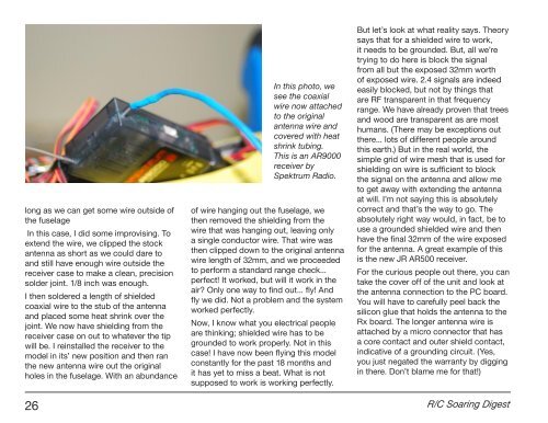
In this photo, we<br />
see the coaxial<br />
wire now attached<br />
to the original<br />
antenna wire and<br />
covered with heat<br />
shrink tubing.<br />
This is an AR9000<br />
receiver by<br />
Spektrum Radio.<br />
of wire hanging out the fuselage, we<br />
then removed the shielding from the<br />
wire that was hanging out, leaving only<br />
a single conductor wire. That wire was<br />
then clipped down to the original antenna<br />
wire length of 32mm, and we proceeded<br />
to perform a standard range check...<br />
perfect! It worked, but will it work in the<br />
air Only one way to find out... fly! And<br />
fly we did. Not a problem and the system<br />
worked perfectly.<br />
Now, I know what you electrical people<br />
are thinking; shielded wire has to be<br />
grounded to work properly. Not in this<br />
case! I have now been flying this model<br />
constantly for the past 18 months and<br />
it has yet to miss a beat. What is not<br />
supposed to work is working perfectly.<br />
But let’s look at what reality says. Theory<br />
says that for a shielded wire to work,<br />
it needs to be grounded. But, all we’re<br />
trying to do here is block the signal<br />
from all but the exposed 32mm worth<br />
of exposed wire. 2.4 signals are indeed<br />
easily blocked, but not by things that<br />
are RF transparent in that frequency<br />
range. We have already proven that trees<br />
and wood are transparent as are most<br />
humans. (There may be exceptions out<br />
there... lots of different people around<br />
this earth.) But in the real world, the<br />
simple grid of wire mesh that is used for<br />
shielding on wire is sufficient to block<br />
the signal on the antenna and allow me<br />
to get away with extending the antenna<br />
at will. I’m not saying this is absolutely<br />
correct and that’s the way to go. The<br />
absolutely right way would, in fact, be to<br />
use a grounded shielded wire and then<br />
have the final 32mm of the wire exposed<br />
for the antenna. A great example of this<br />
is the new JR AR500 receiver.<br />
For the curious people out there, you can<br />
take the cover off of the unit and look at<br />
the antenna connection to the PC board.<br />
You will have to carefully peel back the<br />
silicon glue that holds the antenna to the<br />
Rx board. The longer antenna wire is<br />
attached by a micro connector that has<br />
a core contact and outer shield contact,<br />
indicative of a grounding circuit. (Yes,<br />
you just negated the warranty by digging<br />
in there. Don’t blame me for that!)<br />
26 R/C Soaring Digest