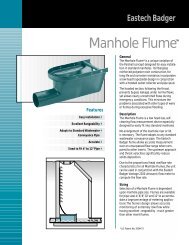
4600 IOM - Eastech Flow Controls
4600 IOM - Eastech Flow Controls
4600 IOM - Eastech Flow Controls

You also want an ePaper? Increase the reach of your titles
YUMPU automatically turns print PDFs into web optimized ePapers that Google loves.
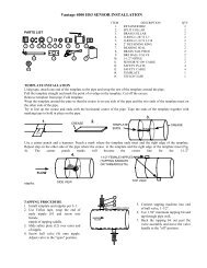
Sensor Cable Preparation<br />
Sensor cable connections. Before pulling the sensor cables through the conduit, mark the ends of the cables to<br />
indicate which is the upstream and downstream sensor cable. Leave approximately 8 inches of cable<br />
extending from the conduit in the enclosure. Prepare the cable ends in the following manner.<br />
1. Remove outer cable cover. Measure 1-5/8" from the end of the cable. With a cutting tool,<br />
carefully cut through the outer covering completely around the cable making sure not to cut into the<br />
outer shield. Make another cut from the first cut to the end of the cable and remove the outer cover.<br />
2. Remove outer shield. Measure 1-1/4" from the end of the cable with a pair of small cutters, cut<br />
the shield around the cable at the measured point and remove the cut off shield.<br />
3. Remove middle cover. Measure 1" from the end of the cable. With a cutting tool, carefully cut<br />
through the middle covering completely around the cable making sure not to cut into the middle<br />
shield. Make another cut from the first cut to the end of the cable and remove the middle cover.<br />
4. Remove middle shield. Measure 5/8" from the end of the cable. With a pair of small cutters, cut<br />
the shield around the cable at the measured point and remove the cut off shield.<br />
5. Remove inner cover. Measure 3/8" from the end of the cable. With a cutting tool or pair of wire<br />
strippers, carefully cut the inner covering completely around the cable, making sure not to cut into the<br />
center conductor and remove the inner cover.<br />
After the ends of the cables have been prepared, loosen the screws on the sensor inputs at the lower<br />
left corner of the PCB and remove the two pairs of clamps. Take the upstream cable and insert the<br />
center conductor into the top terminal of the upstream sensor and tighten the screw. Slightly pull on<br />
the cable to ensure the wire is secured to the terminal. Take the downstream cable and insert the<br />
center conductor into the top terminal of the downstream sensor and tighten the screw. Slightly pull<br />
on the cable to ensure the wire is secured to the terminal.<br />
Place the two pair of clamps over the middle and outer shields and secure them into place. Verify<br />
that the clamps are making good contact with the shields and that no wires of the shields are<br />
extending beyond their own clamp down area.<br />
Vantage 4000 2-4