


Create successful ePaper yourself
Turn your PDF publications into a flip-book with our unique Google optimized e-Paper software.
<strong>CABLE</strong> <strong>CONTROLS</strong><br />
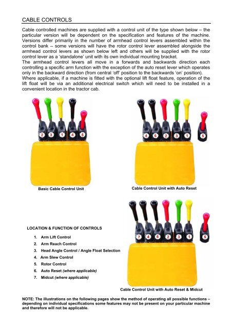
Cable controlled machines are supplied with a control unit of the type shown below – the<br />
particular version will be dependent on the specification and features of the machine.<br />
Versions differ primarily in the number of armhead control levers assembled within the<br />
control bank – some versions will have the rotor control lever assembled alongside the<br />
armhead control levers as shown below left and others will be supplied with the rotor<br />
control lever as a ‘standalone’ unit with its own individual mounting bracket.<br />
The armhead control levers all move in a forwards and backwards direction each<br />
controlling a specific arm function with the exception of the auto reset lever which operates<br />
only in the backward direction (from central ‘off’ position to the backwards ‘on’ position).<br />
Where applicable, if a machine is fitted with the optional lift float feature, operation of the<br />
lift float will be via an additional electrical switch which will need to be installed in a<br />
convenient location in the tractor cab.<br />
Basic Cable Control Unit<br />
Cable Control Unit with Auto Reset<br />
LOCATION & FUNCTION OF <strong>CONTROLS</strong><br />
1. Arm Lift Control<br />
2. Arm Reach Control<br />
3. Head Angle Control / Angle Float Selection<br />
4. Arm Slew Control<br />
5. Rotor Control<br />
6. Auto Reset (where applicable)<br />
7. Midcut (where applicable)<br />
Cable Control Unit with Auto Reset & Midcut<br />
NOTE: The illustrations on the following pages show the method of operating all possible functions –<br />
depending on individual specifications some features may not be present on your particular machine<br />
and therefore will not be applicable.
ARM OPERATION<br />
Auto<br />
Reset
Rotor Control<br />
Refer to specific cable rotor control section<br />
for additional information on rotor operation<br />
Midcut Models<br />
FLOAT OPERATION (Angle Float standard/ Lift Float optional)<br />
HEAD ANGLE FLOAT -<br />
Push angle lever fully<br />
forward into the detent<br />
position.<br />
A) Angle Float OFF B) Angle Float ON<br />
Lift Float (where applicable)<br />
A) Lift Float OFF B) Lift Float ON
<strong>CABLE</strong> ROTOR CONTROL<br />
On cable rotor control machines the rotor is operated by the lever shown below – from the<br />
upright ‘off’ position pushing the lever forward switches the rotor on for downhill cutting and<br />
pulling the lever backwards switches the rotor on for uphill cutting. The small pivot locking<br />
lever mounted on the side of the control assembly rotates through 180° to lock the rotor in<br />
a specific cutting direction – this is a safety feature to avoid changes of rotor direction<br />
without first stopping the rotor. To change the direction of cut the rotor lever must be<br />
placed in the upright ‘off’ position; when the rotor has stopped rotating completely the pivot<br />
locking lever can be turned to the opposing position allowing the control lever to be<br />
operated for opposite cutting direction.<br />
On some cable operated machines the rotor control lever will be assembled as part of the<br />
main bank of controls, whereas on others and all electric models it will be supplied as a<br />
‘standalone’ unit with its own mounting bracket.<br />
UPHILL CUTTING<br />
Lock<br />
DOWNHILL CUTTING<br />
Lock<br />
CAUTION: Ensure the rotor has stopped turning completely before attempting to change<br />
direction - When switched off a rotor can continue to ‘freewheel’ under its own momentum<br />
for up to 40 seconds before stopping.


