Design of a Communication System Based on IEEE ... - IRNet Explore
Design of a Communication System Based on IEEE ... - IRNet Explore
Design of a Communication System Based on IEEE ... - IRNet Explore

Create successful ePaper yourself
Turn your PDF publications into a flip-book with our unique Google optimized e-Paper software.
<str<strong>on</strong>g>Design</str<strong>on</strong>g> <str<strong>on</strong>g>of</str<strong>on</strong>g> a <str<strong>on</strong>g>Communicati<strong>on</strong></str<strong>on</strong>g><br />
<str<strong>on</strong>g>System</str<strong>on</strong>g> <str<strong>on</strong>g>Based</str<strong>on</strong>g> <strong>on</strong><br />
<strong>IEEE</strong> 804.15.4<br />
for Telemedical Applicati<strong>on</strong>s<br />
G C Madhu, T.Reshma, N. Suvarna, K.Nomitha Raj & Y. .I.Swetha<br />
Sree Vidyanikethan Engineering College, Department <str<strong>on</strong>g>of</str<strong>on</strong>g> Electr<strong>on</strong>ics and<br />
C<strong>on</strong>trol Engineering<br />
E-mail : msnaidu417@gmail.com, reshma.krc@gmail.com<br />
Abstract - This paper deals with<br />
the design and implementati<strong>on</strong>n <str<strong>on</strong>g>of</str<strong>on</strong>g> the prototype<br />
<str<strong>on</strong>g>of</str<strong>on</strong>g> a Digital communicati<strong>on</strong> system that transmits all<br />
the informati<strong>on</strong> from <strong>on</strong>e point<br />
to another using an Xbee c<strong>on</strong>troller. To test this system we have chosen to transmit the values <str<strong>on</strong>g>of</str<strong>on</strong>g><br />
Blood Pressure, body Temperature and positi<strong>on</strong><br />
<str<strong>on</strong>g>of</str<strong>on</strong>g> a patient from<br />
home place to<br />
the doctor room.<br />
Keywords- Sensors, Xbee module, LabVIEW, Digital <str<strong>on</strong>g>Communicati<strong>on</strong></str<strong>on</strong>g>.<br />
I. INTRODUCTION<br />
The present technological evoluti<strong>on</strong> is leading to<br />
many new forms <str<strong>on</strong>g>of</str<strong>on</strong>g> revoluti<strong>on</strong>ary needs that meet the<br />
needs <str<strong>on</strong>g>of</str<strong>on</strong>g> patients. In order to improve<br />
elderly life<br />
c<strong>on</strong>diti<strong>on</strong>s at home and to<br />
reduce the costs <str<strong>on</strong>g>of</str<strong>on</strong>g> l<strong>on</strong>g<br />
hospitalizati<strong>on</strong>s, the medical world is more and more<br />
interested in<br />
telem<strong>on</strong>itoring<br />
techniques.<br />
These<br />
techniques will allow elderly people to stay safely at<br />
home, to benefit from an automated medical supervisi<strong>on</strong><br />
and will delay<br />
their entrancee in nursing homes. Medical<br />
pr<str<strong>on</strong>g>of</str<strong>on</strong>g>essi<strong>on</strong>als believe that <strong>on</strong>e <str<strong>on</strong>g>of</str<strong>on</strong>g> the best ways to detect<br />
emerging physical and mental health problems, before it<br />
becomes critical (particularly for the elderly), is<br />
analyzing the human behaviour and looking for changes<br />
in the activities <str<strong>on</strong>g>of</str<strong>on</strong>g> daily living (ADLs).<br />
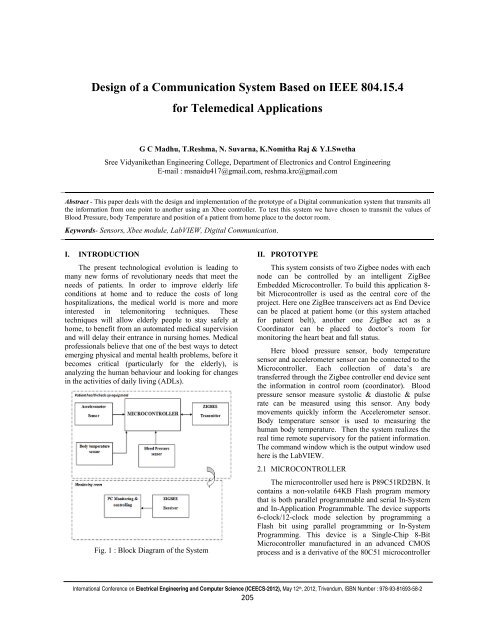
Fig. 1 : Block Diagram <str<strong>on</strong>g>of</str<strong>on</strong>g> the <str<strong>on</strong>g>System</str<strong>on</strong>g><br />
II. PROTOTYPE<br />
This<br />
system c<strong>on</strong>sists <str<strong>on</strong>g>of</str<strong>on</strong>g> two Zigbee nodes with<br />
each<br />
node can be c<strong>on</strong>trolled by an intelligent ZigBee<br />
Embedded Microc<strong>on</strong>troller. To build<br />
this applicati<strong>on</strong> 8-<br />
bit Microc<strong>on</strong>troller is used as the central core <str<strong>on</strong>g>of</str<strong>on</strong>g> the<br />
project. Here <strong>on</strong>e ZigBee transceivers act as End Device<br />
can be placed at patient home (or this system attached<br />
for patient belt), another <strong>on</strong>e ZigBee act as a<br />
Coordinator can be placed to doctor’s room<br />
for<br />
m<strong>on</strong>itoring the heart beat and fall status.<br />
Here blood pressure sensor, body temperature<br />
sensor and accelerometer sensor can be c<strong>on</strong>nected to the<br />
Microc<strong>on</strong>troller.<br />
Each<br />
collecti<strong>on</strong><br />
<str<strong>on</strong>g>of</str<strong>on</strong>g> data’s are<br />
transferred through the<br />
Zigbee c<strong>on</strong>troller end device sent<br />
the informati<strong>on</strong> in c<strong>on</strong>trol room (coordinator). Blood<br />
pressuree sensor measure systolic & diastolic & pulse<br />
rate can<br />
be measured using this sensor. Any body<br />
movements quickly inform the Accelerometer sensor.<br />
Body temperature sensor is used to measuring<br />
the<br />
human body temperature. Then the system realizes the<br />
real time<br />
remote supervisory for the patient informati<strong>on</strong>.<br />
The command windoww which is the output windoww used<br />
here is the LabVIEW.<br />
2.1 MICROCONTROLLER<br />
The<br />
microc<strong>on</strong>troller used here is<br />
P89C51RD2BN. It<br />
c<strong>on</strong>tains<br />
a n<strong>on</strong>-volatile 64KB Flash<br />
program memory<br />
that is both parallel programmable and serial In-<str<strong>on</strong>g>System</str<strong>on</strong>g><br />
and In-Applicati<strong>on</strong> Programmable. The device supports<br />
6-clock/ /12-clock mode selecti<strong>on</strong> by programming a<br />
Flash bit using parallel programming or In-<str<strong>on</strong>g>System</str<strong>on</strong>g><br />
Programming. This device is a Single-Chip 8-Bit<br />
Microc<strong>on</strong>troller manufactured in an<br />
advanced CMOS<br />
process and is a derivative <str<strong>on</strong>g>of</str<strong>on</strong>g> the 80C51 microc<strong>on</strong>troller<br />
Internati<strong>on</strong>al C<strong>on</strong>ference <strong>on</strong> Electrical Engineering and Computer Science (ICEECS-2012), May 12 th , 2012, Trivendum, ISBN Number : 978-93-81693-58-2<br />
205
<str<strong>on</strong>g>Design</str<strong>on</strong>g> <str<strong>on</strong>g>of</str<strong>on</strong>g> a <str<strong>on</strong>g>Communicati<strong>on</strong></str<strong>on</strong>g> <str<strong>on</strong>g>System</str<strong>on</strong>g> <str<strong>on</strong>g>Based</str<strong>on</strong>g> <strong>on</strong> <strong>IEEE</strong> 804.15.4 for Telemedical Applicati<strong>on</strong>s<br />
family. The device also has four 8-bit I/O ports, three<br />
16-bit timer/event counters, a multi-source, and fourpriority-level,<br />
nested interrupt structure, an enhanced<br />
UART and <strong>on</strong>-chip oscillator and timing circuits. The<br />
added features <str<strong>on</strong>g>of</str<strong>on</strong>g> the P89C51RD2BN make it a<br />
powerful microc<strong>on</strong>troller for applicati<strong>on</strong>s that require<br />
pulse width modulati<strong>on</strong>, high-speed I/O and up/down<br />
counting capabilities such as motor c<strong>on</strong>trol.<br />
2.2 SENSORS<br />
Here we used three sensors to find the three<br />
parameters <str<strong>on</strong>g>of</str<strong>on</strong>g> a patient. A pressure sensor to find the<br />
blood pressure using a digital blood pressure meter is<br />
used. The temperature <str<strong>on</strong>g>of</str<strong>on</strong>g> the body is measured using a<br />
temperature sensor called LM35. For the positi<strong>on</strong> and<br />
movements <str<strong>on</strong>g>of</str<strong>on</strong>g> the body, an accelerometer sensor<br />
ADXL335 is used. These sensors are interfaced with the<br />
microc<strong>on</strong>troller.<br />
2.2.1 BLOOD PRESSURE SENSOR<br />
The method used in electr<strong>on</strong>ics systems for<br />
measuring blood pressure is the oscillometric method.<br />
The pressure sensor is c<strong>on</strong>nected directly to the cuff,<br />
which is inflated or deflated via a motor and valve.<br />
voltage is linearly proporti<strong>on</strong>al to the Celsius<br />
(Centigrade) temperature. The LM35 thus has an<br />
advantage over linear temperature sensors calibrated in °<br />
Kelvin, as the user is not required to subtract a large<br />
c<strong>on</strong>stant voltage from its output to obtain c<strong>on</strong>venient<br />
Centigrade scaling.<br />
Fig. 3: Temperature Sensor LM35<br />
The LM35 does not require any external calibrati<strong>on</strong><br />
or trimming to provide typical accuracies <str<strong>on</strong>g>of</str<strong>on</strong>g> ±1⁄4°C at<br />
room temperature and ±3⁄4°C over a full −55 to +150°C<br />
temperature range. Low cost is assured by trimming and<br />
calibrati<strong>on</strong> at the wafer level. The LM35’s low output<br />
impedance, linear output, and precise inherent<br />
calibrati<strong>on</strong> make interfacing to readout or c<strong>on</strong>trol<br />
circuitry especially easy.<br />
2.2.3 ACCERELOMETER SENSOR<br />
The ADXL335 is a small, thin, low power,<br />
complete 3-axis accelerometer with Signal c<strong>on</strong>diti<strong>on</strong>ed<br />
voltage outputs. The product measures accelerati<strong>on</strong> with<br />
a minimum full-scale range <str<strong>on</strong>g>of</str<strong>on</strong>g> ±3 g. It can measure the<br />
static accelerati<strong>on</strong> <str<strong>on</strong>g>of</str<strong>on</strong>g> gravity in tilt-sensing applicati<strong>on</strong>s,<br />
as well as dynamic accelerati<strong>on</strong> resulting from moti<strong>on</strong>,<br />
shock, or vibrati<strong>on</strong>.<br />
Fig. 2 : Digital Blood Pressure meter<br />
Digital Blood Pressure Meter uses an integrated<br />
pressure sensor, analog signal-c<strong>on</strong>diti<strong>on</strong>ing circuitry,<br />
microc<strong>on</strong>troller hardware/s<str<strong>on</strong>g>of</str<strong>on</strong>g>tware and a liquid crystal<br />
display. The sensing system reads the cuff pressure (CP)<br />
and extracts the pulses for analysis and determinati<strong>on</strong> <str<strong>on</strong>g>of</str<strong>on</strong>g><br />
systolic and diastolic pressure. This design uses a 50<br />
kPa integrated pressure yielding a pressure range <str<strong>on</strong>g>of</str<strong>on</strong>g> 0<br />
mm Hg to 300 mm Hg.<br />
2.2.2 TEMPERATURE SENSOR<br />
The LM35 series sensors used here are precisi<strong>on</strong><br />
integrated-circuit temperature sensors, whose output<br />
Fig.4 : Accelerometer Sensor ADXL335<br />
The user selects the bandwidth <str<strong>on</strong>g>of</str<strong>on</strong>g> the accelerometer<br />
using the CX, CY, and CZ capacitors at the XOUT,<br />
YOUT, and ZOUT pins. Bandwidths can be selected to<br />
suit the applicati<strong>on</strong>, with a range <str<strong>on</strong>g>of</str<strong>on</strong>g> 0.5 Hz to 1600 Hz<br />
for the X and Y axes, and a range <str<strong>on</strong>g>of</str<strong>on</strong>g> 0.5 Hz to 550 Hz<br />
for the Z axis.<br />
Internati<strong>on</strong>al C<strong>on</strong>ference <strong>on</strong> Electrical Engineering and Computer Science (ICEECS-2012), May 12 th , 2012, Trivendum, ISBN Number : 978-93-81693-58-2<br />
206
<str<strong>on</strong>g>Design</str<strong>on</strong>g> <str<strong>on</strong>g>of</str<strong>on</strong>g> a <str<strong>on</strong>g>Communicati<strong>on</strong></str<strong>on</strong>g> <str<strong>on</strong>g>System</str<strong>on</strong>g> <str<strong>on</strong>g>Based</str<strong>on</strong>g> <strong>on</strong> <strong>IEEE</strong> 804.15.4 for Telemedical Applicati<strong>on</strong>s<br />
Fig. 5. Transmitter part <str<strong>on</strong>g>of</str<strong>on</strong>g> the overall system<br />
Fig. 6. A Zigbee Network<br />
Zigbee is a wireless communicati<strong>on</strong>s standard that<br />
provides a short-range cost effective networking<br />
capability. It has been developed with the emphasis <strong>on</strong><br />
low-cost, battery-powered applicati<strong>on</strong>s, such as building<br />
automati<strong>on</strong>, industrial and wireless, pers<strong>on</strong>al healthcare<br />
and advanced tagging.<br />
Fig. 6. Receiver part <str<strong>on</strong>g>of</str<strong>on</strong>g> the overall system<br />
2.3 COMMUNICATION<br />
The data from the patient needs to be transmitted<br />
from the patient’s room to the doctor’s room. In this<br />
project wireless communicati<strong>on</strong> is used through the<br />
Xbee module. It c<strong>on</strong>sists <str<strong>on</strong>g>of</str<strong>on</strong>g> a transmitter and receiver<br />
both based <strong>on</strong> Zigbee Protocol. Zigbee is specifically<br />
designed to provide a cost-effective, standard-based and<br />
flexible wireless network, which supports low power<br />
c<strong>on</strong>sumpti<strong>on</strong>, reliability, interoperability and security for<br />
c<strong>on</strong>trol and m<strong>on</strong>itoring applicati<strong>on</strong>s with low to<br />
moderate data rates.<br />
The Xbee module can transmit low data rate<br />
through a distance <str<strong>on</strong>g>of</str<strong>on</strong>g> about 50m. The communicati<strong>on</strong><br />
card is essentially based <strong>on</strong> the Xbee module, the<br />
microc<strong>on</strong>troller and the USB port. It can provide the<br />
communicati<strong>on</strong> between PC-Xbee, the communicati<strong>on</strong><br />
between PIC-Xbee and the communicati<strong>on</strong> between<br />
PIC-PC. In additi<strong>on</strong>, it allows users to make Analog to<br />
Digital c<strong>on</strong>versi<strong>on</strong> to <strong>on</strong>e <str<strong>on</strong>g>of</str<strong>on</strong>g> the five analog inputs. The<br />
presence <str<strong>on</strong>g>of</str<strong>on</strong>g> the microc<strong>on</strong>troller <strong>on</strong> the card is mandatory<br />
as it is c<strong>on</strong>sidered as the brain <str<strong>on</strong>g>of</str<strong>on</strong>g> the card. Indeed, it<br />
manages all communicati<strong>on</strong> and determines the mode <str<strong>on</strong>g>of</str<strong>on</strong>g><br />
communicati<strong>on</strong>s and run the Analog to Digital<br />
C<strong>on</strong>versi<strong>on</strong>.<br />
III. LABVIEW<br />
LabVIEW (Laboratory Virtual Instrument<br />
Engineering Workbench) is a graphical programming<br />
language that uses ic<strong>on</strong>s instead <str<strong>on</strong>g>of</str<strong>on</strong>g> lines <str<strong>on</strong>g>of</str<strong>on</strong>g> text to create<br />
applicati<strong>on</strong>s. In c<strong>on</strong>trast to text-based programming<br />
languages, where instructi<strong>on</strong>s determine the order <str<strong>on</strong>g>of</str<strong>on</strong>g><br />
program executi<strong>on</strong>, LabVIEW uses dataflow<br />
programming. VIs or virtual instruments, is LabVIEW<br />
programs that imitate physical instruments.<br />
LabVIEW is used to communicate with hardware<br />
such as data acquisiti<strong>on</strong>, visi<strong>on</strong>, and moti<strong>on</strong> c<strong>on</strong>trol<br />
devices, and industrial automati<strong>on</strong> <strong>on</strong> a variety <str<strong>on</strong>g>of</str<strong>on</strong>g><br />
platforms including Micros<str<strong>on</strong>g>of</str<strong>on</strong>g>t Windows, various<br />
versi<strong>on</strong>s <str<strong>on</strong>g>of</str<strong>on</strong>g> UNIX, Linux. LabVIEW c<strong>on</strong>tains a<br />
comprehensive set <str<strong>on</strong>g>of</str<strong>on</strong>g> tools for acquiring, analyzing,<br />
displaying, and storing data.<br />
Fig. 7. LabVIEW output at the doctor’s screen<br />
Internati<strong>on</strong>al C<strong>on</strong>ference <strong>on</strong> Electrical Engineering and Computer Science (ICEECS-2012), May 12 th , 2012, Trivendum, ISBN Number : 978-93-81693-58-2<br />
207
<str<strong>on</strong>g>Design</str<strong>on</strong>g> <str<strong>on</strong>g>of</str<strong>on</strong>g> a <str<strong>on</strong>g>Communicati<strong>on</strong></str<strong>on</strong>g> <str<strong>on</strong>g>System</str<strong>on</strong>g> <str<strong>on</strong>g>Based</str<strong>on</strong>g> <strong>on</strong> <strong>IEEE</strong> 804.15.4 for Telemedical Applicati<strong>on</strong>s<br />
IV. EXPERIMENTAL RESULTS<br />
To test this prototype many experiments have been<br />
d<strong>on</strong>e with many patients to evaluate the quality <str<strong>on</strong>g>of</str<strong>on</strong>g><br />
transmissi<strong>on</strong> from different distances. Initially when it is<br />
tested with <strong>on</strong>e patient at a distance less than 10m, all<br />
the parameters that were measured are accurately<br />
transmitted through the Xbee module to the receiver<br />
secti<strong>on</strong> without any error.<br />
Next it was repeated for gradually increasing<br />
distances. Every time there was an accurate transmissi<strong>on</strong><br />
<str<strong>on</strong>g>of</str<strong>on</strong>g> the data from the transmitter to the receiver.<br />
V. CONCLUSION<br />
In this prototype the biological data from the patient<br />
to the doctor’s screen is transmitted via a wireless digital<br />
communicati<strong>on</strong>. As this prototype is used for <strong>on</strong>ly a<br />
distance <str<strong>on</strong>g>of</str<strong>on</strong>g> about 50m using the Xbee module, in future<br />
this can be extended to a more farther distances<br />
efficiently.<br />
REFERENCES<br />
[1] Nadia Ghariani, M<strong>on</strong>dher Chaoui, Hamadi<br />
Ghariani, M<strong>on</strong>gi Lahiani “<str<strong>on</strong>g>Design</str<strong>on</strong>g> Of A Digital<br />
<str<strong>on</strong>g>Communicati<strong>on</strong></str<strong>on</strong>g> <str<strong>on</strong>g>System</str<strong>on</strong>g> <str<strong>on</strong>g>Based</str<strong>on</strong>g> On a XBee<br />
Module For Biomedical Applicati<strong>on</strong>s”, in 8th<br />
Internati<strong>on</strong>al Multi-C<strong>on</strong>ference <strong>on</strong> <str<strong>on</strong>g>System</str<strong>on</strong>g>s,<br />
Signals & Devices.<br />
[2] S. Borromeo, C. Rodriguez-Sanchez, F.<br />
Machado, J.A. Hernandez-Tamames, R. de la<br />
Prieta, “A Rec<strong>on</strong>figurable, Wearable, Wireless<br />
ECG <str<strong>on</strong>g>System</str<strong>on</strong>g>”, in 29th Annual Internati<strong>on</strong>al<br />
C<strong>on</strong>ference <str<strong>on</strong>g>of</str<strong>on</strong>g> the <strong>IEEE</strong> EMBS, France, August<br />
23-26, 2007, pp.1659-1662<br />
[3] C. Ken, L. Xiaoying, “A Zigbee <str<strong>on</strong>g>Based</str<strong>on</strong>g> Mesh<br />
Network for ECG M<strong>on</strong>itoring <str<strong>on</strong>g>System</str<strong>on</strong>g>”, in 4th<br />
Internati<strong>on</strong>al C<strong>on</strong>ference <str<strong>on</strong>g>of</str<strong>on</strong>g> Bioinformatics and<br />
Biomedical Engineering (iCBBE), 2010, pp. 1-4<br />
[4] Yu-Cheng, Su Huan, Chen Ching-Lun, Hung<br />
Shuenn-Yuh Lee, “Wireless ECG detecti<strong>on</strong><br />
system with low-power analog fr<strong>on</strong>t-end circuit<br />
and bio-processing ZigBee firmware”, in<br />
Proceedings <str<strong>on</strong>g>of</str<strong>on</strong>g> 2010 <strong>IEEE</strong> Internati<strong>on</strong>al<br />
Symposium <strong>on</strong> Circuits and <str<strong>on</strong>g>System</str<strong>on</strong>g>s (ISCAS),<br />
2010, p 1216 – 1219<br />
[5] http://www.laboratoiresdelaretine.com/<br />
dmla/wpc<strong>on</strong>tent/up loads/AQDMtelemedicine.pdf\<br />
[6] http://www.digi.com/products/wireless/zigbeemesh/xbeedigimesh-2-4.jsp#overview<br />
[7] V. Auteri, C. Lamberti, L. R<str<strong>on</strong>g>of</str<strong>on</strong>g>fia, and T. S.<br />
Cinotti, "ZigBee-based wireless ECG m<strong>on</strong>itor",<br />
in Computers in Cardiology 2007 (CINC07),<br />
2007, pp. 133-136.<br />
<br />
Internati<strong>on</strong>al C<strong>on</strong>ference <strong>on</strong> Electrical Engineering and Computer Science (ICEECS-2012), May 12 th , 2012, Trivendum, ISBN Number : 978-93-81693-58-2<br />
208