Walk-Through For Mills - Haas Automation, Inc.
Walk-Through For Mills - Haas Automation, Inc.
Walk-Through For Mills - Haas Automation, Inc.

Create successful ePaper yourself
Turn your PDF publications into a flip-book with our unique Google optimized e-Paper software.
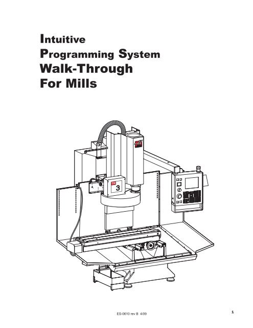
Intuitive<br />
Programming System<br />
<strong>Walk</strong>-<strong>Through</strong><br />
<strong>For</strong> <strong>Mills</strong><br />
3<br />
ES-0610 rev B 4/09<br />
1
In t r o d u c t i o n<br />
These instructions provide an in-depth look at each of the Intuitive Programming System (IPS) menus and<br />
are to be used with the Mill Operator’s manual (96-8000). A more formal description is given for each of the<br />
entries to help better define the on-screen help for new users.<br />
A program created through IPS is also accessible in MDI mode. The program can be edited and saved to<br />
memory from the full CNC mode, or run in graphics.<br />
Ac c e s s i n g IPS<br />
Software versions prior to 16.xx: The IPS menu is displayed at power up. The IPS initial screen displays<br />
current Axis positions and a spindle status (direction / speed) indicator.<br />
16.xx and later: To access IPS, press MDI/DNC, then PRGRM/CONVRS. The IPS tabbed menu appears in<br />
the upper-right display pane. Axis positions and spindle status are always available in their respective panes.<br />
NOTE: Some IPS functions vary on 15” display machines, depending on the software<br />
version your lathe is equipped with. Where significant differences exist, they are<br />
indicated as seen above, or in separate sections. Please verify your software version<br />
and ensure that you are following the correct instructions. Please refer to “software<br />
version identification” at the end of this document if you are not sure how to check<br />
your software version.<br />
Me n u Nav i g at i o n<br />
Navigate tabbed menus using the left and right arrow keys. To select a menu item, press Write/Enter. Some<br />
menus have sub-tabs; in this case, use the left and right arrow keys and press Write/Enter to select.<br />
Use the arrow keys to navigate through the input fields, enter values using the number pad, and then press<br />
Write/Enter.<br />
Press Cancel to go back one menu level. Pressing Cancel at a top-level menu exits IPS.<br />
Pressing any of the buttons under the “Display” heading will also exit the IPS menus, as will any of the mode<br />
keys (i.e. Edit, Mem, MDI, etc.).<br />
Software versions prior to 16.xx: To return to the IPS menu, press HAND JOG.<br />
16.xx and later: To return to the IPS menu, press MDI/DNC, then PRGRM/CONVRS.<br />
NOTE: Depending on the software version currently installed on the mill, the machine menu<br />
displays may vary slightly from those pictured in this manual. Unless indicated<br />
otherwise, these differences are simply cosmetic.<br />
ES-0610 rev B 4/09<br />
2
Ma n u a l Mo d e<br />
Power on the machine and press RESET until all alarms have cleared. Press POWER ON/RESTART to zero<br />
the machine. The IPS menu can now be accessed by pressing MDI DNC, then pressing PRGRM CONVRS.<br />
Press WRITE/ENTER to display the IPS menu MANUAL tab.<br />
MANUAL SETUP FACE DRILL POCKET MILLING ENGRAVING VQC<br />
X AND Y AXES<br />
The axes can be electronically locked and unlocked. This is shown by<br />
XY-MAN displayed at the bottom ofthe screen. In this mode both the<br />
X and Y axes are unlocked and can be positioned using the manual hand<br />
wheels. Pressing SHIFT and either +X or -X, or+Yor-Ywill<br />
electronically lock that axis. Pressing SHIFT and the same button a<br />
second time will unlock the axis.<br />
SPINDLE<br />
The spindle is commanded by entering avalue for the spindle speed<br />
and pressing either the CWor CCW button. The spindle speed<br />
override keys (+/-10%) can be used to adjust the commanded speed.<br />
15” Display Shown<br />
X and Y Axes<br />
Just below the on-screen text is a line of text that shows the state the mill is in. <strong>For</strong> example, “X -MAN” means<br />
the X -axis is in manual mode (i.e., you can turn the X-axis handwheel, but not the Y-axis). No text beneath<br />
the on-screen help means that both axes (X and Y) are locked. In this case, the axes can be jogged by pressing<br />
+X/-X or +Y/-Y or by using the electronic jog handle on the pendant. Select a jog speed before using the<br />
jog handle. To quickly return to the manual handwheel mode, press Write/Enter while in the Manual tab (look<br />
for XY-MAN to be displayed), or from a different tab, press the Shift key and X, then the Shift key and Y.<br />
Spindle<br />
The spindle is controlled using keys on the control pendant. Enter a spindle speed; for example, press 5, then<br />
0, then Write/Enter. This will enter a speed of 50 RPM. Ensure the area around the spindle is free of tools and<br />
workpieces, press the hold to run switch and then press either the FWD or REV button. The spindle speed<br />
override keys (+/- 10%) can be used to adjust the commanded speed. This also works on most screens.<br />
The spindle is stopped by letting go of the hold to run switch, pressing Reset, or pressing the Stop button.<br />
ES-0610 rev B 4/09<br />
3
Se t u p Mo d e<br />
Select Setup Mode by moving the highlighted tab to the Setup tab and pressing Write/Enter.<br />
Wo r k Ta b<br />
The Work tab is displayed by moving to the Work tab on the Setup screen and pressing Write/Enter. The<br />
Work tab is used to enter Work Offsets and to select the material. In order for the mill to accurately machine<br />
a work piece, it needs to know where the part is located on the table. Jog the mill with a pointer tool in the<br />
spindle, until it reaches the top left corner of the part. This position is part zero.<br />
MANUAL SETUP FACE<br />
Wrk Zero Ofst<br />
54<br />
XOffset<br />
-8.0000<br />
YOffset<br />
-8.0000<br />
DRILL POCKET MILLING ENGRAVING VQC<br />
Work Material<br />
LOW CARBON UNALLOYED STEEL<br />
ZOffset<br />
0.<br />
AOffset<br />
Disabled<br />
BOffset<br />
Disabled<br />
WORK<br />
TOOL<br />
TOOL PROBE CALIBRATION<br />
WORK PROBE CALIBRATION<br />
Offsets – Select the required Work Zero Offset by scrolling through the available choices and designating<br />
one. Select the X, Y and/or Z Offset setting, and enter a value. Press Write/Enter to add the value to the<br />
current value, F1 to set the value, or Part Zero Set to record current position.<br />
Work Material – Select the Work Material setting and use the Up and Down cursor arrows to change the<br />
material type. Press Write/Enter to select the material type.<br />
NOTE: Use “No Material Selected” to enter speeds and feeds for tools.<br />
To o l Ta b<br />
The Tool tab is displayed by moving to the Tool tab on the Setup Screen and pressing Write/Enter. The Tool<br />
tab is used to set up the tools used in the milling operation.<br />
MANUAL SETUP FACE DRILL POCKET MILLING ENGRAVING VQC<br />
Press ATC FWD<br />
or ATC REV to<br />
change the tool<br />
displayed.<br />
Press NEXT TOOL<br />
to change the<br />
tool in spindle.<br />
Tool in Spindle: 1<br />
Tool Displayed: 1<br />
Tool Type<br />
DRILL<br />
Tool Diameter<br />
0.0000 in<br />
Point<br />
OFF<br />
Flutes<br />
2<br />
Z Length<br />
0.0000 in<br />
ZWear<br />
0.0000 in<br />
Spindle RPM<br />
0<br />
Tool Wear<br />
0.0000 in<br />
Coolant Pos<br />
0<br />
WORK<br />
TOOL<br />
Tool Type Parameters - Drill<br />
Tool Displayed (All Tools) – Current tool number. Use ATC FWD or ATC REV to change the tool displayed.<br />
Tool Type (All Tools) – Right/Left arrows select among 5 tools: Drill, Tap, Shell Mill, End Mill and Center Drill.<br />
ES-0610 rev B 4/09<br />
4
Tool Material (Drill, Shell Mill, End Mill, Center Drill) – Right/Left arrows select among 3 tool materials:<br />
Carbide, High Speed Steel and User.<br />
Tool Diameter (All Tools) – Enter the actual diameter/radius of the tool.<br />
Point (Drill, Center Drill) – Enter the included angle of the tool. Enter 0 or 180 to cancel.<br />
Flutes (All Tools) – Enter the number of flutes the tool has.<br />
Spindle RPM (All Tools) – Enter the spindle RPM for the tool, when the tool material is set to user.<br />
Feedrate (Drill, Shell Mill, End Mill, Center Drill) – Enter feedrate for tool, when tool material is set to user.<br />
TPI (Tap) – Enter the Threads per <strong>Inc</strong>h for the tap tool.<br />
Z Length (All Tools) – Press TOOL OFFSET MEASUR to record the current position or enter a value.<br />
Z Wear (All Tools) – Enter the amount of wear to the tool length.<br />
Tool Wear (All Tools) – Enter the amount of wear to the tool’s diameter/radius.<br />
Coolant Pos (All Tools) – Enter the Coolant Spigot position.<br />
Fa c e Mo d e<br />
The Face Mode is displayed by moving to the Face tab and pressing Write/Enter. The Face tab is used to set<br />
up any tools to be used in the milling operation.<br />
Face milling is a form of milling that produces a flat surface, generally at right angles to the rotating axis of a<br />
cutter. The tool is usually an End Mill.<br />
MANUAL SETUP FACE<br />
END MILL TOOL<br />
0<br />
R PLANE<br />
DRILL POCKET MILLING ENGRAVING VQS<br />
0.2000 in.<br />
WRK ZERO OFST<br />
54<br />
X DIMENSION<br />
0.0000 in.<br />
DEPTH OF FACE<br />
0.0000 in.<br />
TOOL CLEARANCE<br />
0.0000 in.<br />
Y DIMENSION<br />
0.0000 in.<br />
Press <br />
to run in MDI or <br />
to record output to a<br />
program.<br />
Face Milling Parameters:<br />
END MILL TOOL – Enter the End Mill tool number.<br />
WRK ZERO OFST – Enter a work zero offset number.<br />
X DIMENSION – Enter the X dimension in width. Must be a positive value.<br />
Y DIMENSION – Enter the Y dimension in width. Must be a positive value.<br />
R PLANE – Enter the location of the retract point above the part.<br />
DEPTH OF FACE – Enter the Z dimension to be cut from the top of the part.<br />
TOOL TOLERANCE – Enter a dimension between the edge of the part and the edge of the tool.<br />
Advanced Users: In full CNC Mode, this is a G01 command.<br />
ES-0610 rev B 4/09<br />
5
Dr i l l Mo d e<br />
The Drill Mode is displayed by moving to the Drill tab and pressing Write/Enter. The Drill tab is used to set up<br />
the type of drilling to be done in the milling operation.<br />
Bo l t Ci r c l e Ta b<br />
The Bolt Circle tab is displayed in Drill Mode by selecting the tab and pressing Write/Enter. The Bolt Circle tab<br />
is used to set up drilling a number of holes in a circular pattern.<br />
MANUAL SETUP FACE<br />
DRILL POCKET MILLING ENGRAVING VQC<br />
CENTER DRILL<br />
0<br />
DRILL TOOL<br />
0<br />
TAPTOOL<br />
0<br />
CENTER DEPTH<br />
0.0000 in<br />
DRILL DEPTH<br />
0.0000 in<br />
TAP DEPTH<br />
0.0000 in<br />
CENTER PECK<br />
0.0000 in<br />
DRILL PECK<br />
0.0000 in<br />
WRK ZERO OFST<br />
54<br />
X CENTER PT<br />
0.0000 in<br />
R PLANE<br />
0.2000 in<br />
DIAMETER<br />
0.0000 in<br />
NUM OF HOLES<br />
0<br />
CENTER HOLE<br />
0<br />
Press <br />
to run in MDI or <br />
to record output to a<br />
program.<br />
Y CENTER PT<br />
0.0000 in<br />
ANGLE<br />
0.000 deg<br />
BOLT CIRCLE BOLT LINE SINGLE HOLE<br />
MULTIPLE HOLES<br />
Bolt Circle Parameters:<br />
CENTER DRILL – Enter the center drill tool number. Enter ‘0’ to skip center drilling cycle.<br />
CENTER DEPTH – Enter how deep the holes are to be drilled. Calculated point value will be added if active.<br />
CENTER PECK – Enter the distance for each peck move during center drilling.<br />
DRILL TOOL – Enter drill tool number. Enter ‘0’ to skip drilling cycle.<br />
DRILL DEPTH – Enter how deep the holes are to be drilled. Calculated point value will be added if active.<br />
DRILL PECK – Enter the distance for each peck move during drilling.<br />
TAP TOOL – Enter the tap tool number. Enter ‘0’ to skip tapping cycle.<br />
TAP DEPTH – Enter how deep the holes are to be tapped.<br />
WRK ZERO OFST – Enter a work zero offset number.<br />
X CENTER PT – Enter the X axis dimension reference point from work zero offset.<br />
Y CENTER PT – Enter the Y axis dimension reference point from work zero offset.<br />
R PLANE – Enter the location of the retract point above the part.<br />
DIAMETER – Enter the diameter of the bolt hole circle.<br />
ANGLE – Enter the starting angle of holes from the three o’clock position.<br />
NUM OF HOLES – Enter the number of holes to be drilled in the bolt circle pattern.<br />
CENTER HOLE – Do you want a hole in the center of the pattern Enter ‘0’ for NO and ‘1’ for YES.<br />
Advanced Users: In full CNC Mode, this is a G70 command.<br />
ES-0610 rev B 4/09<br />
6
Bo l t Li n e Ta b<br />
The Bolt Line tab is displayed in Drill Mode by selecting the tab and pressing Write/Enter. The Bolt Line tab is<br />
used to set up drilling a number of holes in a line.<br />
MANUAL SETUP FACE<br />
DRILL POCKET MILLING ENGRAVING VQC<br />
CENTER DRILL<br />
0<br />
DRILL TOOL<br />
0<br />
TAPTOOL<br />
0<br />
CENTER DEPTH<br />
0.0000 in<br />
DRILL DEPTH<br />
0.0000 in<br />
TAP DEPTH<br />
0.0000 in<br />
CENTER PECK<br />
0.0000 in<br />
DRILL PECK<br />
0.0000 in<br />
WRK ZERO OFST<br />
54<br />
X CENTER PT<br />
0.0000 in<br />
R PLANE<br />
0.2000 in<br />
DISTANCE<br />
0.0000 in<br />
NUM OF HOLES<br />
0<br />
Press <br />
to run in MDI or <br />
to record output to a<br />
program.<br />
Y CENTER PT<br />
0.0000 in<br />
START ANGLE<br />
0.000 deg<br />
BOLT CIRCLE BOLT LINE SINGLE HOLE<br />
MULTIPLE HOLES<br />
Bolt Line Parameters:<br />
CENTER DRILL – Enter the center drill tool number. Enter ‘0’ to skip center drilling cycle.<br />
CENTER DEPTH – Enter how deep the holes are to be drilled. Calculated point value will be added if active.<br />
CENTER PECK – Enter the distance for each peck move during center drilling.<br />
DRILL TOOL – Enter drill tool number. Enter ‘0’ to skip drilling cycle.<br />
DRILL DEPTH – Enter how deep the holes are to be drilled. Calculated point value will be added if active.<br />
DRILL PECK – Enter the distance for each peck move during drilling.<br />
TAP TOOL – Enter the tap tool number. Enter ‘0’ to skip tapping cycle.<br />
TAP DEPTH – Enter how deep the holes are to be tapped.<br />
WRK ZERO OFST – Enter a work zero offset number.<br />
X CENTER PT – Enter the X axis dimension reference point from work zero offset.<br />
Y CENTER PT – Enter the Y axis dimension reference point from work zero offset.<br />
R PLANE – Enter the location of the retract point above the part.<br />
DISTANCE – Enter the distance between the holes. Must be a positive value.<br />
START ANGLE – Enter the starting angle of holes from the three o’clock position.<br />
NUM OF HOLES – Enter the number of holes to be drilled in a linear path.<br />
Advanced Users: In full CNC Mode, this is a G72 command.<br />
ES-0610 rev B 4/09<br />
7
Si n g l e Ho l e Ta b<br />
The Single Hole tab is displayed in Drill Mode by selecting the tab and pressing Write/Enter. The Single Hole<br />
tab is used to set up drilling a single hole.<br />
MANUAL SETUP FACE<br />
DRILL POCKET MILLING ENGRAVING VQC<br />
CENTER DRILL<br />
0<br />
DRILL TOOL<br />
0<br />
TAPTOOL<br />
0<br />
CENTER DEPTH<br />
0.0000 in<br />
DRILL DEPTH<br />
0.0000 in<br />
TAP DEPTH<br />
0.0000 in<br />
CENTER PECK<br />
0.0000 in<br />
DRILL PECK<br />
0.0000 in<br />
WRK ZERO OFST<br />
54<br />
X CENTER PT<br />
0.0000 in<br />
Y CENTER PT<br />
0.0000 in<br />
R PLANE<br />
0.2000 in<br />
Press <br />
to run in MDI or <br />
to record output to a<br />
program.<br />
BOLT CIRCLE BOLT LINE SINGLE HOLE<br />
MULTIPLE HOLES<br />
Single Hole Parameters:<br />
CENTER DRILL – Enter the center drill tool number. Enter ‘0’ to skip center drilling cycle.<br />
CENTER DEPTH – Enter how deep the hole is to be drilled. Calculated point value will be added if active.<br />
CENTER PECK – Enter the distance for each peck move during center drilling.<br />
DRILL TOOL – Enter drill tool number. Enter ‘0’ to skip drilling cycle.<br />
DRILL DEPTH – Enter how deep the hole is to be drilled. Calculated point value will be added if active.<br />
DRILL PECK – Enter the distance for each peck move during drilling.<br />
TAP TOOL – Enter the tap tool number. Enter ‘0’ to skip tapping cycle.<br />
TAP DEPTH – Enter how deep the hole is to be tapped.<br />
WRK ZERO OFST – Enter a work zero offset number.<br />
X CENTER PT – Enter the X axis dimension reference point from work zero offset.<br />
Y CENTER PT – Enter the Y axis dimension reference point from work zero offset.<br />
R PLANE – Enter the location of the retract point above the part.<br />
Advanced Users: In full CNC Mode, a G83 command is used for the drills, and a G84 command is used for<br />
the tap, to set the dimensions of a single hole.<br />
ES-0610 rev B 4/09<br />
8
Mu lt i p l e Ho l e s Ta b<br />
The Multiple Holes tab is used to set up various locations where identical holes are to be drilled.<br />
MANUAL SETUP FACE<br />
DRILL POCKET MILLING ENGRAVING VQC<br />
CENTER DRILL<br />
0<br />
CENTER DEPTH<br />
0.0000 in<br />
CENTER PECK<br />
0.0000 in<br />
WRK ZERO OFST<br />
54<br />
DRILL TOOL<br />
0<br />
DRILL DEPTH<br />
0.0000 in<br />
DRILL PECK<br />
0.0000 in<br />
R PLANE<br />
0.2000 in<br />
TAPTOOL<br />
0<br />
TAP DEPTH<br />
0.0000 in<br />
HOLE X POINT Y POINT<br />
1 0.0000 0.0000<br />
2 0.0000 0.0000<br />
3 0.0000 0.0000<br />
Press <br />
to run in MDI or <br />
to record output to a<br />
program.<br />
Press F1 to enter drill table.<br />
BOLT CIRCLE BOLT LINE SINGLE HOLE<br />
MULTIPLE HOLES<br />
Multiple Holes Parameters<br />
CENTER DRILL – Enter the center drill tool number. Enter ‘0’ to skip center drilling cycle.<br />
CENTER DEPTH – Enter how deep the hole is to be drilled. Calculated point value will be added if active.<br />
CENTER PECK – Enter the distance for each peck move during center drilling.<br />
DRILL TOOL – Enter drill tool number. Enter ‘0’ to skip drilling cycle.<br />
DRILL DEPTH – Enter how deep the hole is to be drilled. Calculated point value will be added if active.<br />
DRILL PECK – Enter the distance for each peck move during drilling.<br />
TAP TOOL – Enter the tap tool number. Enter ‘0’ to skip tapping cycle.<br />
TAP DEPTH – Enter how deep the hole is to be tapped.<br />
WRK ZERO OFST – Enter a work zero offset number.<br />
R PLANE – Enter the location of the retract point above the part.<br />
Drill Table – Press F1 to enter the drill table. Define hole locations by X and Y reference dimension points<br />
from the work zero offset. Alternately, jog to the desired hole position and press TOOL OFFSET MEASURE to<br />
record the current X and Y positions in the table. Press INSERT to add a new hole to the table.<br />
Advanced Users: In full CNC Mode, a G83 command is used for the drills, and a G84 command is used for<br />
the tap, to set the dimensions of the holes. A G00 command is used for rapid movements to each hole position<br />
defined in the drill table.<br />
ES-0610 rev B 4/09<br />
9
Po c k e t Mi l l i n g Mo d e<br />
The Pocket Milling Mode is displayed by moving to the Pocket Milling tab and pressing Write/Enter. The<br />
Pocket Milling tab is used to mill a cavity in a piece of material.<br />
Ci r c u l a r Ta b<br />
The Circular tab is displayed in Pocket Milling Mode by selecting the tab and pressing Write/Enter. The Circular<br />
tab is used to mill a circular cavity in a piece of material.<br />
MANUAL SETUP FACE<br />
DRILL POCKET MILLING ENGRAVING VQC<br />
CENTER DRILL<br />
0<br />
END MILL TOOL<br />
0<br />
HOLE DEPTH<br />
0.0000 in<br />
WRK ZERO OFST<br />
54<br />
R PLANE<br />
0.2000 in<br />
XSTART PT<br />
0.0000 in<br />
DIA OF POCKET<br />
0.0000 in<br />
YSTART PT<br />
0.0000 in<br />
TOTAL DEPTH<br />
0.0000 in<br />
PASSES<br />
1<br />
CIRCULAR<br />
RECTANGLE<br />
IRREGULAR<br />
Circular Parameters:<br />
CENTER DRILL – Enter the center drill (or drill) tool number. Enter ‘0’ to skip center drilling cycle.<br />
HOLE DEPTH – Enter how deep the hole is to be drilled in the center of the pocket.<br />
END MILL TOOL – Enter End Mill tool number. Enter ‘0’ to skip milling cycle.<br />
WRK ZERO OFST – Enter a work zero offset number.<br />
X START PT – Enter the X axis dimension reference point from work zero offset.<br />
Y START PT – Enter the Y axis dimension reference point from work zero offset.<br />
R PLANE – Enter the location of the retract point above the part.<br />
DIA OF POCKET – Enter the diameter of the pocket to be cut.<br />
TOTAL DEPTH – Enter the total depth of the pocket.<br />
PASSES – Enter the number of passes to cut the pocket.<br />
Advanced Users: In full CNC Mode, this is a G12 command for CW milling, or a G13 command for CCW<br />
milling.<br />
NOTE: The initial end mill move assumes there is either a hole for the end mill, or the proper<br />
end cutting end mill to plunge straight down in the Z direction.<br />
ES-0610 rev B 4/09<br />
10
Re c ta n g l e Ta b<br />
The Rectangle tab is displayed in Pocket Milling Mode by selecting the tab and pressing Write/Enter. The<br />
Rectangle tab is used to mill a rectangular cavity in a piece of material.<br />
MANUAL SETUP FACE<br />
DRILL POCKET MILLING ENGRAVING VQC<br />
CENTER DRILL<br />
0<br />
END MILL TOOL<br />
0<br />
WRK ZERO OFST<br />
54<br />
DEPTH OF PKT<br />
0.0000 in<br />
XSTART PT<br />
0.0000 in<br />
INC. DEPTH<br />
0.0000 in<br />
YSTART PT<br />
0.0000 in<br />
R PLANE<br />
0.2000 in<br />
DISTANCE IN X<br />
0.0000 in<br />
DISTANCE IN Y<br />
0.0000 in<br />
Press <br />
to run in MDI or <br />
to record output to a<br />
program.<br />
CIRCULAR<br />
RECTANGLE<br />
IRREGULAR<br />
Rectangle Parameters:<br />
CENTER DRILL – Enter the center drill (or drill) tool number. Enter ‘0’ to skip center drilling cycle.<br />
END MILL TOOL – Enter End Mill tool number. Enter ‘0’ to skip milling cycle.<br />
WRK ZERO OFST – Enter a work zero offset number.<br />
X START PT – Enter the dimension of the edge of the pocket for the X axis from the work zero offset.<br />
Y START PT – Enter the dimension of the edge of the pocket for the Y axis from the work zero offset.<br />
R PLANE – Enter the location of the retract point above the part.<br />
DEPTH OF PKT – Enter the value for the total depth of the pocket.<br />
INC. DEPTH – Enter the value for the incremental cut made while cutting the pocket.<br />
DISTANCE IN X – Enter the size of the pocket to be cut in the X direction.<br />
DISTANCE IN Y – Enter the size of the pocket to be cut in the Y direction.<br />
Advanced Users: In full CNC Mode, this is a G01 command.<br />
Ir r e g u l a rTa b<br />
The Irregular tab is the main screen used to execute the program for the selected shape. Information on this<br />
screen includes which tool is used, cutter compensation, how deep the pocket will be, the amount of finish allowance<br />
and the shape. This tab is only available if the machine has a control pendant with a 15” screen and<br />
software version 15.02A or later.<br />
MANUAL SETUP FACE<br />
DRILL POCKET MILLING ENGRAVING VQC<br />
CENTER DRILL<br />
1<br />
DRILL PECK<br />
0.5000 in<br />
END MILL TOOL<br />
2<br />
ZSTART PT FINISH ALLOW<br />
0.1000 in 0.2500 in<br />
WRK ZERO OFST<br />
54<br />
Z DIMENSION<br />
1.0000 in<br />
X/Y STEPOVER<br />
0.3500 in<br />
CUTTER COMP<br />
1<br />
R PLANE<br />
0.1000 in<br />
INC. DEPTH<br />
0.5000 in<br />
ROUGH CUT DIR<br />
1<br />
SHAPE NUMBER<br />
0<br />
Press <br />
to run in MDI or <br />
to record output to a<br />
program.<br />
CIRCULAR<br />
RECTANGLE<br />
IRREGULAR<br />
ES-0610 rev B 4/09<br />
11
Irregular Parameters:<br />
CENTER DRILL – Enter drilling tool number here.<br />
END MILL TOOL – Enter end mill tool number here.<br />
DRILL PECK – Enter distance for drill to peck if desired.<br />
WRK ZERO OFST – Enter the work zero offset number.<br />
CUTTER COMP – Enter a 1 for cutter compensation left or 2 for cutter compensation right.<br />
R PLANE – Enter the location of the retract point above the part.<br />
Z START PT – Enter the absolute Z-axis position of the top of the part.<br />
Z DIMENSION – Enter the distance from the Z-axis start position to the bottom of the pocket.<br />
INC. DEPTH – Enter the incremental Z-axis step distance for the rough pocketing cycle.<br />
ROUGH CUT DIR – Enter 1 for X-axis roughing or 2 for Y-axis roughing.<br />
FINISH ALLOW – Enter a positive value for the finishing allowance.<br />
X/Y STEPOVER – Enter a value for the stepover cut in X or Y axis.<br />
SHAPE NUMBER – Enter shape program number, or press Write/Enter without a number to bring up the<br />
Shape Selector window.<br />
Advanced Users: In full CNC Mode, this is a G01 command.<br />
Basic Shape Creation (Example)<br />
1. Start the machine with IPS active.<br />
2. Clear any alarms, then press Power Up/Reset to zero the machine.<br />
3. Select the Setup tab, then the Work tab to set up the work offsets and material.<br />
4. Select the Tool tab (under the Setup tab) to set up the tools to be used.<br />
5. Press Cancel a few times to get out of the Setup tab. Select the Pocket Milling tab, then the Irregular tab.<br />
6. Enter the tool number for the Center Drill, set Drill Peck to 0.5, enter the tool number for the End Mill Tool,<br />
set Z Start PT to 0.1, Z Dimension to 1.0, INC Depth to 0.5, Finish Allow to 0.25 and X/Y Stepover to 0.35.<br />
7. Select Shape Number data box and press Write/Enter or press F1 when in the Irregular tab. A Shape<br />
Selector popup window is displayed. The Shape Selector popup is used to select a shape, alter an existing<br />
shape, choose a storage location for a new shape or delete a shape.<br />
*Empty<br />
Empty<br />
Empty<br />
Empty<br />
Empty<br />
Empty<br />
Empty<br />
Empty<br />
Empty<br />
Empty<br />
Empty<br />
8. Select an ‘Empty’ slot and press Write/Enter to display the Shape Creator screen. This is used to draw a<br />
pocket shape on the screen using either the jog handle or entering data directly into the table.<br />
ES-0610 rev B 4/09<br />
12
X 1.0000<br />
Y - 1.0000<br />
Shape Part Number: 1<br />
Jog step size: 0.1<br />
X: 2.0000<br />
Y: 0.0000<br />
Start<br />
Point<br />
End<br />
Point<br />
F1 - Help<br />
F2 - Exit & Save shape<br />
F3 - Exit without save<br />
F4 - Activate Zoom<br />
TYPE XPOS YPOS RADIUS CHAMFER ROUND<br />
START<br />
1 FEED<br />
1 FEED<br />
3 CCW<br />
1 FEED<br />
0.0000<br />
-1.0000<br />
-1.0000<br />
-1.0000<br />
1.0000<br />
0.0000<br />
1.0000<br />
1.0000<br />
-1.0000<br />
-1.0000<br />
0.0000<br />
0.0000<br />
0.0000<br />
1.0000<br />
0.0000<br />
0.0000<br />
0.0000<br />
0.0000<br />
0.0000<br />
0.5000<br />
0.0000<br />
0.0000<br />
0.0000<br />
0.0000<br />
0.0000<br />
Enter avalue for a radius at the end<br />
of the line. Will not be used unless<br />
next line is afeed.<br />
Shape Creator Screen Hot keys:<br />
F1 – Help screen popup. Lists available keys used in the Shape Creator along with a short description of<br />
each key’s function.<br />
F2 – Saves shape on the screen, exits Shape Creator screen and transfers control to Irregular tab.<br />
F3 – Exits Shape Creator screen and transfers control to Irregular tab screen. Does not save shape’s data.<br />
F4 – Activates and deactivates the zoom and scrolling feature.<br />
INSERT – Inserts a line into the table. This feature will not work if the table is full (all 30 lines used).<br />
ORIGIN – Clears all data in the table.<br />
X JOG KEY – Jumps to the X-axis position in the data table for the currently selected row.<br />
Y JOG KEY – Jumps to the Y-axis position in the data table for the currently selected row.<br />
CURSOR KEYS – Moves around in data table. If zoom is active, cursor keys move part around on the screen.<br />
(.0001), (.001), (.01), (.1) – Changes the jog step size while drawing in the graphic window.<br />
To Build the Shape Shown:<br />
a. Leave the Start PT at X0 Y0. Use the arrow keys to go to the beginning of the first line in the<br />
table (Start Point). Press 1 to activate a Feed move.<br />
b. Jog X to 1.0 by turning the handwheel clockwise, press Write/Enter.<br />
NOTE: Each handwheel click either increments or decrements the position by 0.1”.<br />
NOTE: Any contour must be closed. Last move ends at the point in the cross-hairs as shown<br />
above. The start point must be inside the contour for the G150 cycle to work.<br />
ES-0610 rev B 4/09<br />
13
Use the arrow keys to go to the beginning of the next line in the table and press 1 to activate a<br />
Feed move.<br />
c. Press Write/Enter until Y POS is selected. Jog Y to 1.0 and press Write/Enter.<br />
Go to the beginning of the next line. Press 1 to activate a Feed move.<br />
d. Jog X to -1.0 and press Write/Enter.<br />
Go to the beginning of the next line. Press 3 to activate a CCW move.<br />
e. Press Write/Enter until Y POS is selected. Jog Y to -1.0 and press Write/Enter.<br />
Select the Radius column, enter 1.0 and press Write/Enter.<br />
Go to the beginning of the next line. Press 1 to activate a Feed move.<br />
f. Jog X to 1.0, press Write/Enter.<br />
ES-0610 rev B 4/09<br />
14
Go to the beginning of the next line. Press 1 to activate a Feed move.<br />
g. Jog Y to 0.0 and press Write/Enter.<br />
NOTE: The contour must be returned to the point in the cross-hairs (as shown below) for<br />
the G150 cycle to work.<br />
h. Select Chamfer in the previous row and enter 0.5.<br />
i. Press F2 to Save and exit the Shape Creator.<br />
NOTE: The Start Point and the End Point are not the same position.<br />
j. Press Cycle Start to cut the pocket or, to view before cutting, press Cycle Start followed quickly by<br />
Feed Hold. Press MDI, then SETNG/Graph. Press Cycle Start to cut the pocket. When the program<br />
has run, access MDI to see the program that was created, then press SETNG/Graph to run the<br />
program in the graphics screen.<br />
NOTE: The program may be saved to memory from MDI by typing in 0xxxxx and pushing<br />
the Alter key. This action moves the program from MDI memory.<br />
Recalling Shapes<br />
The Shape Selector popup is used to select a shape, alter an existing shape, choose a storage location for a<br />
new shape or delete a shape, and is accessed by pressing F1 in the Irregular tab or by selecting the Shape<br />
Number box and pressing Write/Enter.<br />
Once in the Shape Selector popup screen, cursor to the number of the previously created shape and press<br />
Alter. Cursor to any data cell to change its information, then press F2 to Exit the Shape Selector popup screen<br />
and Save the new information, or F3 to Exit without Saving.<br />
Shape Creator Help<br />
Press F1 when in the Shape Creator screen to display a Shape Creator Help popup screen. This popup<br />
screen lists available keys used in the Shape Creator along with a short description of each key’s function.<br />
ES-0610 rev B 4/09<br />
15
Exit and Save Shape<br />
Exit without Saving Shape<br />
Activate Zoom<br />
--- ZOOM HELP ---<br />
Zoom In<br />
Zoom Out<br />
Scroll Up<br />
Scroll Down<br />
Scroll Right<br />
Scroll Left<br />
Exit Zoom<br />
--- DATA TABLE HELP ---<br />
Enter Data Into Table<br />
Insert Line Into Table<br />
Clear All Data In Table<br />
Go To X Axis Data Box<br />
Go To Y Axis Data Box<br />
Move Up To Next Data Box<br />
Move Down To Next Data Box<br />
Move Right To Next Data Box<br />
Move Left To Next Data Box<br />
(F2)<br />
(F3)<br />
(F4)<br />
(PAGE UP)<br />
(PAGE DOWN)<br />
(UP CURSOR KEY)<br />
(DOWN CURSOR KEY)<br />
(RIGHT CURSOR KEY)<br />
(LEFT CURSOR KEY)<br />
(F4)<br />
(WRITE/ENTER)<br />
(INSERT)<br />
(ORIGIN)<br />
(X JOG KEY)<br />
(Y JOG KEY)<br />
(UP CURSOR KEY)<br />
(DOWN CURSOR KEY)<br />
(RIGHT CURSOR KEY)<br />
(LEFT CURSOR KEY)<br />
Exit and Save Shape - Exits Shape Creator screen and saves shape you were working on into memory.<br />
Exit without Saving Shape - Exits Shape Creator screen and does not save shape you were working on.<br />
Activate Zoom - Turns on the Zoom and Scrolling function.<br />
Zoom In - Allows you to zoom into a part for a closer look.<br />
Zoom Out - Allows you to zoom out from the part and see more in the window.<br />
Scroll Up - Allows you to scroll the view window up.<br />
Scroll Down - Allows you to scroll the view window down.<br />
Scroll Right - Allows you to scroll the view window to the right.<br />
Scroll Left - Allows you to scroll the view window to the left.<br />
Exit Zoom - Turns off the zoom and scrolling function.<br />
Enter Data Into Table - Transfers data from command line into selected data box or accepts value jogged.<br />
Insert Line Into Table - Moves selected line down and inserts new line into table. Will not work if table is full.<br />
Clear All Data In Table - Clears all the data in current table and puts the table in its home position.<br />
Go To X Axis Data Box - Highlights X axis data box and changes drawing cursor to only move in X direction.<br />
Go To Y Axis Data Box - Highlights Y axis data box and changes drawing cursor to only move in Y direction.<br />
Move Up To Next Data Box - Moves up to next data box above its current location. This will not move if<br />
already at the top of the table.<br />
Move Down To Next Data Box - Moves down to next data box below its current location. This will not move if<br />
already at the bottom of the table.<br />
Move Right To Next Data Box - Moves to the next data box to the right of its current location. This will wrap if<br />
already at the far right.<br />
Move Left To Next Data Box - Moves to the next data box to the left of its current location. This will wrap if<br />
already at the far left.<br />
Advanced Users: In full CNC Mode, this is a G150 command.<br />
ES-0610 rev B 4/09<br />
16
En g r av i n g Mo d e<br />
The Engraving Mode is displayed by moving to the Engraving tab and pressing Write/Enter. The Engraving<br />
tab is used to set up the engraving of text on a piece of material.<br />
St r a i g h t Li n e Ta b<br />
The Straight Line tab is displayed in Engraving Mode by selecting the tab and pressing Write/Enter. The<br />
Straight Line tab is used to set up the straight line engraving of text on a piece of material.<br />
MANUAL SETUP FACE<br />
DRILL POCKET MILLING ENGRAVING VQC<br />
TOOL<br />
0<br />
ANGLE<br />
0.000 deg<br />
ANGLE<br />
90<br />
45<br />
WRK ZERO OFST<br />
54<br />
TEXT HEIGHT<br />
0.0000 in<br />
180<br />
0<br />
270 -45<br />
XSTART PT<br />
0.0000 in<br />
R PLANE<br />
0.2000 in<br />
YSTART PT DEPTH<br />
0.0000 in<br />
TEXT TO BE ENGRAVED<br />
Add text here<br />
0.0000 in<br />
Press <br />
to run in MDI or <br />
to record output to a<br />
program.<br />
STRAIGHT LINE<br />
SERIAL NUMBER<br />
Straight Line Parameters:<br />
TOOL – Enter engraving tool number.<br />
ANGLE – Enter the angle at which the text is to be engraved along that linear path.<br />
WRK ZERO OFST – Enter a work zero offset number.<br />
X START PT – Enter the X axis dimension reference point from work zero offset.<br />
Y START PT – Enter the Y axis dimension reference point from work zero offset.<br />
TEXT HEIGHT – Enter the text height value.<br />
R PLANE – Enter the location of the retract point above the part.<br />
DEPTH – Enter the depth at which the text is to be engraved.<br />
TEXT TO BE ENGRAVED – Enter text to be engraved.<br />
Advanced Users: In full CNC Mode, this is a G47 command.<br />
Se r i a l Nu m b e r Ta b<br />
The Serial Number tab is displayed in Engraving Mode by selecting the tab and pressing Write/Enter. The Serial<br />
Number tab is used to set up the engraving of a serial number on a piece of material.<br />
MANUAL SETUP FACE<br />
DRILL POCKET MILLING ENGRAVING VQC<br />
TOOL<br />
0<br />
TEXT HEIGHT<br />
0.0000 in<br />
ANGLE<br />
90<br />
45<br />
WRK ZERO OFST<br />
54<br />
R PLANE<br />
0.2000 in<br />
180<br />
0<br />
270 -45<br />
XSTART PT<br />
0.0000 in<br />
DEPTH<br />
0.0000 in<br />
YSTART PT<br />
0.0000 in<br />
ANGLE<br />
0.000 deg<br />
DIGITS<br />
4<br />
SERIAL NUMBER<br />
0<br />
Press <br />
to run in MDI or <br />
to record output to a<br />
program.<br />
STRAIGHT LINE<br />
SERIAL NUMBER<br />
Serial Number Parameters:<br />
TOOL – Enter engraving tool number.<br />
WRK ZERO OFST – Enter the work zero offset number.<br />
ES-0610 rev B 4/09<br />
17
X START PT – Enter the X axis dimension reference point from work zero offset.<br />
Y START PT – Enter the Y axis dimension reference point from work zero offset.<br />
ANGLE – Enter the angle at which the text is to be engraved along that linear path.<br />
TEXT HEIGHT – Enter the text height value.<br />
R PLANE – Enter the location of the retract point above the part.<br />
DEPTH – Enter the depth at which the text is to be engraved.<br />
DIGITS – Enter the number of digits (1 to 10) to be engraved. Not the serial number.<br />
SERIAL NUMBER – Enter the starting serial number.<br />
Advanced Users: In full CNC Mode, this is a G47 command.<br />
VQC Mo d e<br />
VQC Mode is described in the Mill Operator’s Manual (96-8700).<br />
DXF Fi l e Im p o r t e r<br />
This feature can quickly build a CNC G-code program from a DXF file, a drawing file format exportable from<br />
many desktop CAD applications. Compatible DXF files are made up of arcs, lines, circles, vertices, and/or<br />
points. Refer to your CAD application’s documentation for details on how to export a DXF file. When importing<br />
a DXF file, you define its features one by one as tool paths; G-code is generated for each tool path that can<br />
then be placed in any new or existing program.<br />
Im p o r t i n g t h e DXF Fi l e<br />
Note:<br />
Tools should be set up in IPS before starting this process.<br />
1. Press LIST PROG, select the tab for the device (USB, Hard Drive, or Floppy) containing the DXF file and<br />
press Write/Enter. Use the cursor arrows to highlight the DXF file and press Write/Enter to select it. `<br />
2. Press F2 and select “memory”. The control will recognize the DXF file and import it into the editor.<br />
TEST.DXF<br />
X 0.0000<br />
Y 0.0000<br />
Type: START<br />
Group: 0<br />
Chain: 0<br />
EDIT: EDIT<br />
EXTRA KEY COMMANDS<br />
Exit<br />
(F1)<br />
Zoom ON/OFF (F4)<br />
Prev Chain pt (LEFT)<br />
Next Chain pt (RIGHT)<br />
Select Point (UP/DOWN)<br />
Cancel Action (CANCEL)<br />
Select Group (PG UP/DN)<br />
Chng Line Width (ALTER)<br />
Delete Group (DELETE)<br />
Undo Group (UNDO)<br />
CURRENT GROUPS<br />
Enter Origin Point: Use one of the following and press the WRITE key:<br />
X: 0.0000 1) Jog to X and Y position on part. (Use jog axis keys)<br />
Y: 0.0000 2) Use up and down arrows to select point.<br />
3) Enter X and Y coordinates.<br />
INPUT:<br />
The DXF importer feature provides on-screen help in the lower right corner of the display. The keys needed<br />
are defined beside the steps. Additional keys are identified in the left hand column. DXF importer identifies<br />
repetitive tasks and automatically executes them; for example, finding all the holes with the same diameter.<br />
Long contours are also automatically joined.<br />
DXF Importer creates programs using simple input given in the following steps:<br />
ES-0610 rev B 4/09<br />
18
1. Set the part origin point<br />
2. Chain a tool-path<br />
3. Set the tool-path<br />
4. Repeat steps 2 and 3 for remaining features<br />
Se t t h e Pa r t Origin<br />
Use one of three methods:<br />
• Point Selection - Use the up and down arrow keys to select a point.<br />
• Jogging - Jog to the X and Y position on a part (use jog axis keys).<br />
• Enter Coordinates - Type in X coordinate and press WRITE/ENTER, then type in Y coordinate and press<br />
WRITE/ENTER.<br />
TEST.DXF<br />
X 6.1388<br />
Y 0.0000<br />
Type: START<br />
Group: 0<br />
Chain: 0<br />
EDIT: EDIT<br />
EXTRA KEY COMMANDS<br />
Exit<br />
(F1)<br />
Zoom ON/OFF (F4)<br />
Prev Chain pt (LEFT)<br />
Next Chain pt (RIGHT)<br />
Select Point (UP/DOWN)<br />
Cancel Action (CANCEL)<br />
Select Group (PG UP/DN)<br />
Chng Line Width (ALTER)<br />
Delete Group (DELETE)<br />
Undo Group (UNDO)<br />
CURRENT GROUPS<br />
Step Jog Step Size: 0.1<br />
1. Origin (ORIGIN) Chain Selection OFF<br />
2. Chain (F2)<br />
3. ToolPath (F3)<br />
Use the UP/DOWN keys to choose a point to begin<br />
chaining. The red line represents the selected<br />
line, the green line represents the direction<br />
of the cut. Hit F2 to begin chaining.<br />
INPUT:<br />
Use the jog handle or cursor arrow keys to highlight a point. Press WRITE/ENTER to accept the highlighted<br />
point as the part origin. In the Outline box, the word “Origin” turns green, indicating that this step is complete.<br />
Ch a i n/Gr o u p<br />
This step defines the geometry of the shape(s). The auto chaining function will find most part geometry. If the<br />
geometry branches off, a message will prompt you to select a branch and automatic chaining will continue.<br />
Similar holes are grouped together for drilling and/or tapping operations. Use the up and down cursor arrow<br />
keys, jog handle, or manually enter coordinates to select a starting point, then press F2 to access chain/group<br />
options.<br />
CHAIN OPTIONS<br />
CANCEL - Exit<br />
AUTOMATIC CHAINING<br />
MANUAL CHAINING<br />
REMOVE ALL GROUP REFERENCES<br />
Press WRITE key to automatically<br />
find a path to chain. If multiple<br />
paths are encountered, will switch<br />
to manual chaining.<br />
TOOL PATH OPERATION<br />
CANCEL - Exit<br />
FACE<br />
CONTOUR<br />
POCKET<br />
POCKET WITH ISLAND<br />
Press WRITE key to create a single pass<br />
contour tool path.<br />
The Automatic Chaining function is typically the best choice as it will automatically plot the tool path for a part<br />
feature. Press “Enter” This will change the color of that part feature and add a color-coded group to the register<br />
under “Current groups” on the left hand side of the window.<br />
ES-0610 rev B 4/09<br />
19
The tool path can also be manually generated. After selecting the starting point for the tool path, select<br />
“Manual Chaining” from the chain options menu. DXF Importer will begin to follow the specified line, section<br />
by section. To accept a section of the geometry, press Write/Enter. Where branches occur, choose the branch<br />
to follow. When the path returns to its starting point, it is completed and added to the groups list.<br />
TEST.DXF<br />
X 6.1388<br />
Y 2.2778<br />
Type: START<br />
Group: 1<br />
Chain: 1<br />
EDIT: EDIT<br />
EXTRA KEY COMMANDS<br />
Exit<br />
(F1)<br />
Zoom ON/OFF (F4)<br />
Prev Chain pt (LEFT)<br />
Next Chain pt (RIGHT)<br />
Select Point (UP/DOWN)<br />
Cancel Action (CANCEL)<br />
Select Group (PG UP/DN)<br />
Chng Line Width (ALTER)<br />
Delete Group (DELETE)<br />
Undo Group (UNDO)<br />
CURRENT GROUPS<br />
Group 1 CONTOUR<br />
Step Jog Step Size: 0.1<br />
1. Origin (ORIGIN) Chain Selection OFF<br />
2. Chain<br />
(F2)<br />
3. ToolPath (F3)<br />
Select entry point. Use jog handle and press<br />
WRITE key to select.<br />
Press CANCEL to cancel jogging.<br />
Jog to Select Entry Point<br />
INPUT:<br />
To define a drilled hole, select the hole’s centerpoint (shown as a small cross figure) rather than the hole’s<br />
shape. DXF Importer will identify all other holes with the same diameter as the one selected and add them<br />
to the group. In the example above, defining the hole in the lower left corner of the large feature would also<br />
define the other two holes in that feature, as well as the seven holes surrounding the hexagonal feature.<br />
Se l e c t To o l Pa t h<br />
This step applies a tool-path operation to a particular chained group. Select the group using Page Up/Page<br />
Down and Press F3 to choose a tool path. If the path selected represents a contour or pocket, ‘Currently Bisecting’<br />
is displayed at the bottom of the screen. Use the jog handle to bisect an edge of the part feature; this<br />
will be used as an entry point for the tool. Press WRITE/ENTER.<br />
EDIT: EDIT<br />
TEST.DXF<br />
X 6.1388<br />
Y 2.2778<br />
Type: START<br />
Group: 1<br />
Chain: 1<br />
MANUAL SETUP FACE<br />
SHAPE NUMBER<br />
1<br />
CUT TYPE<br />
CONTOUR<br />
CUTTER COMP<br />
RIGHT<br />
R PLANE<br />
0.1000 in<br />
DRILL POCKET MILLING ENGRAVING VQC<br />
EXTRA KEY COMMANDS<br />
END MILL TOOL<br />
0<br />
ZSTART PT<br />
0.0000 in<br />
TOOL OVERLAP<br />
0.0000 in<br />
Exit<br />
(F1)<br />
Zoom ON/OFF (F4)<br />
Prev Chain pt (LEFT)<br />
Next Chain pt (RIGHT)<br />
Select Point (UP/DOWN)<br />
Cancel Action (CANCEL)<br />
Select Group (PG UP/DN)<br />
Chng Line Width (ALTER)<br />
Delete Group (DELETE)<br />
Undo Group (UNDO)<br />
CURRENT GROUPS<br />
Group 1 CONTOUR<br />
WRK ZERO OFST<br />
54<br />
CIRCULAR<br />
Z DIMENSION<br />
0.0000 in<br />
RECTANGLE<br />
IRREGULAR<br />
Press to record output<br />
to aprogram.<br />
Enter shape program number, orpress<br />
WRITE/ENTER without anumber to bring<br />
up the Shape Selector window<br />
Press EDIT to go back to the DXF editor.<br />
Step Jog Step Size: 0.1<br />
1. Origin (ORIGIN) Chain Selection OFF<br />
2. Chain<br />
(F2)<br />
3. ToolPath (F3)<br />
Steps complete. Use the UP/DOWN keys to choose<br />
a point to begin chaining. Hit F3 to repeat<br />
toolpath operation, or F2 to delete this<br />
group.<br />
INPUT:<br />
Once a tool path is selected, the IPS (Intuitive Programming System) template for that shape will display.<br />
Define Z-axis values in this template.<br />
Most IPS template fields are filled with reasonable defaults based on the tools and materials defined in setup.<br />
Adjustments can be made as necessary<br />
ES-0610 rev B 4/09<br />
20
Press F4 to save the toolpath once the template is completed. Refer to the “IPS Recorder” section for details<br />
on saving.<br />
Press Edit to return to DXF Editor.<br />
IPS Re c o r d e r<br />
The IPS recorder provides a simple method to place G-code generated by IPS into new or existing programs.<br />
Op e r at i o n<br />
1. To access IPS, press MDI/DNC, then PROGRM/CONVRS.<br />
2. When the recorder is available, a message appears in red in the lower right corner of the menu:<br />
MANUAL SETUP FACE DRILL POCKET MILLING ENGRAVING VQC<br />
CENTER DRILL DRILL TOOL TAP TOOL<br />
0 0 0<br />
CENTER DEPTH<br />
0.0000 in<br />
DRILL DEPTH<br />
0.0000 in<br />
TAP DEPTH<br />
0.0000 in<br />
CENTER PECK DRILL PECK<br />
0.0000 in 0.0000 in<br />
WRK ZERO OFST R PLANE NUM OF HOLES<br />
54<br />
0.20000 in<br />
0<br />
X CENTER PT DIAMETER CENTER HOLE<br />
0.0000 in 0.0000 in<br />
0<br />
Press <br />
to run in MDI or <br />
to record output to a<br />
program.<br />
Y CENTER PT ANGLE<br />
0.0000 in 0.000 deg<br />
BOLT CIRCLE BOLT LINE SINGLE HOLE<br />
MULTIPLE HOLES<br />
3. Press F4 to access the IPS recorder menu. Choose menu option 1 or 2 to continue, or option 3 to cancel<br />
and return to IPS. F4 can also be used to return to IPS from any point within IPS recorder.<br />
0.0000 in<br />
IPS RECORDER F4 CANCEL<br />
PLANE<br />
NUM OF HOLES<br />
0.2000 1. 0) in Select/Create Program 0<br />
Press
MANUAL SETUP FACE DRILL POCKET MILLING ENGRAVING VQC<br />
CENTER DRILL DRILL Select/Create TOOL Program TAP TOOL<br />
F4 CANCEL<br />
0 0 0<br />
O00000 (PROGRAM A)<br />
CENTER DEPTH DRILLO00001 DEPTH (PROGRAM TAP DEPTH B)<br />
0.0000 in O00002 0.0000 (PROGRAM in C) 0.0000 in<br />
O00003 (PROGRAM D)<br />
O00004 (PROGRAM E)<br />
CENTER PECK DRILLO00005 PECK (PROGRAM F)<br />
0.0000 in *O00006 0.0000 (PROGRAM in G)<br />
WRK ZERO OFST R PLANE NUM OF HOLES<br />
54<br />
0.20000 in<br />
0<br />
Chooseaprogram by using the cursor<br />
keys and press WRITE to select.<br />
X CENTER PT DIAMETER CENTER orHOLE<br />
0.0000 in Enter 0.0000 a‘O’ in followed byanew 0 program<br />
number and press WRITE to create.<br />
Y CENTER PT ANGLE<br />
0.0000 in 0.000 deg<br />
BOLT CIRCLE BOLT LINE SINGLE HOLE<br />
MULTIPLE HOLES<br />
Press <br />
to run in MDI or <br />
to record output to a<br />
program.<br />
3. Using the arrow keys, move the cursor to the desired insertion point for the new code. Press WRITE to<br />
insert the code.<br />
Menu Option 2: Output to Current Program<br />
1. Select this option to open the currently selected program in memory.<br />
2. Use the arrow keys to move the cursor to the desired insertion point for the new code. Press WRITE to<br />
insert the code.<br />
ES-0610 rev B 4/09<br />
22