BX88274 High Current Fuse ByPass Switch Installation ... - Blue Ox
BX88274 High Current Fuse ByPass Switch Installation ... - Blue Ox
BX88274 High Current Fuse ByPass Switch Installation ... - Blue Ox

Create successful ePaper yourself
Turn your PDF publications into a flip-book with our unique Google optimized e-Paper software.
<strong>BX88274</strong><br />
<strong>High</strong> <strong>Current</strong> <strong>Fuse</strong> <strong>ByPass</strong> <strong>Switch</strong><br />
<strong>Installation</strong> Instructions<br />
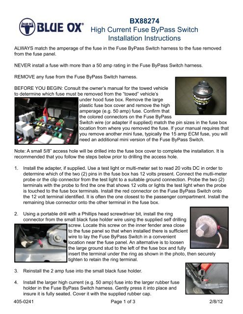
ALWAYS match the amperage of the fuse in the <strong>Fuse</strong> <strong>ByPass</strong> <strong>Switch</strong> harness to the fuse removed<br />
from the fuse panel.<br />
NEVER install a fuse with more than a 50 amp rating in the <strong>Fuse</strong> <strong>ByPass</strong> <strong>Switch</strong> harness.<br />
REMOVE any fuse from the <strong>Fuse</strong> <strong>ByPass</strong> <strong>Switch</strong> harness.<br />
BEFORE YOU BEGIN: Consult the owner’s manual for the towed vehicle<br />
to determine which fuse must be removed from the “towed” vehicle’s<br />
under hood fuse box. Remove the large<br />
plastic fuse box cover and remove the high<br />
amperage (e.g. 50 amp) fuse. Confirm that<br />
the colored connectors on the <strong>Fuse</strong> <strong>ByPass</strong><br />
<strong>Switch</strong> wire (or adapter if supplied) match the pin sizes in the fuse box<br />
location from where you removed the fuse. If your manual requires that<br />
you remove another mini fuse, typically the 15 amp ECM fuse, you will<br />
need an additional mini version of the <strong>Fuse</strong> <strong>ByPass</strong> <strong>Switch</strong>.<br />
Note: A small 5/8” access hole will be drilled into the fuse box cover to complete the installation. It is<br />
recommended that you follow the steps below prior to drilling the access hole.<br />
1. Install the adapter, if supplied. Use a test light or multi-meter set to read 20 volts DC in order to<br />
determine which of the two (2) pins in the fuse box has 12 volts present. Connect the mutli-meter<br />
probe or the clip connector from the test light to a suitable ground connection. Probe the two (2)<br />
terminals with the probe to find the one that shows 12 volts or lights the test light when the probe<br />
is touched to the fuse box terminals. Install the red connector on the <strong>Fuse</strong> <strong>ByPass</strong> <strong>Switch</strong> onto<br />
the 12 volt terminal identified. It is often the one closest to the passenger compartment. Install the<br />
remaining blue connector onto the other terminal in the fuse box.<br />
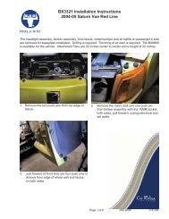
2. Using a portable drill with a Phillips head screwdriver bit, install the ring<br />
connector from the small black fuse holder wire using the supplied self drilling<br />
screw. Locate this screw on the inner fender area close<br />
to the fuse panel so that when installed there is sufficient<br />
wire to lay the <strong>Fuse</strong> <strong>ByPass</strong> <strong>Switch</strong> in a convenient<br />
location near the fuse panel. An alternative is to loosen<br />
the large ground stud to the left of the fuse box and fully<br />
insert the terminal under the ring as shown in the photo, then securely<br />
tighten to retain the ring terminal.<br />
3. Reinstall the 2 amp fuse into the small black fuse holder.<br />
4. Install the larger high current (e.g. 50 amp) fuse into the larger rubber fuse<br />
holder in the <strong>Fuse</strong> <strong>ByPass</strong> <strong>Switch</strong> harness. Gently press it into place and<br />
insure it is fully seated. Cover it with the supplied rubber cap.<br />
405-0241 Page 1 of 3 2/8/12
<strong>BX88274</strong><br />
<strong>High</strong> <strong>Current</strong> <strong>Fuse</strong> <strong>ByPass</strong> <strong>Switch</strong><br />
<strong>Installation</strong> Instructions<br />
Test the <strong>Fuse</strong> <strong>ByPass</strong> <strong>Switch</strong> by checking that when the button on the top of the <strong>Fuse</strong> <strong>ByPass</strong> <strong>Switch</strong><br />
is in the drive position that the car dash lights and functions operate the same as they did before.<br />
With the car engine and key turned fully off, flip the <strong>Fuse</strong> <strong>ByPass</strong> <strong>Switch</strong> to<br />
the tow position.<br />
All lights and operations that are controlled by the fuse in this circuit should<br />
be off. This mimics the fuse being removed from the fuse panel when towing.<br />
If the <strong>Fuse</strong> <strong>ByPass</strong> <strong>Switch</strong> operates as expected, continue, if not, please<br />
reference the Troubleshooting section.<br />
5. Remove the <strong>Fuse</strong> <strong>ByPass</strong> <strong>Switch</strong> connectors and adapter if supplied, from the fuse box. Note<br />
which terminal the red connector was installed in.<br />
6. Select one of the methods below to route the wiring out of the fuse panel.<br />
Method A<br />
a. Measure from the end of the fuse panel to the center over the<br />
removed fuse terminals. Write down the dimensions.<br />
b. Measure from the side of the fuse panel to the same location over<br />
the removed fuse terminals and write down the dimension.<br />
c. Properly orient the fuse panel cover over the fuse panel and mark<br />
the two dimensions on the cover of the fuse panel.<br />
d. Drill a 5/8” hole at the intersection of these dimensions use a flat power auger.<br />
Method B<br />
a. Alternatively drill a 5/8” hole at the top, left corner of the cover using a flat power auger.<br />
7. Feed the <strong>Fuse</strong> <strong>ByPass</strong> <strong>Switch</strong> terminals through the hole insuring<br />
that the black loom extends from the hole.<br />
8. Reinstall the connectors and replace the cover making sure it<br />
locks on using the plastic tabs.<br />
9. If a Mini <strong>Fuse</strong> <strong>ByPass</strong> <strong>Switch</strong> must be installed, it should be<br />
located at the lower, center of the top cover. Reference the dotted lines in the images shown<br />
above.<br />
Note: this requires a 3/4” hole and the drive position has the white dot side of the switch<br />
depressed when driving the vehicle and the tow position has the black (unmarked side)<br />
depressed when towing. This is opposite of the <strong>High</strong> <strong>Current</strong> <strong>Fuse</strong> <strong>ByPass</strong> <strong>Switch</strong>. Install the<br />
labels supplied with the white dot on the switch matched to the drive label.<br />
405-0241 Page 2 of 3 2/8/12
<strong>BX88274</strong><br />
<strong>High</strong> <strong>Current</strong> <strong>Fuse</strong> <strong>ByPass</strong> <strong>Switch</strong><br />
<strong>Installation</strong> Instructions<br />
10. Find a suitable location next to the fuse box to move the <strong>Fuse</strong> <strong>ByPass</strong> <strong>Switch</strong> using the hook and<br />
loop material supplied. Wipe the side of the <strong>Fuse</strong> <strong>ByPass</strong> <strong>Switch</strong> with an alcohol swap and clean<br />
the mounting area well.<br />
11. A small amount of silicone seal, not supplied, may be placed around the loom hole to reduce the<br />
chance of water entering the fuse box.<br />
If the <strong>Fuse</strong> <strong>ByPass</strong> <strong>Switch</strong> fails to operate:<br />
TROUBLESHOOTING<br />
• Be sure you have the correct fuse to remove in the towed vehicle’s fuse box<br />
• Verify the connectors are fully seated in the correct position and properly connected to the<br />
adapter, if supplied, in the fuse panel and that they are not touching each other. If they are<br />
reversed the <strong>Fuse</strong> <strong>ByPass</strong> <strong>Switch</strong> will not function<br />
• Make sure the correct fuse is correctly installed in each fuse holder that neither fuse is blown<br />
• Check to see if the small black wire is properly grounded to the vehicle body<br />
CUSTOMER SERVICE COMMITMENT<br />
<strong>Blue</strong> <strong>Ox</strong>® is committed to providing you with exceptional customer care throughout your lifetime<br />
with our products. Our team is here to assist you with any questions you may have regarding the<br />
performance of your product. Simply call (402) 385-3051 and you can speak with our customer care<br />
team.<br />
Additionally, please visit our website to see which rallies our Destination America team will be<br />
attending. For a nominal fee, our service technician will service your towing system to ensure it’s in<br />
proper working condition. Also, as a commitment to our customers, should you visit our factory, you<br />
can stay at our full service <strong>Blue</strong> <strong>Ox</strong>® campground at no charge along with enjoying a factory tour.<br />
Again, thank you for being our customer and for the confidence you have shown in the performance<br />
of our products. It is because of customers like you we enjoy the success we have today.<br />
© 2012 <strong>Blue</strong> <strong>Ox</strong><br />
One Mill Road, Industrial Park<br />
Pender, Nebraska 68047<br />
Phone: (402) 385-3051<br />
Fax: (402) 385-3360<br />
www.blueox.com<br />
405-0241 Page 3 of 3 2/8/12