ELECTRO-MECH SCOREBOARD CO. MP-375 ... - Scoreboards
ELECTRO-MECH SCOREBOARD CO. MP-375 ... - Scoreboards
ELECTRO-MECH SCOREBOARD CO. MP-375 ... - Scoreboards

Create successful ePaper yourself
Turn your PDF publications into a flip-book with our unique Google optimized e-Paper software.
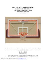
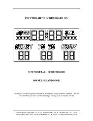
<strong>ELECTRO</strong>-<strong>MECH</strong> <strong>S<strong>CO</strong>REBOARD</strong> <strong>CO</strong>.<br />
<strong>MP</strong>-<strong>375</strong> FOOTBALL <strong>S<strong>CO</strong>REBOARD</strong><br />
OWNER’S HANDBOOK<br />
Thank you for choosing an Electro-Mech Scoreboard for your athletic complex. We are<br />
confident that your new scoreboard will give many years of reliable service.<br />
Electro-Mech Scoreboard Co. • #3 Industrial Parkway • Wrightsville, GA 31096<br />
Phone: (800) 445-7846 • Fax (912) 864-0212 • Email: score@electro-mech.com
Model <strong>MP</strong>-<strong>375</strong> Page 2<br />
TABLE OF <strong>CO</strong>NTENTS<br />
<strong>MP</strong>-<strong>375</strong> FOOTBALL <strong>S<strong>CO</strong>REBOARD</strong> SPECIFICATIONS.....................................................3<br />
<strong>S<strong>CO</strong>REBOARD</strong> INSTALLATION..............................................................................................3<br />
POSITIONING THE POSTS...............................................................................................4<br />
MOUNTING HARDWARE ................................................................................................6<br />
MOUNTING THE OPTIONAL TOP SPONSOR PANEL .........................................7<br />
MOUNTING THE <strong>S<strong>CO</strong>REBOARD</strong> .................................................................................8<br />
ELECTRICAL <strong>CO</strong>NNECTIONS.......................................................................................9<br />
Ground Connection ...............................................................................................................9<br />
Connecting The Scoreboard To Your Power Source .........................................................9<br />
Installing The Horn .............................................................................................................12<br />
ScoreLink 300.......................................................................................................................17<br />
Installing The Control Cable ..............................................................................................17<br />
Connecting The Control Console .......................................................................................18<br />
<strong>S<strong>CO</strong>REBOARD</strong> OPERATION ..................................................................................................19<br />
HAND HELD CLOCK <strong>CO</strong>NTROL UNIT OPERATION ........................................23<br />
SERVICING THE <strong>S<strong>CO</strong>REBOARD</strong> ..........................................................................................24<br />
PLUG IN MODULE REPLACEMENT .........................................................................26<br />
LA<strong>MP</strong> REPLACEMENT ...................................................................................................27<br />
WARRANTY................................................................................................................................28<br />
Electro-Mech Scoreboard Co. • #3 Industrial Parkway • Wrightsville, GA 31096<br />
Phone: (800) 445-7846 • Fax (912) 864-0212 • Email: score@electro-mech.com
Model <strong>MP</strong>-<strong>375</strong> Page 3<br />
<strong>MP</strong>-<strong>375</strong> FOOTBALL <strong>S<strong>CO</strong>REBOARD</strong> SPECIFICATIONS<br />
GENERAL: This ETL listed scoreboard includes the scoreboard cabinet, mounting hardware, control<br />
console, control cable (sold separately), 10 ft. extension cable, and junction box.<br />
DIMENSIONS: <strong>MP</strong>-<strong>375</strong>: 32’ L x 10’ H x 6” D (two sections which measure 32’ L x 5’ H x 6” D),<br />
optional top sponsor panel: 32’ L x 33” H x 6” D (two sections which measure 16’ L x 33” H x 6”<br />
D)<br />
WEIGHT: <strong>MP</strong>-<strong>375</strong>: 900 lbs (The top section weighs 480 lbs, the bottom section weighs 420 lbs), optional<br />
top sponsor panel: 240 lbs (two sections which weigh 120 lbs each)<br />
<strong>S<strong>CO</strong>REBOARD</strong> <strong>CO</strong>NSTRUCTION: The scoreboard consists of two aluminum sections. The outer<br />
frame is made from extruded aluminum. Internal structural parts may be extruded or formed from<br />
aluminum sheet. The face and back are made from aluminum sheet. The face is finished with<br />
enamel paint. Black is the standard face color. White is the standard color for the captions.<br />
Mounting hardware is included.<br />
DISPLAY: The <strong>MP</strong>-<strong>375</strong> FOOTBALL scoreboard displays HOME and VISITOR scores to 99, TIME to 99<br />
minutes, BALL ON, YDS. TO GO, DOWN, QTR, TIME-OUTS, and Possession indicators.<br />
LA<strong>MP</strong> BANKS: A 4 x 7 matrix of lamps forms each 24” digit. Each possession indicator is formed in<br />
the shape of a football. The scoreboard uses 15 watt 120 VAC frosted medium based appliance<br />
lamps (also known as 15A15IF lamps). Recessed aluminum reflectors provide a crisp separation<br />
between each lamp. Expanded metal screens protect the lamps.<br />
POWER REQUIREMENTS: Scoreboard - 120 VAC, 42.5 A, 60 Hz, 5100 watts maximum, (60 A<br />
service recommended). The scoreboard may be connected to either 120 VAC or 240 VAC single<br />
phase. Control Console - 120 VAC, 0.5 A, 60 Hz<br />
<strong>S<strong>CO</strong>REBOARD</strong> <strong>ELECTRO</strong>NICS: 100% solid state fully enclosed within 4 plug in modules.<br />
<strong>CO</strong>NTROL <strong>CO</strong>NSOLE: The microprocessor control console is constructed of a rugged plastic housing<br />
with a metal back plate. It features a 37 key sealed membrane keypad, a LCD display of game<br />
information, an attached 6 foot power cord, and a lithium cell battery backup to retain game<br />
information.<br />
<strong>CO</strong>NTROL CABLE: The cable has two 22 AWG stranded copper conductors with semi-rigid PVC<br />
insulation. It also has a braided shield and a foil shield. The polyethylene jacket is rated at 300<br />
volts. The cable is direct burial rated and measures approximately ¼” in diameter. One length is<br />
required to run from the scoreboard to the point of operation (conduit installation recommended).<br />
JUNCTION BOX AND EXTENSION CABLE: A 4 ¼” x 2 ¼” x 2” junction box with a stereo jack<br />
mounted on the face is attached to the control cable at the point of operation. A ten foot extension<br />
cable connects the control console to the junction box.<br />
WARRANTY: Five year limited warranty.<br />
Electro-Mech Scoreboard Co. • #3 Industrial Parkway • Wrightsville, GA 31096<br />
Phone: (800) 445-7846 • Fax (912) 864-0212 • Email: score@electro-mech.com
Model <strong>MP</strong>-<strong>375</strong> Page 4<br />
<strong>S<strong>CO</strong>REBOARD</strong> INSTALLATION<br />
Installation of the <strong>MP</strong>-<strong>375</strong> Scoreboard consists of positioning the posts, mounting the<br />
scoreboard cabinet on the posts, and making the proper electrical connections.<br />
Items not provided by Electro-Mech Scoreboard Company which are necessary for<br />
installation:<br />
• Four posts<br />
• Power cable to connect the scoreboard to your power source<br />
• Grounding hardware<br />
• A grounded NEMA 5-15R 120 VAC receptacle for the control console.<br />
Items not provided which are recommended by Electro-Mech Scoreboard Company for<br />
installation:<br />
• A weatherproof power disconnect at the scoreboard<br />
• A weatherproof NEMA 5-15R 120 VAC convenience receptacle at the<br />
scoreboard<br />
While Electro-Mech Scoreboard Company does not perform installations, we will make<br />
every effort to answer your installation questions. Installation should be performed by<br />
qualified personnel. Consult national and local codes before installation.<br />
POSITIONING THE POSTS<br />
The scoreboard is designed to be mounted on four posts. We suggest that the front of the<br />
scoreboard should angled away from the afternoon sun, if possible. Typically installers<br />
will use steel pipes or I-beams. The mounting hardware will accommodate posts up to 7<br />
inches outer diameter. We recommend that the posts are sunk in reinforced concrete<br />
footings. Figure 1 shows the spacing of the posts for a <strong>MP</strong>-<strong>375</strong>. It suggests one possible<br />
installation for a <strong>MP</strong>-<strong>375</strong> in silty sand soil. No dimensional data in this manual is<br />
intended to be specifications except the size of the scoreboard cabinet and the<br />
distance between the posts. The specifications for the posts and concrete footings are<br />
dependent upon the expected local wind and soil conditions, the height of the scoreboard<br />
from the ground, and the local building codes. Electro-Mech Scoreboard Company<br />
assumes no responsibility for the installation of scoreboards by others.<br />
Electro-Mech Scoreboard Co. • #3 Industrial Parkway • Wrightsville, GA 31096<br />
Phone: (800) 445-7846 • Fax (912) 864-0212 • Email: score@electro-mech.com
Model <strong>MP</strong>-<strong>375</strong> Page 5<br />
Earth Ground<br />
120 VAC Convenience<br />
Receptacle<br />
Power Disconnect<br />
Power Cable in<br />
3/4" Conduit<br />
To Power<br />
Supply<br />
Control Cable in<br />
3/4" Conduit<br />
To Control<br />
Center<br />
Figure 1 <strong>MP</strong>-<strong>375</strong> Post Spacing<br />
Figure 2 shows the spacing of the posts for a <strong>MP</strong>-<strong>375</strong> with an optional top sponsor panel.<br />
Earth Ground<br />
120 VAC Convenience<br />
Receptacle<br />
Power Disconnect<br />
Power Cable in<br />
3/4" Conduit<br />
To Power<br />
Supply<br />
Control Cable in<br />
3/4" Conduit<br />
To Control<br />
Center<br />
Figure 2 <strong>MP</strong>-<strong>375</strong> with Optional Top Sponsor Panel Post Spacing<br />
Electro-Mech Scoreboard Co. • #3 Industrial Parkway • Wrightsville, GA 31096<br />
Phone: (800) 445-7846 • Fax (912) 864-0212 • Email: score@electro-mech.com
Model <strong>MP</strong>-<strong>375</strong> Page 6<br />
MOUNTING HARDWARE<br />
Eight sets of mounting hardware are provided to attach the scoreboard to the posts.<br />
Additional hardware sets are provided to attach the optional sponsor panels, if ordered. A<br />
mounting hardware set consists of a steel angle bracket, two threaded rods, two washers,<br />
and two nuts. Figure 3 shows an overhead cross section view and a side cross section<br />
view of the scoreboard attached to a post at a mounting point using the hardware. A steel<br />
bracket is riveted to the scoreboard’s aluminum extrusion frame. The bracket has two<br />
tapped holes. The threaded rods screw into these tapped holes. The washers and nuts are<br />
used to clamp the steel angle bracket against the steel post and hold the scoreboard in<br />
place.<br />
Electro-Mech Scoreboard Co. • #3 Industrial Parkway • Wrightsville, GA 31096<br />
Phone: (800) 445-7846 • Fax (912) 864-0212 • Email: score@electro-mech.com
Model <strong>MP</strong>-<strong>375</strong> Page 7<br />
Overhead cross section view<br />
Side cross section view<br />
Steel Angle Bracket<br />
Steel Angle Bracket<br />
Figure 3 Standard Mounting Method<br />
MOUNTING THE OPTIONAL TOP SPONSOR PANEL<br />
The following steps describe how to mount the top sponsor panel on the posts:<br />
1. Place the top sponsor panel against the posts on the ground. Make sure the mounting<br />
points are aligned with the posts.<br />
2. Screw the threaded rods into the tapped holes in the top sponsor panel.<br />
3. Place a steel angle bracket over the threaded rods at a mounting point.<br />
4. Place a washer over each threaded rod.<br />
5. Screw the nuts onto the threaded rods so that the bracket is loosely held in place.<br />
6. Repeat steps 4 -6 at the other mounting points.<br />
7. Raise the top sponsor panel into place and tighten the nuts to clamp it in place on the<br />
posts.<br />
Electro-Mech Scoreboard Co. • #3 Industrial Parkway • Wrightsville, GA 31096<br />
Phone: (800) 445-7846 • Fax (912) 864-0212 • Email: score@electro-mech.com
Model <strong>MP</strong>-<strong>375</strong> Page 8<br />
MOUNTING THE <strong>S<strong>CO</strong>REBOARD</strong><br />
Each section of the scoreboard is attached to the posts at four points. Figure 4 shows the<br />
location of the mounting points on the rear of the scoreboard.<br />
MOUNTING POINTS<br />
MOUNTING POINTS<br />
Figure 4 Mounting Points<br />
The following steps describe how to mount the scoreboard on the posts:<br />
1. Place the upper section of the scoreboard against the posts on the ground. Make sure<br />
the mounting points are aligned with the posts.<br />
2. Screw the threaded rods into the tapped holes in the scoreboard.<br />
3. Place a steel angle bracket over the threaded rods at a mounting point.<br />
4. Place a washer over each threaded rod.<br />
5. Screw the nuts onto the threaded rods so that the bracket is loosely held in place.<br />
6. Repeat steps 4 -6 at the other mounting points.<br />
7. Raise the section into place and tighten the nuts to clamp it in place on the posts.<br />
8. Place the lower section of the scoreboard against the posts on the ground. Make sure<br />
the mounting points are aligned with the posts.<br />
9. Attach the mounting hardware by the same method as the upper section.<br />
10. Raise the lower section to a few inches below the top section.<br />
11. There is a cable with a 15 pin plug which is accessible through an opening in the top<br />
of the lower section frame. Plug this cable into the 15 pin socket which is accessible<br />
through an opening in the bottom of the top section frame.<br />
12. Raise the lower section to the bottom of the upper section and tighten the nuts to<br />
clamp it in place on the posts.<br />
Electro-Mech Scoreboard Co. • #3 Industrial Parkway • Wrightsville, GA 31096<br />
Phone: (800) 445-7846 • Fax (912) 864-0212 • Email: score@electro-mech.com
Model <strong>MP</strong>-<strong>375</strong> Page 9<br />
ELECTRICAL <strong>CO</strong>NNECTIONS<br />
We recommend a qualified electrician perform the needed electrical connections to<br />
ensure proper operation of your scoreboard. These connections include grounding the<br />
scoreboard, connecting the scoreboard to a power source, installing the horn, installing<br />
the control cable, and connecting the control console.<br />
Ground Connection<br />
The National Electrical Code requires a scoreboard (electric sign) to be grounded.<br />
Grounding the scoreboard helps the scoreboard electronics operate properly and helps<br />
minimize damage if it is struck by lightning. Metal posts do not provide an adequate<br />
ground path when they are placed in concrete. One method of grounding is to connect<br />
both sections of the scoreboard to one or more grounding rods which are driven into the<br />
ground near the scoreboard via a large gauge copper wire. The self tapping sheet metal<br />
screws on the back of the scoreboard cabinet provide a convenient connection point.<br />
Connecting The Scoreboard To Your Power Source<br />
The scoreboard may be connected to 240 VAC single phase or 120 VAC service at the<br />
scoreboard. Maximum power consumption of Model <strong>MP</strong>-<strong>375</strong>: 5100 Watts. Make<br />
sure that the power cables are rated for this electrical load. Electro-Mech Scoreboard<br />
Company recommends that your power cable is installed in conduit. Avoid running your<br />
power cables in close proximity to your control cable. The following steps describe how<br />
to connect the scoreboard to your power source:<br />
1. Remove the hex head screws which hold the upper section rear access panel in place<br />
(Figure 5).<br />
Rear Access Panel<br />
knockouts<br />
Figure 5 Upper Section Rear Access Panel<br />
Electro-Mech Scoreboard Co. • #3 Industrial Parkway • Wrightsville, GA 31096<br />
Phone: (800) 445-7846 • Fax (912) 864-0212 • Email: score@electro-mech.com
Model <strong>MP</strong>-<strong>375</strong> Page 10<br />
Figure 6 shows the view behind the access panel.<br />
MTO-01<br />
MSF-01<br />
MC-01<br />
T1<br />
S12<br />
8A 8A 5A 1/2A<br />
F1 F2 F3 F4<br />
8A 8 A 3A 8A<br />
F5 F6 F7 F8<br />
5 A<br />
F9<br />
T2 T3 T4<br />
Figure 6 Upper Access Panel Removed<br />
2. Punch out the knockouts for the power and control cables.<br />
3. Feed the power cables through a knockout.<br />
4. If you are going to connect the scoreboard to a 240 VAC supply, connect one AC line<br />
wire to position 2, AC neutral wire to position 3, and the other AC line wire to<br />
position 4 of terminal strip T4 on the junction chassis according to figure 7.<br />
Electro-Mech Scoreboard Co. • #3 Industrial Parkway • Wrightsville, GA 31096<br />
Phone: (800) 445-7846 • Fax (912) 864-0212 • Email: score@electro-mech.com
Model <strong>MP</strong>-<strong>375</strong> Page 11<br />
Factory installed<br />
jumper from position<br />
1 to position 2<br />
Factory installed<br />
jumper from position<br />
4 to position 5<br />
Position 4:<br />
AC line (hot)<br />
wire from your<br />
power source<br />
Position 2:<br />
AC line (hot) wire<br />
from your power<br />
Position 3:<br />
AC neutral wire<br />
from your power<br />
source<br />
Figure 7 240 VAC Connections<br />
5. If you are going to connect the scoreboard to a 120 VAC supply, connect the AC line<br />
wire to position 2 and the AC neutral wire to position 3 of terminal strip T3 on the<br />
junction chassis. Add a jumper from position 2 to position 4. This jumper is not<br />
provided. Refer to figure 8.<br />
Factory Installed<br />
jumper from position<br />
1 to position 2<br />
Factory installed<br />
jumper from position<br />
4 to position 5<br />
Jumper from position 2<br />
to position 4 (NOT<br />
PROVIDED)<br />
Position 2:<br />
AC line (hot) wire<br />
from your power<br />
Position 3:<br />
AC neutral wire<br />
from your power<br />
source<br />
Figure 8 120 VAC Connections<br />
Electro-Mech Scoreboard Co. • #3 Industrial Parkway • Wrightsville, GA 31096<br />
Phone: (800) 445-7846 • Fax (912) 864-0212 • Email: score@electro-mech.com
Model <strong>MP</strong>-<strong>375</strong> Page 12<br />
Electro-Mech Scoreboard Company suggests that you install a power cut-off switch and a<br />
NEMA 5-15R receptacle in a weatherproof box on the scoreboard post below the<br />
scoreboard. The cut-off switch provides a convenient way of turning the scoreboard off<br />
during maintenance or repairs. The NEMA 5-15R receptacle will allow a technician to<br />
easily plug in the control console and operate the scoreboard via the test jack S-12 (a<br />
valuable trouble-shooting aid).<br />
Installing The Horn<br />
The items provided to install the horn are the horn, the weatherproof back box, the<br />
mounting bolt, and the mounting bracket. Items which are not provided but are necessary<br />
for proper installation are ¾” flexible conduit, a ¾” right angle male conduit connector, a<br />
¾” straight male conduit connector, two wires, and four forked crimp terminals. The<br />
electrical requirements for the horn are 0.35 A 120 VAC. The horn is normally mounted<br />
to the top of the <strong>MP</strong>-<strong>375</strong>. The horn may be mounted on the side if the scoreboard has a<br />
top sponsor panel. A tapped hole is provided to fasten the horn to the scoreboard. The<br />
mounting bolt is screwed into the tapped hole at the factory. The following steps describe<br />
the assembly and mounting of the horn:<br />
1. Cut a piece of ¾” conduit of sufficient length to reach from the horn mounting point<br />
to one of the knockouts below the upper access panel.<br />
2. Attach the ¾” right angle male conduit connector to one end of the conduit and the<br />
¾” straight male conduit connector to the other end.<br />
3. Cut two pieces of wire of approximately 7 feet longer than the conduit.<br />
4. Push the wires through the conduit.<br />
5. Push the end of the conduit with the right angle male conduit connector through the<br />
2” diameter hole in mounting bracket as seen in figure 9.<br />
Electro-Mech Scoreboard Co. • #3 Industrial Parkway • Wrightsville, GA 31096<br />
Phone: (800) 445-7846 • Fax (912) 864-0212 • Email: score@electro-mech.com
Model <strong>MP</strong>-<strong>375</strong> Page 13<br />
Figure 9 Horn Mounting Bracket<br />
6. The weatherproof back box has two threaded conduit holes. Screw the provided<br />
conduit plug into the hole near the word “TOP” inside the weatherproof back box<br />
(figure 10).<br />
Electro-Mech Scoreboard Co. • #3 Industrial Parkway • Wrightsville, GA 31096<br />
Phone: (800) 445-7846 • Fax (912) 864-0212 • Email: score@electro-mech.com
Model <strong>MP</strong>-<strong>375</strong> Page 14<br />
Insert conduit plug here.<br />
Figure 10 Horn Back Box<br />
7. Feed the wires through the other back box conduit hole and screw the right angle<br />
conduit connector to the back box.<br />
8. Attach the weatherproof back box to the mounting bracket using the provided 6-32 x<br />
5/8” screws and 6-32 gold nuts as shown in figure 11.<br />
Electro-Mech Scoreboard Co. • #3 Industrial Parkway • Wrightsville, GA 31096<br />
Phone: (800) 445-7846 • Fax (912) 864-0212 • Email: score@electro-mech.com
Model <strong>MP</strong>-<strong>375</strong> Page 15<br />
BACK BOX<br />
MOUNTING POINTS<br />
MOUNTING BRACKET<br />
MOUNTING HOLE<br />
BACK BOX BOSSES<br />
Figure 11 Back Box Mounting Points<br />
9. Remove the horn signal mounting plate from the horn base by loosening the phillips<br />
head screw on the base.<br />
10. The word “TOP” is stamped on the front side of the horn signal mounting plate. Pass<br />
the two wires that are inside the back box through the horn signal mounting plate<br />
center hole from the back side.<br />
11. Align the holes in the horn signal mounting plate with the mounting screw holes in<br />
the back box bosses. The word “TOP” on the horn signal mounting plate and the<br />
back box should be oriented in the same direction and the screw hole on the bottom<br />
edge of the horn signal mounting plate should be directly over the gap in the back box<br />
gasket as seen in figure 12.<br />
Electro-Mech Scoreboard Co. • #3 Industrial Parkway • Wrightsville, GA 31096<br />
Phone: (800) 445-7846 • Fax (912) 864-0212 • Email: score@electro-mech.com
Model <strong>MP</strong>-<strong>375</strong> Page 16<br />
Plug Receptacle<br />
Screw Hole<br />
Figure 12 Mounting Bracket with Back Box and Signal Mounting Plate Attached<br />
12. Fasten the horn signal mounting plate with the four 8-32 x 7/16” machine screws that<br />
are provided with the back box.<br />
13. Crimp forked terminals on the ends of the two wires and attach them to the plug<br />
receptacle.<br />
14. Slide the slot on the side of the horn base over the tab on the horn signal mounting<br />
plate and tighten the phillips head screw on the other side of the horn base.<br />
15. Fasten the horn assembly to the scoreboard using the mounting bolt from the<br />
scoreboard.<br />
16. Crimp forked terminals on the ends of the two wires that protrude out of the other end<br />
of the conduit.<br />
17. Pass the wires through one of the knockouts below the upper access panel.<br />
18. Fasten the conduit connector to the knockout panel and connect the wires to T-2.<br />
Electro-Mech Scoreboard Co. • #3 Industrial Parkway • Wrightsville, GA 31096<br />
Phone: (800) 445-7846 • Fax (912) 864-0212 • Email: score@electro-mech.com
Model <strong>MP</strong>-<strong>375</strong> Page 17<br />
ScoreLink 300<br />
The S<strong>CO</strong>RELINK 300 RF MODEM SET is intended to eliminate the control cable<br />
between the scoreboard and the control console on Electro-Mech Scoreboard MM and<br />
<strong>MP</strong> series scoreboards. If you have purchased this option, disregard the next section of<br />
this manual. Refer to the S<strong>CO</strong>RELINK 300 RF MODEM SET OWNER’S<br />
HANDBOOK for installation instructions.<br />
Installing The Control Cable<br />
The control cable connects the scoreboard to the control console. While the control cable<br />
is direct burial rated, Electro-Mech Scoreboard Company recommends that it is installed<br />
in conduit to protect it from being cut. A small junction box with a stereo jack mounted<br />
on the face plate is attached to the control cable at the point of operation of the<br />
scoreboard. This junction box should be securely mounted in a clean, dry area within ten<br />
feet of the rear of the control console. Most customers order the control cable with the<br />
junction box attached. Some customers prefer to attach the junction box after the cable is<br />
installed. Those customers must match their stereo jack to one of the stereo jacks in<br />
figure 13 in order to make the proper connections. These connections should be soldered.<br />
STEREN<br />
1/4" STEREO JACK<br />
SWITCHCRAFT<br />
1/4" STEREO JACK<br />
ORANGE<br />
TAN<br />
1<br />
3 2<br />
PIN 1 - BLACK WIRE<br />
PIN 2 - RED WIRE<br />
PIN 3 - SHIELD, GREEN WIRE<br />
2 3<br />
1<br />
Figure 13 STEREO JACK WIRING DIAGRAM<br />
The following steps describe how to connect the control cable to the scoreboard:<br />
1. At the rear of the scoreboard feed the control cable through one of the knockouts<br />
below the upper access panel.<br />
2. Crimp fork terminals to the control cable wires and the shield.<br />
3. Connect the control cable to terminal strip T1 (located to the left of the test jack S12)<br />
according to the diagram in figure 14.<br />
Electro-Mech Scoreboard Co. • #3 Industrial Parkway • Wrightsville, GA 31096<br />
Phone: (800) 445-7846 • Fax (912) 864-0212 • Email: score@electro-mech.com
Model <strong>MP</strong>-<strong>375</strong> Page 18<br />
BLACK RED SHIELD<br />
Figure 14 T1 WIRING DIAGRAM<br />
Connecting The Control Console<br />
The control console is normally connected to the junction box via the 10 ft. extension<br />
cable. This extra length of cable allows the scoreboard operator some mobility and the<br />
ability to store the control console after the game. The extension cable has two molded<br />
stereo plugs attached to it. One end of the extension cable is plugged into the junction<br />
box stereo jack and the other end is plugged into the stereo jack mounted on the control<br />
console back plate. The control console power cord is plugged into a grounded NEMA 5-<br />
15R 120 VAC receptacle.<br />
Electro-Mech Scoreboard Co. • #3 Industrial Parkway • Wrightsville, GA 31096<br />
Phone: (800) 445-7846 • Fax (912) 864-0212 • Email: score@electro-mech.com
Model <strong>MP</strong>-<strong>375</strong> Page 19<br />
<strong>S<strong>CO</strong>REBOARD</strong> OPERATION<br />
The <strong>MP</strong>-<strong>375</strong> Scoreboard is operated by the control console. No scoreboard functions<br />
will operate without connecting the control console. Figure 15 shows the keypad<br />
layout on your control console. The keypad functions are described in the text below the<br />
figure.<br />
<strong>ELECTRO</strong>-<strong>MECH</strong> <strong>S<strong>CO</strong>REBOARD</strong> <strong>CO</strong>.<br />
P.O. BOX 102 #3 INDUSTRIAL PARKWAY<br />
WRIGHTSVILLE, GA 31096<br />
(912) 864-3366<br />
SET<br />
CLOCK<br />
SET<br />
CLOCK<br />
.1 SEC<br />
.1 SEC<br />
ON/<br />
OFF<br />
CLOCK<br />
UP/<br />
DOWN<br />
FOOTBALL/SOCCER/TRACK<br />
DELAY<br />
OF GAME<br />
TIMER<br />
AUTO<br />
HORN<br />
TIME<br />
OF<br />
DAY<br />
TIME<br />
OUT<br />
TIMER<br />
7 8 9<br />
DIMMER<br />
SET<br />
GUEST<br />
S<strong>CO</strong>RE<br />
SET<br />
HOME<br />
S<strong>CO</strong>RE<br />
YARDS<br />
TO GO<br />
BALL<br />
ON<br />
4 5 6<br />
NEW<br />
GAME<br />
1 2 3<br />
GUEST<br />
TIME<br />
OUTS<br />
HOME<br />
TIME<br />
OUTS<br />
DOWN<br />
CLEAR 0 ENTER QTR<br />
GUEST<br />
S<strong>CO</strong>RE<br />
+1<br />
HOME<br />
S<strong>CO</strong>RE<br />
+1<br />
NEXT<br />
POSS<br />
HORN<br />
ON/<br />
OFF<br />
CLOCK<br />
ON/<br />
OFF<br />
Figure 15 Keypad Layout<br />
Control Console Key Functions<br />
1. SET CLOCK – This key sets the time displayed on the scoreboard clock. Press<br />
[SET CLOCK], the keypad numbers for the time, [ENTER]. Example: Press [SET<br />
CLOCK], [6], [0], [0], [0], [ENTER] on the control console. 60:00 will be displayed<br />
on the clock section of the scoreboard.<br />
Electro-Mech Scoreboard Co. • #3 Industrial Parkway • Wrightsville, GA 31096<br />
Phone: (800) 445-7846 • Fax (912) 864-0212 • Email: score@electro-mech.com
Model <strong>MP</strong>-<strong>375</strong> Page 20<br />
2. SET CLOCK .1 SEC – This key is used when the clock is in the 1/10 th second mode.<br />
Press [SET CLOCK .1 SEC], the keypad numbers for the time, [ENTER]. Example:<br />
Press [SET CLOCK .1 SEC], [5], [3], [8], [ENTER] on the control console. 53.8 will<br />
be displayed on the clock section of the scoreboard.<br />
3. .1 SEC ON OFF – This key is used to enable or disable the 1/10 th second mode on<br />
the scoreboard. This mode is enabled when the control console is turned on. If it is<br />
disabled, the LCD display on the control console will still show 1/10 th second timing,<br />
but the scoreboard will not display it. To turn this function off, press [.1 SEC<br />
ON/OFF]. The console LCD display will read:<br />
CLOCK ON - 1<br />
.1 SEC OFF - 0<br />
Press [0], [ENTER] on the control console.<br />
4. CLOCK UP / DOWN – The clock can be set up to either count up or count down.<br />
The control console will reset to the clock down mode when it is turned on. To make<br />
the clock count up, press [CLOCK UP / DOWN]. The console LCD display will<br />
read:<br />
GAME UP - 1<br />
CLOCK DOWN - 0<br />
Press [0], [ENTER] on the control console. To reset the clock to count down mode,<br />
press [CLOCK UP / DOWN], [1], [ENTER] on the control console.<br />
5. DELAY OF GAME TIMER – The delay of game timer should be set prior to the<br />
start of a game. The game timer default time is 30 seconds. To change this time,<br />
press [DELAY OF GAME TIMER]. The console LCD display will read:<br />
DELAY TIME1 <br />
Press the keypad numbers for the time, [ENTER]. The LCD display will then read:<br />
DELAY TIME2 <br />
This will allow you to change the second reset time. To change this time, press the<br />
keypad numbers for the time, [ENTER].<br />
Electro-Mech Scoreboard Co. • #3 Industrial Parkway • Wrightsville, GA 31096<br />
Phone: (800) 445-7846 • Fax (912) 864-0212 • Email: score@electro-mech.com
Model <strong>MP</strong>-<strong>375</strong> Page 21<br />
6. AUTO HORN – This key allows the operator to control the end of period horn and /<br />
or the time out horn. The horn normally sounds for two seconds when the clock<br />
reaches 0:00. The end of period horn can be disabled by pressing [AUTO HORN].<br />
The console LCD display will read:<br />
GAME PRESS ON<br />
HORN PRESS OFF<br />
Press [0], [ENTER] to disable the horn. The console LCD display will then read:<br />
T-O PRESS ON<br />
HORN PRESS OFF<br />
The time out horn is normally disabled. To enable the horn to sound at the end of the<br />
time out,press [1], [ENTER] on the control console.<br />
7. TIME OF DAY – The time of day can be displayed on the clock section of the<br />
scoreboard. THE GAME CLOCK WILL BE INOPERABLE UNTIL THE<br />
TIME OF DAY FUNCTION IS TURNED OFF. To turn the time of day clock on,<br />
press [TIME OF DAY]. The console LCD display will read:<br />
TIME OF ON <br />
DAY CLOCK OFF <br />
Press [1], [ENTER] on the control console. The console LCD display will then read:<br />
SET CLK <br />
Press the keypad numbers for the time, [ENTER]. The scoreboard will display the<br />
time of day.<br />
8. TIME OUT TIMER – To set the Time Out timer, press [TIME OUT TIMER]. The<br />
console LCD display will read:<br />
SET T-O <br />
Press the keypad numbers for the time, [ENTER]. The scoreboard will not display the<br />
Time Out time.<br />
9. SET GUEST S<strong>CO</strong>RE – To set the guest score, press [SET GUEST S<strong>CO</strong>RE], the<br />
keypad numbers for the time, [ENTER]. EXA<strong>MP</strong>LE: To set the guest score to 53,<br />
press [SET GUEST S<strong>CO</strong>RE], [5], [3], [ENTER].<br />
10. SET HOME S<strong>CO</strong>RE – To set the home score, press [SET HOME S<strong>CO</strong>RE], the<br />
keypad numbers for the time, [ENTER]. EXA<strong>MP</strong>LE: To set the home score to 75,<br />
press [SET HOME S<strong>CO</strong>RE], [7], [5], [ENTER].<br />
Electro-Mech Scoreboard Co. • #3 Industrial Parkway • Wrightsville, GA 31096<br />
Phone: (800) 445-7846 • Fax (912) 864-0212 • Email: score@electro-mech.com
Model <strong>MP</strong>-<strong>375</strong> Page 22<br />
11. YARDS TO GO – To set the yards to go, press [YARDS TO GO], the keypad<br />
numbers for the yards, [ENTER]. EXA<strong>MP</strong>LE: To set the yards to go to 10, press<br />
[YARDS TO GO], [1], [0], [ENTER].<br />
12. BALL ON – To display the position that the ball is located on the field, press [BALL<br />
ON], the keypad numbers for the yards, [ENTER]. EXA<strong>MP</strong>LE: To display that the<br />
ball is on the 35 yard line, press [BALL ON], [3], [5], [ENTER].<br />
13. GUEST TIME OUTS – This key decrements the Guest time outs by 1. Each team<br />
starts with four time outs. If this key is pressed when GUEST TIME OUTS displays<br />
0, it will change to 4.<br />
14. HOME TIME OUTS – This key decrements the HOME time outs by 1. Each team<br />
starts with four time outs. If this key is pressed when HOME TIME OUTS displays<br />
0, it will change to 4.<br />
15. DOWN – This key increments the DOWN by 1. If this key is pressed when DOWN<br />
displays 4, it will change to 0.<br />
16. GUEST S<strong>CO</strong>RE +1 – This key increments the Guest score by 1.<br />
17. HOME S<strong>CO</strong>RE +1 – This key increments the Home score by 1.<br />
18. NEXT POSS – This key toggles the possession indicators between Guest and Home.<br />
19. HORN ON/OFF – This key is used to sound the horn for ½ second.<br />
20. CLOCK ON/OFF – This key is used to start and stop the clock.<br />
21. QTR – This key increments the quarter indicator.<br />
22. NEW GAME – This key is used to reset all the scoreboard functions to their default<br />
settings. To reset the scoreboard, press [NEW GAME]. The console LCD display<br />
will read:<br />
RESET YES <br />
<strong>S<strong>CO</strong>REBOARD</strong> NO <br />
Press [1], [ENTER] on the control console. The scoreboard will reset its functions.<br />
23. DIMMER – This key will dim all the scoreboard lamps.<br />
Electro-Mech Scoreboard Co. • #3 Industrial Parkway • Wrightsville, GA 31096<br />
Phone: (800) 445-7846 • Fax (912) 864-0212 • Email: score@electro-mech.com
Model <strong>MP</strong>-<strong>375</strong> Page 23<br />
HAND HELD CLOCK <strong>CO</strong>NTROL UNIT OPERATION<br />
The hand held clock control unit has an attached cable which is plugged into a jack on the<br />
control console back plate labeled Clock Hand held. It has one button which is used to<br />
toggle the clock on and off.<br />
You should reset the scoreboard each time that it is turned on. Test out all the functions<br />
to ensure that the scoreboard is operating properly. Electro-Mech Scoreboard<br />
Company strongly advises that you unplug the control console, disconnect the<br />
extension cable at the control console, and turn the power to the scoreboard off<br />
when the scoreboard is not in use. The control console can not turn the scoreboard<br />
off. This action will help protect the scoreboard and control console from power surges<br />
and lightning strikes.<br />
Electro-Mech Scoreboard Co. • #3 Industrial Parkway • Wrightsville, GA 31096<br />
Phone: (800) 445-7846 • Fax (912) 864-0212 • Email: score@electro-mech.com
Model <strong>MP</strong>-<strong>375</strong> Page 24<br />
SERVICING THE <strong>S<strong>CO</strong>REBOARD</strong><br />
While your scoreboard was designed for years of trouble-free operation, some problems<br />
may occasionally occur. Our trained personnel at Electro-Mech Scoreboard Company are<br />
ready to answer your questions from Monday to Friday during the hours of 8 AM to 5 PM<br />
Eastern Standard Time. Be sure to know your scoreboard model number when calling.<br />
Scoreboard replacement parts, including lamps, are always available. Electro-Mech<br />
Scoreboard Company can repair the control console and plug in modules at a significant<br />
savings when compared to the price of new units. Our convenient toll free number is<br />
listed at the bottom of every page in this manual.<br />
Figure 16 shows the components behind the upper access panel.<br />
MTO-01<br />
MSF-01<br />
MC-01<br />
T1<br />
S12<br />
8A 8A 5A 1/2A<br />
F1 F2 F3 F4<br />
8A 8 A 3A 8A<br />
F5 F6 F7 F8<br />
5 A<br />
F9<br />
T2 T3 T4<br />
Figure 16 Upper Access Panel Components<br />
The plug in module MTO-01 operates VISITOR TIME OUTS and HOME TIME OUTS.<br />
The plug in module MSF-01 operates VISITOR S<strong>CO</strong>RE, HOME S<strong>CO</strong>RE, VISITOR<br />
POSSESSION, and HOME POSSSESSION. The plug in module MC-01 operates the<br />
TIME, QTR., and horn.<br />
Electro-Mech Scoreboard Co. • #3 Industrial Parkway • Wrightsville, GA 31096<br />
Phone: (800) 445-7846 • Fax (912) 864-0212 • Email: score@electro-mech.com
Model <strong>MP</strong>-<strong>375</strong> Page 25<br />
FUSES<br />
FUSE RATING FUNCTION<br />
F1 8 A 250 V VISITOR S<strong>CO</strong>RE<br />
F2 8 A 250 V HOME S<strong>CO</strong>RE<br />
F3 5 A 250 V HOME POSS., VISITOR POSS.<br />
F4 1/2 A 250 V <strong>CO</strong>NTROL LINE<br />
F5 8 A 250 V MINUTES<br />
F6 8 A 250 V SE<strong>CO</strong>NDS<br />
F7 3 A 250 V HORN<br />
F8 8 A 250 V TIME OUTS<br />
F9 5 A 250 V QUARTER<br />
<strong>CO</strong>NNECTION POINTS<br />
TERMINAL STRIP FUNCTION<br />
T-1 control cable connection<br />
T-2 power cable to horn<br />
T-3 MOV (surge protection)<br />
T-4 power cable connection<br />
S-12 test jack<br />
Figure 13 shows the components behind the lower access panel.<br />
Electro-Mech Scoreboard Co. • #3 Industrial Parkway • Wrightsville, GA 31096<br />
Phone: (800) 445-7846 • Fax (912) 864-0212 • Email: score@electro-mech.com
Model <strong>MP</strong>-<strong>375</strong> Page 26<br />
MBF-01<br />
S6<br />
8A 8A 1/2 A<br />
F1 F2 F3<br />
5A<br />
F4<br />
T1<br />
Figure 17 Lower Access Panel Components<br />
The plug in module MBF-01 operates DOWN, BALL ON and YDS. TO GO. T-1 is not<br />
normally used. It can be used to help troubleshoot a scoreboard which has no power to<br />
the lower section.<br />
FUSES<br />
FUSE RATING FUNCTION<br />
F1 8 A 250 V BALL ON<br />
F2 8 A 250 V YDS. TO GO<br />
F3 1/2 A 250 V <strong>CO</strong>NTROL LINE<br />
F4 5 A 250 V DOWN<br />
<strong>CO</strong>NNECTION POINTS<br />
TERMINAL STRIP FUNCTION<br />
T-1 test power connection<br />
S-6 test jack<br />
PLUG IN MODULE REPLACEMENT<br />
Each module has four bottom plugs which mate with sockets in the scoreboard. A screw<br />
located at the top of the module holds it against the scoreboard cabinet. Simply remove<br />
the screw and pull the module upward to unseat the module. To avoid damage to the<br />
Electro-Mech Scoreboard Co. • #3 Industrial Parkway • Wrightsville, GA 31096<br />
Phone: (800) 445-7846 • Fax (912) 864-0212 • Email: score@electro-mech.com
Model <strong>MP</strong>-<strong>375</strong> Page 27<br />
plug in module, always turn off the power to the scoreboard when removing or<br />
replacing it.<br />
LA<strong>MP</strong> REPLACEMENT<br />
Replacing lamps may be the only service you ever perform on your Electro-Mech<br />
scoreboard. The lamps are accessed by removing the protective mask covering each lamp<br />
bank. To avoid damage to the plug in module, always turn off the power to the<br />
scoreboard when changing lamps. We recommend using a felt pen or tape to mark<br />
lamps that will not light. This scoreboard uses 15 watt medium base lamps (also called<br />
15A15 lamps). Never replace these with higher wattage lamps.<br />
Electro-Mech Scoreboard Co. • #3 Industrial Parkway • Wrightsville, GA 31096<br />
Phone: (800) 445-7846 • Fax (912) 864-0212 • Email: score@electro-mech.com
Model <strong>MP</strong>-<strong>375</strong> Page 28<br />
<strong>ELECTRO</strong>-<strong>MECH</strong> <strong>S<strong>CO</strong>REBOARD</strong> <strong>CO</strong>.<br />
FIVE YEAR LIMITED WARRANTY<br />
THE ELECTRICAL <strong>CO</strong><strong>MP</strong>ONENTS OF ALL <strong>ELECTRO</strong>-<strong>MECH</strong><br />
<strong>S<strong>CO</strong>REBOARD</strong>S ARE GUARANTEED FOR A PERIOD OF FIVE (5) YEARS<br />
FROM THE DATE OF INVOICE AGAINST DEFECTS IN WORKMANSHIP<br />
OR MATERIAL AND WILL BE REPLACED OR REPAIRED WITHOUT<br />
<strong>CO</strong>ST TO THE OWNER PROVIDED THE EQUIPMENT OR PARTS ARE<br />
RETURNED POSTAGE-PAID TO THE FACTORY IN WRIGHTSVILLE, GA.<br />
SHIPPING BACK TO THE OWNER WILL BE VIA UPS GROUND SERVICE<br />
EXCEPT WHEN AIR OR SPECIAL METHOD OF RETURN IS SPECIFIED BY<br />
THE OWNER, IN WHICH CASE SHIPPING WILL BE FREIGHT <strong>CO</strong>LLECT.<br />
EXCLUDED FROM THIS WARRANTY ARE LA<strong>MP</strong>S, FUSES AND<br />
SOCKETS.<br />
THIS WARRANTY DOES NOT INCLUDE LABOR CHARGES INCURRED IN<br />
THE REMOVAL OF <strong>CO</strong><strong>MP</strong>ONENT PARTS, SERVICE CALLS, OR<br />
DAMAGES RESULTING FROM I<strong>MP</strong>ROPER INSTALLATION, I<strong>MP</strong>ROPER<br />
OPERATION, OR PROBLEMS CAUSED BY ANY REPAIR, ALTERATION<br />
OR MODIFICATION OF THE <strong>S<strong>CO</strong>REBOARD</strong> NOT PERFORMED BY<br />
<strong>ELECTRO</strong>-<strong>MECH</strong>.<br />
EQUIPMENT WHICH IS SUBJECTED TO ACCIDENT, NEGLECT, ABUSE,<br />
MISUSE OR OTHER NATURAL DISASTERS, INCLUDING BUT NOT<br />
LIMITED TO FIRE, WIND, LIGHTNING, OR FLOOD, IS NOT <strong>CO</strong>VERED BY<br />
THIS GUARANTEE.<br />
Electro-Mech Scoreboard Co. • #3 Industrial Parkway • Wrightsville, GA 31096<br />
Phone: (800) 445-7846 • Fax (912) 864-0212 • Email: score@electro-mech.com