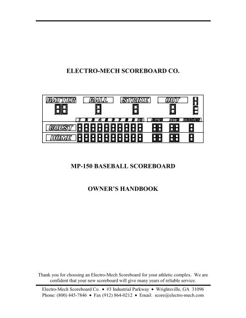
ELECTRO-MECH SCOREBOARD CO. MP-150 ... - Scoreboards
ELECTRO-MECH SCOREBOARD CO. MP-150 ... - Scoreboards
ELECTRO-MECH SCOREBOARD CO. MP-150 ... - Scoreboards

You also want an ePaper? Increase the reach of your titles
YUMPU automatically turns print PDFs into web optimized ePapers that Google loves.
Model <strong>MP</strong>-<strong>150</strong> Page 9ELECTRICAL <strong>CO</strong>NNECTIONSWe recommend a qualified electrician perform the needed electrical connections toensure proper operation of your scoreboard. These connections include grounding thescoreboard, connecting the scoreboard to a power source, making power and controlconnections between the two sections, installing the control cable, and connecting thecontrol console. Note: This manual makes references to numbered positions ofterminal strips inside the scoreboard. The terminal strip positions are not markedinside the scoreboard. All of the terminal strips in this scoreboard are sequentiallynumbered starting with position 1 on the left end.Ground ConnectionThe National Electrical Code requires a scoreboard (electric sign) to be grounded.Grounding the scoreboard helps the scoreboard electronics operate properly and helpsminimize damage if it is struck by lightning. Metal posts do not provide an adequateground path when they are placed in concrete. One method of grounding is to connecteach section of the scoreboard to one or more grounding rods which are driven into theground near the scoreboard via a large gauge copper wire. The self tapping sheet metalscrews on the back of the scoreboard cabinet provide a convenient connection point.Top Access Panel Power ConnectionRemove the knockout panel below the top access panel (figure 5).Figure 5 Rear Access PanelsThe power cable that is attached to a terminal block (T2) that is labeled “power frommiddle section”. The control cable that is attached to a terminal block (T1) that is labeled“control from bottom section”. Punch out two knockouts and run the cables through theknockouts. Reattach the knockout panel. Punch out the knockouts below the middleaccess panel. Connect the power cable to T4 (labeled “power to top section”) on thejunction chassis behind the middle access panel according to the table on the next page.Figure 6 shows the view behind the middle access panel. It is a good idea to run thiscable in conduit.Electro-Mech Scoreboard Co. • #3 Industrial Parkway • Wrightsville, GA 31096Phone: (800) 445-7846 • Fax (912) 864-0212 • Email: score@electro-mech.com
Model <strong>MP</strong>-<strong>150</strong> Page 10WIRE TOAC-L (black) T4-1AC-N (white) T4-2MTL3-01 MTL2-01 MTL1-01T11/2 A 5A 5A 5A 5A 5A 5A 5A 5A 5A 5A 5A 5A 5A 5A 5AF16 F15 F14 F13 F12 F11 F10 F9 F8 F7 F6 F5 F4 F3 F2 F1S13T2T3 T4 T5 T6Figure 6 Middle Access Panel RemovedBottom Access Panel Power ConnectionRemove the knockout panel below the bottom access panel. The power cable that isattached to a terminal block (T3) that is labeled “power from middle section. The controlcable that is attached to a terminal block (T1) that is labeled “control from middlesection”. Punch out two knockouts and run the cables through the knockouts. Reattachthe knockout panel. Punch out the knockouts below the middle access panel. Connectthe power cable to T6 on the junction chassis behind the middle access panel according tothe table below. It is a good idea to run this cable in conduit.WIRE TOAC-L (black) T6-1AC-N (white) T6-2Top Access Panel Control Cable ConnectionConnect the top access panel control cable to T2 on the junction chassis behind thebottom access panel (labeled “control to top section”) according to the table below.Figure 7 shows the view behind the bottom access panel. It is a good idea to run thiscable in conduit.WIRETOblack bottom access panel T2-1red bottom access panel T2-2shield bottom access panel T2-3Electro-Mech Scoreboard Co. • #3 Industrial Parkway • Wrightsville, GA 31096Phone: (800) 445-7846 • Fax (912) 864-0212 • Email: score@electro-mech.com
Model <strong>MP</strong>-<strong>150</strong> Page 11MBL3-01 MBL2-01 MBL1-01T11/2 A 5A 5A 5A 5A 5A 5A 5A 5A 5A 5A 5A 5A 5A 5A 5AF16 F15 F14 F13 F12 F11 F10 F9 F8 F7 F6 F5 F4 F3 F2 F1S13T2T3Figure 7 Bottom Access Panel RemovedBottom Access Panel Control Cable ConnectionConnect the bottom access panel control cable to T2 on the junction chassis behind themiddle access panel (labeled “control to bottom section”) according to the table below. Itis a good idea to run this cable in conduit.WIRETOblack middle access panel T2-1red middle access panel T2-2shield middle access panel T2-3Connecting The Scoreboard To Your Power SourceThe scoreboard may be connected to 240 VAC single phase or 120 VAC service at thescoreboard. Maximum power consumption of Model <strong>MP</strong>-<strong>150</strong>: 10980 Watts. Makesure that the power cables are rated for this electrical load. Electro-Mech ScoreboardCompany recommends that your power cable is installed in conduit. Avoid running yourpower cables in close proximity to your control cable. The following steps describe howto connect the scoreboard to your power source:1. Remove the hex head screws which hold the middle access panel on the rear of thescoreboard in place.2. Punch out the knockouts for the power and control cables.3. Feed the power cables through a knockout.4. If you are going to connect the scoreboard to a 240 VAC supply, connect one AC linewire to position 2, AC neutral wire to position 3, and the other AC line wire toposition 4 of terminal strip T5 on the junction chassis according to figure 8.Electro-Mech Scoreboard Co. • #3 Industrial Parkway • Wrightsville, GA 31096Phone: (800) 445-7846 • Fax (912) 864-0212 • Email: score@electro-mech.com
Model <strong>MP</strong>-<strong>150</strong> Page 13Electro-Mech Scoreboard Company suggests that you install a power cut-off switch and aNEMA 5-15R receptacle in a weatherproof box on the scoreboard post below thescoreboard. The cut-off switch provides a convenient way of turning the scoreboard offduring maintenance or repairs. The NEMA 5-15R receptacle will allow a technician toeasily plug in the control console and operate the scoreboard via the test jack S13 behindthe middle access panel (a valuable trouble-shooting aid).ScoreLink 300The S<strong>CO</strong>RELINK 300 RF MODEM SET is intended to eliminate the control cablebetween the scoreboard and the control console on Electro-Mech Scoreboard MM and<strong>MP</strong> series scoreboards. If you have purchased this option, disregard the next section ofthis manual. Refer to the S<strong>CO</strong>RELINK 300 RF MODEM SET OWNER’SHANDBOOK for installation instructions.Installing The Control CableThe control cable connects the scoreboard to the control console. While the control cableis direct burial rated, Electro-Mech Scoreboard Company recommends that it is installedin conduit to protect it from being cut. A small junction box with a stereo jack mountedon the face plate is attached to the control cable at the point of operation of thescoreboard. This junction box should be securely mounted in a clean, dry area within tenfeet of the rear of the control console. Most customers order the control cable with thejunction box attached. Some customers prefer to attach the junction box after the cable isinstalled. Those customers must match their stereo jack to one of the stereo jacks infigure 10 in order to make the proper connections. These connections should be soldered.STEREN1/4" STEREO JACKSWITCHCRAFT1/4" STEREO JACKORANGETAN13 2PIN 1 - BLACK WIREPIN 2 - RED WIREPIN 3 - SHIELD, GREEN WIRE2 31Figure 10 STEREO JACK WIRING DIAGRAMElectro-Mech Scoreboard Co. • #3 Industrial Parkway • Wrightsville, GA 31096Phone: (800) 445-7846 • Fax (912) 864-0212 • Email: score@electro-mech.com
Model <strong>MP</strong>-<strong>150</strong> Page 14The following steps describe how to connect the control cable to the scoreboard:1. At the rear of the scoreboard feed the control cable through one of the knockoutsbelow the middle access panel.2. Crimp fork terminals to the control cable wires and the shield.3. Connect the control cable to terminal strip T1 (located to the left of the test jack S13)according to the diagram in figure 11.BLACK RED SHIELDFigure 11 T1 WIRING DIAGRAMConnecting The Control ConsoleThe control console is normally connected to the junction box via the 10 ft. extensioncable. This extra length of cable allows the scoreboard operator some mobility and theability to store the control console after the game. The extension cable has two moldedstereo plugs attached to it. One end of the extension cable is plugged into the junctionbox stereo jack and the other end is plugged into the stereo jack mounted on the controlconsole back plate. The control console power cord is plugged into a grounded NEMA 5-15R 120 VAC receptacle.Electro-Mech Scoreboard Co. • #3 Industrial Parkway • Wrightsville, GA 31096Phone: (800) 445-7846 • Fax (912) 864-0212 • Email: score@electro-mech.com
Model <strong>MP</strong>-<strong>150</strong> Page 15<strong>S<strong>CO</strong>REBOARD</strong> OPERATIONThe <strong>MP</strong>-<strong>150</strong> Scoreboard is operated by the control console. No scoreboard functionswill operate without connecting the control console. Figure 12 shows the keypadlayout on your control console. The keypad functions are described in the text below thefigure.<strong>ELECTRO</strong>-<strong>MECH</strong> <strong>S<strong>CO</strong>REBOARD</strong> <strong>CO</strong>.P.O. BOX 102 #3 INDUSTRIAL PARKWAYWRIGHTSVILLE, GA 31096(912) 864-3366SETSET.1 SECAUTOHORN.1 SE<strong>CO</strong>N /OFFTIMEOFDAYUP /DOWNTIMEOUTTIMERBASEBALL / SOFTBALL7 8 9DIMMERSETBATTERINCINNINGT / BSETTOTALRUNSSETTOTALHITSSETTOTALERRORSRUNS HITS ERRS+1 +1 +14 5 61 2 3CLEARFLASHHITS0ENTERFLASHERRORSNEWGAMESETRUNS /INNINGSETINNINGT/ BHORNON /OFFFigure 12 Keypad LayoutControl Console Key Functions1. SET BATTER – Press [SET BATTER][2][5][ENTER] to display Batter number 25.Electro-Mech Scoreboard Co. • #3 Industrial Parkway • Wrightsville, GA 31096Phone: (800) 445-7846 • Fax (912) 864-0212 • Email: score@electro-mech.com
Model <strong>MP</strong>-<strong>150</strong> Page 162. SET TOTAL RUNS – Press [SET TOTAL RUNS]. The LCD display will read:00 D15:00 00TOT RUNS TOPPress [3][ENTER] to set the Visitor runs to 3. The LCD display will then read:03 D15:00 00TOT RUNS BOTPress [2][ENTER] to set the Home runs to 2.3. SET TOTAL HITS – Press [SET TOTAL HITS]. The LCD display will read:03 D15:00 02TOT HITS TOPPress [5][ENTER] to set the Visitor hits to 5. The LCD display will then read:03 D15:00 02TOT HITS BOTPress [1][ENTER] to set the Home hits to 1.4. SET TOTAL ERRORS – Press [SET TOTAL ERRORS]. The LCD display willread:03 D15:00 02TOT ERRS TOPPress [4][ENTER] to set the Visitor errors to 4. The LCD display will then read:03 D15:00 02TOT ERRS BOTPress [2][ENTER] to set the Home errors to 2.5. INC INNING T / B – This key increments the inning to the next half inning. Whenthe console is turned on, the LCD display will read:03 D15:00 02INNING -Press [INC INNING T / B]. The LCD display will then read:03 D15:00 03INNING 01 TOPThe console is set to the top of the first inning. Pressing the key again increments the consoleto the bottom of the first inning.Electro-Mech Scoreboard Co. • #3 Industrial Parkway • Wrightsville, GA 31096Phone: (800) 445-7846 • Fax (912) 864-0212 • Email: score@electro-mech.com
Model <strong>MP</strong>-<strong>150</strong> Page 176. RUNS +1 – This key will increment the total runs by 1.7. HITS +1 – This key will increment the total hits by 1.8. ERRORS +1 – This key will increment the total errors by 1. The error will getcounted against the team NOT at bat. For example, if the Visitor team is batting inthe top of the first inning and an error is committed, then it would be charged againstthe Home team. Pressing [ERRORS +1] will increment the Home errors.9. BALLS +1 – This key will increment the Balls by 1.10. STRIKES +1 – This key will increment the Strikes by 1.11. OUTS +1 – This key will increment the Outs by 1.12. DIMMER – This key will dim all the scoreboard lamps.13. NEW GAME – This key can be used to reset all scoreboard functions. Press [NEWGAME] and the LCD display will read:RESET YES<strong>S<strong>CO</strong>REBOARD</strong> NOPress [1][ENTER] to reset the scoreboard.14. SET RUNS / INNING – This key is used to change the score in a previous inning.Press [SET RUNS / INNING] and the LCD display will read:03 D15:00 02RUNS-INNING Press [3], [ENTER] to set the runs in the third inning. The LCD display will read:03 D15:00 02RUNS-TOP Press [1], [ENTER] to change the score for the top of the third inning. The LCD displaywill read:03 D15:00 02RUNS-BOTTOM Press [0], [ENTER] to change the score for the bottom of the third inning. Note: Thetotal runs will not be updated automatically. You must use the SET TOTAL RUNS keyto update this information.Electro-Mech Scoreboard Co. • #3 Industrial Parkway • Wrightsville, GA 31096Phone: (800) 445-7846 • Fax (912) 864-0212 • Email: score@electro-mech.com
Model <strong>MP</strong>-<strong>150</strong> Page 1815. SET INNING T / B – This key is used to change the current inning.. Press [SETINNING T / B] and the LCD display will read:03 D15:00 02SET TO INN Press [5], [ENTER] to change to the fifth inning. The LCD display will read:03 D15:00 02TOP=0/BOT=1 Press [1], [ENTER] to select the bottom of the inning.16. CLEAR / FLASH HITS – This key has two purposes. It can be used to clearincorrect keypad entries. It can also be used to flash the hit symbol (H) on thescoreboard.17. ENTER / FLASH ERRORS – This key has two purposes. It is used when enteringgame information. It can also be used to flash the error symbol (E) on the scoreboard.The SET CLOCK, SET CLOCK .1 SEC, .1 SEC ON / OFF, CLOCK UP / DOWN,AUTO HORN, TIME OF DAY, TIME OUT TIMER, HORN ON / OFF, and CLOCKON/OFF keys are not used with the <strong>MP</strong>-<strong>150</strong> scoreboard.You should reset the scoreboard each time that it is turned on. Test out all the functionsto ensure that the scoreboard is operating properly. Electro-Mech ScoreboardCompany strongly advises that you unplug the control console, disconnect theextension cable at the control console, and turn the power to the scoreboard offwhen the scoreboard is not in use. The control console can not turn the scoreboardoff. This action will help protect the scoreboard and control console from power surgesand lightning strikes.Electro-Mech Scoreboard Co. • #3 Industrial Parkway • Wrightsville, GA 31096Phone: (800) 445-7846 • Fax (912) 864-0212 • Email: score@electro-mech.com
Model <strong>MP</strong>-<strong>150</strong> Page 19SERVICING THE <strong>S<strong>CO</strong>REBOARD</strong>While your scoreboard was designed for years of trouble-free operation, some problemsmay occasionally occur. Our trained personnel at Electro-Mech Scoreboard Company areready to answer your questions from Monday to Friday during the hours of 8 AM to 5 PMEastern Standard Time. Be sure to know your scoreboard model number when calling.Scoreboard replacement parts, including lamps, are always available. Electro-MechScoreboard Company can repair the control console and plug in modules at a significantsavings when compared to the price of new units. Our convenient toll free number islisted at the bottom of every page in this manual.Figure 13 shows the components behind the middle access panel.MTL3-01 MTL2-01 MTL1-01T11/2 A 5A 5A 5A 5A 5A 5A 5A 5A 5A 5A 5A 5A 5A 5A 5AF16 F15 F14 F13 F12 F11 F10 F9 F8 F7 F6 F5 F4 F3 F2 F1S13T2T3 T4 T5 T6Figure 13 Middle Access Panel ComponentsPlug in module MTL3-01 operates VISITOR RUNS, HITS, and ERRORS. Plug inmodule MTL2-01 operates the VISITOR runs for innings 6 through 10. Plug in moduleMTL1-01 operates the VISITOR runs for innings 1 through 5.Electro-Mech Scoreboard Co. • #3 Industrial Parkway • Wrightsville, GA 31096Phone: (800) 445-7846 • Fax (912) 864-0212 • Email: score@electro-mech.com
Model <strong>MP</strong>-<strong>150</strong> Page 20FUSESFUSE RATING FUNCTIONF1 5 A 250 V VISITOR INNING 1F2 5 A 250 V VISITOR INNING 2F3 5 A 250 V VISITOR INNING 3F4 5 A 250 V VISITOR INNING 4F5 5 A 250 V VISITOR INNING 5F6 5 A 250 V VISITOR INNING 6F7 5 A 250 V VISITOR INNING 7F8 5 A 250 V VISITOR INNING 8F9 5 A 250 V VISITOR INNING 9F10 5 A 250 V VISITOR INNING 10F11 5 A 250 V VISITOR RUNS UNITSF12 5 A 250 V VISITOR RUNS TENSF13 5 A 250 V VISITOR HITS UNITSF14 5 A 250 V VISITOR HITS TENSF15 5 A 250 V VISITOR ERRORF16 1/2 A 250 V <strong>CO</strong>NTROL LINE<strong>CO</strong>NNECTION POINTSTERMINAL STRIPFUNCTIONT-1 control cable connectionT-2 control cable to bottom access panelT-3 MOV (surge protection)T-4 power cable connectionT-5 power to top access panelT-6 power to bottom access panelS-13 test jackFigure 14 shows the components behind the bottom access panel.Electro-Mech Scoreboard Co. • #3 Industrial Parkway • Wrightsville, GA 31096Phone: (800) 445-7846 • Fax (912) 864-0212 • Email: score@electro-mech.com
Model <strong>MP</strong>-<strong>150</strong> Page 21MBL3-01 MBL2-01 MBL1-01T11/2 A 5A 5A 5A 5A 5A 5A 5A 5A 5A 5A 5A 5A 5A 5A 5AF16 F15 F14 F13 F12 F11 F10 F9 F8 F7 F6 F5 F4 F3 F2 F1S13T2T3Figure 14 Bottom Access Panel ComponentsPlug in module MBL3-01 operates HOME RUNS, HITS, and ERRORS. Plug in moduleMBL2-01 operates the HOME runs for innings 6 through 10. Plug in module MBL1-01operates the HOME runs for innings 1 through 5.FUSESFUSE RATING FUNCTIONF1 5 A 250 V HOME INNING 1F2 5 A 250 V HOME INNING 2F3 5 A 250 V HOME INNING 3F4 5 A 250 V HOME INNING 4F5 5 A 250 V HOME INNING 5F6 5 A 250 V HOME INNING 6F7 5 A 250 V HOME INNING 7F8 5 A 250 V HOME INNING 8F9 5 A 250 V HOME INNING 9F10 5 A 250 V HOME INNING 10F11 5 A 250 V HOME RUNS UNITSF12 5 A 250 V HOME RUNS TENSF13 5 A 250 V HOME HITS UNITSF14 5 A 250 V HOME HITS TENSF15 5 A 250 V HOME ERRORF16 1/2 A 250 V <strong>CO</strong>NTROL LINEElectro-Mech Scoreboard Co. • #3 Industrial Parkway • Wrightsville, GA 31096Phone: (800) 445-7846 • Fax (912) 864-0212 • Email: score@electro-mech.com
Model <strong>MP</strong>-<strong>150</strong> Page 22<strong>CO</strong>NNECTION POINTSTERMINAL STRIPFUNCTIONT-1 control cable from middle access panelT-2 control cable to top access panelT-3 power from middle access panelS-13 test jackFigure 15 shows the components behind the top access panel. The plug in moduleMBAT-01 operates BALL, STRIKE, OUT BATTER NUMBER, HIT, and ERROR.MBAT-01T1S58AF68AF51/2 AF45AF35AF25AF1T2Figure 15 Top Access Panel ComponentsFUSESFUSE RATING FUNCTIONF1 5 A 250 V BALLF2 5 A 250 V STRIKEF3 5 A 250 V OUTF4 1/2 A 250 V <strong>CO</strong>NTROL LINEF5 8 A 250 V BATTER NUMBERF6 8 A 250 V HIT and ERRORElectro-Mech Scoreboard Co. • #3 Industrial Parkway • Wrightsville, GA 31096Phone: (800) 445-7846 • Fax (912) 864-0212 • Email: score@electro-mech.com
Model <strong>MP</strong>-<strong>150</strong> Page 23<strong>CO</strong>NNECTION POINTSTERMINAL STRIPFUNCTIONT-1 control cable from bottom access panelT-2 power cable from middle access panelS-5 test jackPLUG IN MODULE REPLACEMENTEach module has four bottom plugs which mate with sockets in the scoreboard. A screwlocated at the top of the module holds it against the scoreboard cabinet. Simply removethe screw and pull the module upward to unseat the module. To avoid damage to theplug in module, always turn off the power to the scoreboard when removing orreplacing it.LA<strong>MP</strong> REPLACEMENTReplacing lamps may be the only service you ever perform on your Electro-Mechscoreboard. The lamps are accessed by removing the protective mask covering each lampbank. To avoid damage to the plug in module, always turn off the power to thescoreboard when changing lamps. We recommend using a felt pen or tape to marklamps that will not light. This scoreboard uses 15 watt medium base lamps (also called15A15 lamps). Never replace these with higher wattage lamps.Electro-Mech Scoreboard Co. • #3 Industrial Parkway • Wrightsville, GA 31096Phone: (800) 445-7846 • Fax (912) 864-0212 • Email: score@electro-mech.com
Model <strong>MP</strong>-<strong>150</strong> Page 24<strong>ELECTRO</strong>-<strong>MECH</strong> <strong>S<strong>CO</strong>REBOARD</strong> <strong>CO</strong>.FIVE YEAR LIMITED WARRANTYTHE ELECTRICAL <strong>CO</strong><strong>MP</strong>ONENTS OF ALL <strong>ELECTRO</strong>-<strong>MECH</strong><strong>S<strong>CO</strong>REBOARD</strong>S ARE GUARANTEED FOR A PERIOD OF FIVE (5) YEARSFROM THE DATE OF INVOICE AGAINST DEFECTS IN WORKMANSHIPOR MATERIAL AND WILL BE REPLACED OR REPAIRED WITHOUT<strong>CO</strong>ST TO THE OWNER PROVIDED THE EQUIPMENT OR PARTS ARERETURNED POSTAGE-PAID TO THE FACTORY IN WRIGHTSVILLE, GA.SHIPPING BACK TO THE OWNER WILL BE VIA UPS GROUND SERVICEEXCEPT WHEN AIR OR SPECIAL METHOD OF RETURN IS SPECIFIED BYTHE OWNER, IN WHICH CASE SHIPPING WILL BE FREIGHT <strong>CO</strong>LLECT.EXCLUDED FROM THIS WARRANTY ARE LA<strong>MP</strong>S, FUSES ANDSOCKETS.THIS WARRANTY DOES NOT INCLUDE LABOR CHARGES INCURRED INTHE REMOVAL OF <strong>CO</strong><strong>MP</strong>ONENT PARTS, SERVICE CALLS, ORDAMAGES RESULTING FROM I<strong>MP</strong>ROPER INSTALLATION, I<strong>MP</strong>ROPEROPERATION, OR PROBLEMS CAUSED BY ANY REPAIR, ALTERATIONOR MODIFICATION OF THE <strong>S<strong>CO</strong>REBOARD</strong> NOT PERFORMED BY<strong>ELECTRO</strong>-<strong>MECH</strong>.EQUIPMENT WHICH IS SUBJECTED TO ACCIDENT, NEGLECT, ABUSE,MISUSE OR OTHER NATURAL DISASTERS, INCLUDING BUT NOTLIMITED TO FIRE, WIND, LIGHTNING, OR FLOOD, IS NOT <strong>CO</strong>VERED BYTHIS GUARANTEE.Electro-Mech Scoreboard Co. • #3 Industrial Parkway • Wrightsville, GA 31096Phone: (800) 445-7846 • Fax (912) 864-0212 • Email: score@electro-mech.com