IDEALARC R3R 375-I, 500-I AND 600-I - Lincoln Electric
IDEALARC R3R 375-I, 500-I AND 600-I - Lincoln Electric
IDEALARC R3R 375-I, 500-I AND 600-I - Lincoln Electric

Create successful ePaper yourself
Turn your PDF publications into a flip-book with our unique Google optimized e-Paper software.
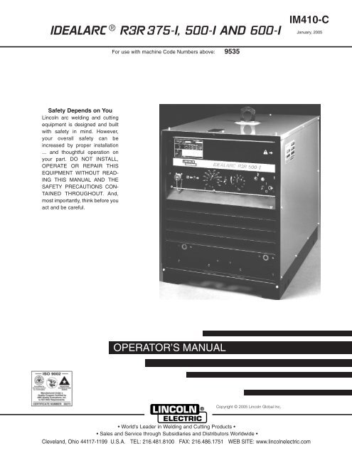
<strong>IDEALARC</strong> ® <strong>R3R</strong> <strong>375</strong>-I, <strong>500</strong>-I <strong>AND</strong> <strong>600</strong>-I<br />
IM410-C<br />
January, 2005<br />
For use with machine Code Numbers above: 9535<br />
Safety Depends on You<br />
<strong>Lincoln</strong> arc welding and cutting<br />
equipment is designed and built<br />
with safety in mind. However,<br />
your overall safety can be<br />
increased by proper installation<br />
... and thoughtful operation on<br />
your part. DO NOT INSTALL,<br />
OPERATE OR REPAIR THIS<br />
EQUIPMENT WITHOUT READ-<br />
ING THIS MANUAL <strong>AND</strong> THE<br />
SAFETY PRECAUTIONS CON-<br />
TAINED THROUGHOUT. And,<br />
most importantly, think before you<br />
act and be careful.<br />
OPERATOR’S MANUAL<br />
Copyright © 2005 <strong>Lincoln</strong> Global Inc.<br />
• World's Leader in Welding and Cutting Products •<br />
• Sales and Service through Subsidiaries and Distributors Worldwide •<br />
Cleveland, Ohio 44117-1199 U.S.A. TEL: 216.481.8100 FAX: 216.486.1751 WEB SITE: www.lincolnelectric.com
i<br />
Diesel engine exhaust and some of its constituents<br />
are known to the State of California to cause cancer,<br />
birth defects, and other reproductive harm.<br />
The Above For Diesel Engines<br />
FOR ENGINE<br />
powered equipment.<br />
1.a. Turn the engine off before troubleshooting and maintenance<br />
work unless the maintenance work requires it to be running.<br />
____________________________________________________<br />
1.b.Operate engines in open, well-ventilated<br />
areas or vent the engine exhaust fumes<br />
outdoors.<br />
____________________________________________________<br />
1.c. Do not add the fuel near an open flame welding<br />
arc or when the engine is running. Stop<br />
the engine and allow it to cool before refueling<br />
to prevent spilled fuel from vaporizing on<br />
contact with hot engine parts and igniting. Do<br />
not spill fuel when filling tank. If fuel is spilled,<br />
wipe it up and do not start engine until fumes<br />
have been eliminated.<br />
____________________________________________________<br />
1.d. Keep all equipment safety guards, covers<br />
and devices in position and in good<br />
repair.Keep hands, hair, clothing and tools<br />
away from V-belts, gears, fans and all other<br />
moving parts when starting, operating or<br />
repairing equipment.<br />
____________________________________________________<br />
1.e. In some cases it may be necessary to remove safety<br />
guards to perform required maintenance. Remove<br />
guards only when necessary and replace them when the<br />
maintenance requiring their removal is complete.<br />
Always use the greatest care when working near moving<br />
parts.<br />
___________________________________________________<br />
1.f. Do not put your hands near the engine fan. Do not attempt to<br />
override the governor or idler by pushing on the throttle control<br />
rods while the engine is running.<br />
___________________________________________________<br />
1.g. To prevent accidentally starting gasoline engines while<br />
turning the engine or welding generator during maintenance<br />
work, disconnect the spark plug wires, distributor cap or<br />
magneto wire as appropriate.<br />
SAFETY<br />
WARNING<br />
CALIFORNIA PROPOSITION 65 WARNINGS<br />
The engine exhaust from this product contains<br />
chemicals known to the State of California to cause<br />
cancer, birth defects, or other reproductive harm.<br />
The Above For Gasoline Engines<br />
ARC WELDING CAN BE HAZARDOUS. PROTECT YOURSELF <strong>AND</strong> OTHERS FROM POSSIBLE SERIOUS INJURY OR DEATH.<br />
KEEP CHILDREN AWAY. PACEMAKER WEARERS SHOULD CONSULT WITH THEIR DOCTOR BEFORE OPERATING.<br />
Read and understand the following safety highlights. For additional safety information, it is strongly recommended that you<br />
purchase a copy of “Safety in Welding & Cutting - ANSI Standard Z49.1” from the American Welding Society, P.O. Box 351040,<br />
Miami, Florida 33135 or CSA Standard W117.2-1974. A Free copy of “Arc Welding Safety” booklet E205 is available from the<br />
<strong>Lincoln</strong> <strong>Electric</strong> Company, 22801 St. Clair Avenue, Cleveland, Ohio 44117-1199.<br />
BE SURE THAT ALL INSTALLATION, OPERATION, MAINTENANCE <strong>AND</strong> REPAIR PROCEDURES ARE<br />
PERFORMED ONLY BY QUALIFIED INDIVIDUALS.<br />
Mar ‘95<br />
1.h. To avoid scalding, do not remove the<br />
radiator pressure cap when the engine is<br />
hot.<br />
ELECTRIC <strong>AND</strong><br />
MAGNETIC FIELDS<br />
may be dangerous<br />
2.a. <strong>Electric</strong> current flowing through any conductor causes<br />
localized <strong>Electric</strong> and Magnetic Fields (EMF). Welding<br />
current creates EMF fields around welding cables and<br />
welding machines<br />
2.b. EMF fields may interfere with some pacemakers, and<br />
welders having a pacemaker should consult their physician<br />
before welding.<br />
2.c. Exposure to EMF fields in welding may have other health<br />
effects which are now not known.<br />
2.d. All welders should use the following procedures in order to<br />
minimize exposure to EMF fields from the welding circuit:<br />
2.d.1. Route the electrode and work cables together - Secure<br />
them with tape when possible.<br />
2.d.2. Never coil the electrode lead around your body.<br />
2.d.3. Do not place your body between the electrode and<br />
work cables. If the electrode cable is on your right<br />
side, the work cable should also be on your right side.<br />
2.d.4. Connect the work cable to the workpiece as close as<br />
possible to the area being welded.<br />
2.d.5. Do not work next to welding power source.<br />
i
ii<br />
ELECTRIC SHOCK can kill.<br />
3.a. The electrode and work (or ground) circuits<br />
are electrically “hot” when the welder is on.<br />
Do not touch these “hot” parts with your bare<br />
skin or wet clothing. Wear dry, hole-free<br />
gloves to insulate hands.<br />
SAFETY<br />
ARC RAYS can burn.<br />
4.a. Use a shield with the proper filter and cover<br />
plates to protect your eyes from sparks and<br />
the rays of the arc when welding or observing<br />
open arc welding. Headshield and filter lens<br />
should conform to ANSI Z87. I standards.<br />
ii<br />
3.b. Insulate yourself from work and ground using dry insulation.<br />
Make certain the insulation is large enough to cover your full<br />
area of physical contact with work and ground.<br />
In addition to the normal safety precautions, if welding<br />
must be performed under electrically hazardous<br />
conditions (in damp locations or while wearing wet<br />
clothing; on metal structures such as floors, gratings or<br />
scaffolds; when in cramped positions such as sitting,<br />
kneeling or lying, if there is a high risk of unavoidable or<br />
accidental contact with the workpiece or ground) use<br />
the following equipment:<br />
• Semiautomatic DC Constant Voltage (Wire) Welder.<br />
• DC Manual (Stick) Welder.<br />
• AC Welder with Reduced Voltage Control.<br />
3.c. In semiautomatic or automatic wire welding, the electrode,<br />
electrode reel, welding head, nozzle or semiautomatic<br />
welding gun are also electrically “hot”.<br />
3.d. Always be sure the work cable makes a good electrical<br />
connection with the metal being welded. The connection<br />
should be as close as possible to the area being welded.<br />
3.e. Ground the work or metal to be welded to a good electrical<br />
(earth) ground.<br />
3.f.<br />
Maintain the electrode holder, work clamp, welding cable and<br />
welding machine in good, safe operating condition. Replace<br />
damaged insulation.<br />
3.g. Never dip the electrode in water for cooling.<br />
3.h. Never simultaneously touch electrically “hot” parts of<br />
electrode holders connected to two welders because voltage<br />
between the two can be the total of the open circuit voltage<br />
of both welders.<br />
3.i.<br />
When working above floor level, use a safety belt to protect<br />
yourself from a fall should you get a shock.<br />
3.j. Also see Items 6.c. and 8.<br />
4.b. Use suitable clothing made from durable flame-resistant<br />
material to protect your skin and that of your helpers from<br />
the arc rays.<br />
4.c. Protect other nearby personnel with suitable, non-flammable<br />
screening and/or warn them not to watch the arc nor expose<br />
themselves to the arc rays or to hot spatter or metal.<br />
FUMES <strong>AND</strong> GASES<br />
can be dangerous.<br />
5.a. Welding may produce fumes and gases<br />
hazardous to health. Avoid breathing these<br />
fumes and gases.When welding, keep<br />
your head out of the fume. Use enough<br />
ventilation and/or exhaust at the arc to keep<br />
fumes and gases away from the breathing zone. When<br />
welding with electrodes which require special<br />
ventilation such as stainless or hard facing (see<br />
instructions on container or MSDS) or on lead or<br />
cadmium plated steel and other metals or coatings<br />
which produce highly toxic fumes, keep exposure as<br />
low as possible and below Threshold Limit Values (TLV)<br />
using local exhaust or mechanical ventilation. In<br />
confined spaces or in some circumstances, outdoors, a<br />
respirator may be required. Additional precautions are<br />
also required when welding on galvanized steel.<br />
5.b. Do not weld in locations near chlorinated hydrocarbon vapors<br />
coming from degreasing, cleaning or spraying operations.<br />
The heat and rays of the arc can react with solvent vapors to<br />
form phosgene, a highly toxic gas, and other irritating<br />
products.<br />
5.c. Shielding gases used for arc welding can displace air and<br />
cause injury or death. Always use enough ventilation,<br />
especially in confined areas, to insure breathing air is safe.<br />
5.d. Read and understand the manufacturer’s instructions for this<br />
equipment and the consumables to be used, including the<br />
material safety data sheet (MSDS) and follow your<br />
employer’s safety practices. MSDS forms are available from<br />
your welding distributor or from the manufacturer.<br />
5.e. Also see item 1.b.<br />
Mar ‘95
iii<br />
SAFETY<br />
iii<br />
WELDING SPARKS can<br />
cause fire or explosion.<br />
6.a. Remove fire hazards from the welding area.<br />
If this is not possible, cover them to prevent<br />
the welding sparks from starting a fire.<br />
Remember that welding sparks and hot<br />
materials from welding can easily go through small cracks<br />
and openings to adjacent areas. Avoid welding near<br />
hydraulic lines. Have a fire extinguisher readily available.<br />
6.b. Where compressed gases are to be used at the job site,<br />
special precautions should be used to prevent hazardous<br />
situations. Refer to “Safety in Welding and Cutting” (ANSI<br />
Standard Z49.1) and the operating information for the<br />
equipment being used.<br />
6.c. When not welding, make certain no part of the electrode<br />
circuit is touching the work or ground. Accidental contact can<br />
cause overheating and create a fire hazard.<br />
6.d. Do not heat, cut or weld tanks, drums or containers until the<br />
proper steps have been taken to insure that such procedures<br />
will not cause flammable or toxic vapors from substances<br />
inside. They can cause an explosion even though they have<br />
been “cleaned”. For information, purchase “Recommended<br />
Safe Practices for the Preparation for Welding and Cutting of<br />
Containers and Piping That Have Held Hazardous<br />
Substances”, AWS F4.1 from the American Welding Society<br />
(see address above).<br />
6.e. Vent hollow castings or containers before heating, cutting or<br />
welding. They may explode.<br />
6.f. Sparks and spatter are thrown from the welding arc. Wear oil<br />
free protective garments such as leather gloves, heavy shirt,<br />
cuffless trousers, high shoes and a cap over your hair. Wear<br />
ear plugs when welding out of position or in confined places.<br />
Always wear safety glasses with side shields when in a<br />
welding area.<br />
6.g. Connect the work cable to the work as close to the welding<br />
area as practical. Work cables connected to the building<br />
framework or other locations away from the welding area<br />
increase the possibility of the welding current passing<br />
through lifting chains, crane cables or other alternate circuits.<br />
This can create fire hazards or overheat lifting chains or<br />
cables until they fail.<br />
6.h. Also see item 1.c.<br />
CYLINDER may explode<br />
if damaged.<br />
7.a. Use only compressed gas cylinders<br />
containing the correct shielding gas for the<br />
process used and properly operating<br />
regulators designed for the gas and<br />
pressure used. All hoses, fittings, etc. should be suitable for<br />
the application and maintained in good condition.<br />
7.b. Always keep cylinders in an upright position securely<br />
chained to an undercarriage or fixed support.<br />
7.c. Cylinders should be located:<br />
• Away from areas where they may be struck or subjected to<br />
physical damage.<br />
• A safe distance from arc welding or cutting operations and<br />
any other source of heat, sparks, or flame.<br />
7.d. Never allow the electrode, electrode holder or any other<br />
electrically “hot” parts to touch a cylinder.<br />
7.e. Keep your head and face away from the cylinder valve outlet<br />
when opening the cylinder valve.<br />
7.f.<br />
Valve protection caps should always be in place and hand<br />
tight except when the cylinder is in use or connected for<br />
use.<br />
7.g. Read and follow the instructions on compressed gas<br />
cylinders, associated equipment, and CGA publication P-l,<br />
“Precautions for Safe Handling of Compressed Gases in<br />
Cylinders,” available from the Compressed Gas Association<br />
1235 Jefferson Davis Highway, Arlington, VA 22202.<br />
FOR ELECTRICALLY<br />
powered equipment.<br />
8.a. Turn off input power using the disconnect<br />
switch at the fuse box before working on<br />
the equipment.<br />
8.b. Install equipment in accordance with the U.S. National<br />
<strong>Electric</strong>al Code, all local codes and the manufacturer’s<br />
recommendations.<br />
8.c. Ground the equipment in accordance with the U.S. National<br />
<strong>Electric</strong>al Code and the manufacturer’s recommendations.<br />
Mar ‘95<br />
<strong>IDEALARC</strong> <strong>R3R</strong> <strong>375</strong>-I, <strong>500</strong>-I <strong>AND</strong> <strong>600</strong>-I
iv<br />
SAFETY<br />
iv<br />
PRÉCAUTIONS DE SÛRETÉ<br />
Pour votre propre protection lire et observer toutes les instructions<br />
et les précautions de sûreté specifiques qui parraissent dans ce<br />
manuel aussi bien que les précautions de sûreté générales suivantes:<br />
Sûreté Pour Soudage A L’Arc<br />
1. Protegez-vous contre la secousse électrique:<br />
a. Les circuits à l’électrode et à la piéce sont sous tension<br />
quand la machine à souder est en marche. Eviter toujours<br />
tout contact entre les parties sous tension et la peau nue<br />
ou les vétements mouillés. Porter des gants secs et sans<br />
trous pour isoler les mains.<br />
b. Faire trés attention de bien s’isoler de la masse quand on<br />
soude dans des endroits humides, ou sur un plancher metallique<br />
ou des grilles metalliques, principalement dans<br />
les positions assis ou couché pour lesquelles une grande<br />
partie du corps peut être en contact avec la masse.<br />
c. Maintenir le porte-électrode, la pince de masse, le câble de<br />
soudage et la machine à souder en bon et sûr état defonctionnement.<br />
d.Ne jamais plonger le porte-électrode dans l’eau pour le<br />
refroidir.<br />
e. Ne jamais toucher simultanément les parties sous tension<br />
des porte-électrodes connectés à deux machines à souder<br />
parce que la tension entre les deux pinces peut être le total<br />
de la tension à vide des deux machines.<br />
f. Si on utilise la machine à souder comme une source de<br />
courant pour soudage semi-automatique, ces precautions<br />
pour le porte-électrode s’applicuent aussi au pistolet de<br />
soudage.<br />
2. Dans le cas de travail au dessus du niveau du sol, se protéger<br />
contre les chutes dans le cas ou on recoit un choc. Ne jamais<br />
enrouler le câble-électrode autour de n’importe quelle partie du<br />
corps.<br />
3. Un coup d’arc peut être plus sévère qu’un coup de soliel, donc:<br />
6. Eloigner les matériaux inflammables ou les recouvrir afin de<br />
prévenir tout risque d’incendie dû aux étincelles.<br />
7. Quand on ne soude pas, poser la pince à une endroit isolé de<br />
la masse. Un court-circuit accidental peut provoquer un<br />
échauffement et un risque d’incendie.<br />
8. S’assurer que la masse est connectée le plus prés possible de<br />
la zone de travail qu’il est pratique de le faire. Si on place la<br />
masse sur la charpente de la construction ou d’autres endroits<br />
éloignés de la zone de travail, on augmente le risque de voir<br />
passer le courant de soudage par les chaines de levage,<br />
câbles de grue, ou autres circuits. Cela peut provoquer des<br />
risques d’incendie ou d’echauffement des chaines et des<br />
câbles jusqu’à ce qu’ils se rompent.<br />
9. Assurer une ventilation suffisante dans la zone de soudage.<br />
Ceci est particuliérement important pour le soudage de tôles<br />
galvanisées plombées, ou cadmiées ou tout autre métal qui<br />
produit des fumeés toxiques.<br />
10. Ne pas souder en présence de vapeurs de chlore provenant<br />
d’opérations de dégraissage, nettoyage ou pistolage. La<br />
chaleur ou les rayons de l’arc peuvent réagir avec les vapeurs<br />
du solvant pour produire du phosgéne (gas fortement toxique)<br />
ou autres produits irritants.<br />
11. Pour obtenir de plus amples renseignements sur la sûreté, voir<br />
le code “Code for safety in welding and cutting” CSA Standard<br />
W 117.2-1974.<br />
PRÉCAUTIONS DE SÛRETÉ POUR<br />
LES MACHINES À SOUDER À<br />
TRANSFORMATEUR ET À<br />
REDRESSEUR<br />
a. Utiliser un bon masque avec un verre filtrant approprié ainsi<br />
qu’un verre blanc afin de se protéger les yeux du rayonnement<br />
de l’arc et des projections quand on soude ou<br />
quand on regarde l’arc.<br />
b. Porter des vêtements convenables afin de protéger la peau<br />
de soudeur et des aides contre le rayonnement de l‘arc.<br />
c. Protéger l’autre personnel travaillant à proximité au<br />
soudage à l’aide d’écrans appropriés et non-inflammables.<br />
4. Des gouttes de laitier en fusion sont émises de l’arc de<br />
soudage. Se protéger avec des vêtements de protection libres<br />
de l’huile, tels que les gants en cuir, chemise épaisse, pantalons<br />
sans revers, et chaussures montantes.<br />
1. Relier à la terre le chassis du poste conformement au code de<br />
l’électricité et aux recommendations du fabricant. Le dispositif<br />
de montage ou la piece à souder doit être branché à une<br />
bonne mise à la terre.<br />
2. Autant que possible, I’installation et l’entretien du poste seront<br />
effectués par un électricien qualifié.<br />
3. Avant de faires des travaux à l’interieur de poste, la debrancher<br />
à l’interrupteur à la boite de fusibles.<br />
4. Garder tous les couvercles et dispositifs de sûreté à leur place.<br />
5. Toujours porter des lunettes de sécurité dans la zone de<br />
soudage. Utiliser des lunettes avec écrans lateraux dans les<br />
zones où l’on pique le laitier.<br />
Mar. ‘93
v<br />
Thank You<br />
for selecting a QUALITY product by <strong>Lincoln</strong> <strong>Electric</strong>. We want you<br />
to take pride in operating this <strong>Lincoln</strong> <strong>Electric</strong> Company product •••<br />
as much pride as we have in bringing this product to you!<br />
v<br />
Please Examine Carton and Equipment For Damage Immediately<br />
When this equipment is shipped, title passes to the purchaser upon receipt by the carrier. Consequently, Claims<br />
for material damaged in shipment must be made by the purchaser against the transportation company at the time<br />
the shipment is received.<br />
Please record your equipment identification information below for future reference. This information can be found<br />
on your machine nameplate.<br />
Product _________________________________________________________________________________<br />
Model Number ___________________________________________________________________________<br />
Code Number or Date Code_________________________________________________________________<br />
Serial Number____________________________________________________________________________<br />
Date Purchased___________________________________________________________________________<br />
Where Purchased_________________________________________________________________________<br />
Whenever you request replacement parts or information on this equipment, always supply the information you<br />
have recorded above. The code number is especially important when identifying the correct replacement parts.<br />
Read this Operators Manual completely before attempting to use this equipment. Save this manual and keep it<br />
handy for quick reference. Pay particular attention to the safety instructions we have provided for your protection.<br />
The level of seriousness to be applied to each is explained below:<br />
WARNING<br />
On-Line Product Registration<br />
- Register your machine with <strong>Lincoln</strong> <strong>Electric</strong> either via fax or over the Internet.<br />
• For faxing: Complete the form on the back of the warranty statement included in the literature packet<br />
accompanying this machine and fax the form per the instructions printed on it.<br />
• For On-Line Registration: Go to our WEB SITE at www.lincolnelectric.com. Choose “Quick Links” and then<br />
“Product Registration”. Please complete the form and submit your registration.<br />
This statement appears where the information must be followed exactly to avoid serious personal injury or<br />
loss of life.<br />
CAUTION<br />
This statement appears where the information must be followed to avoid minor personal injury or damage to<br />
this equipment.
vi<br />
TABLE OF CONTENTS<br />
vi<br />
Page<br />
Installation . . . . . . . . . . . . . . . . . . . . . . . . . . . . . . . . . . . . . . . . . . . . . . . . . . . . . . . Section A<br />
Input Power Connection . . . . . . . . . . . . . . . . . . . . . . . . . . . . . . . . . . . . . . . . . . . . . . . A-1<br />
Duty Cycle . . . . . . . . . . . . . . . . . . . . . . . . . . . . . . . . . . . . . . . . . . . . . . . . . . . . . . . . . A-1<br />
Output Connections . . . . . . . . . . . . . . . . . . . . . . . . . . . . . . . . . . . . . . . . . . . . . . . . . . A-1<br />
Operating Instructions . . . . . . . . . . . . . . . . . . . . . . . . . . . . . . . . . . . . . . . . . . . . . Section B<br />
Accessories . . . . . . . . . . . . . . . . . . . . . . . . . . . . . . . . . . . . . . . . . . . . . . . . . . . . . Section C<br />
Maintenance . . . . . . . . . . . . . . . . . . . . . . . . . . . . . . . . . . . . . . . . . . . . . . . . . . . . . Section D<br />
Troubleshooting . . . . . . . . . . . . . . . . . . . . . . . . . . . . . . . . . . . . . . . . . . . . . . . . . . Section E<br />
Troubleshooting Procedures . . . . . . . . . . . . . . . . . . . . . . . . . . . . . . . . . . . . . . E-7 – E-10<br />
Wiring Diagrams . . . . . . . . . . . . . . . . . . . . . . . . . . . . . . . . . . . . . . . . . . . . . . . . . . Section F<br />
Parts Lists<br />
. . . . . . . . . . . . . . . . . . . . . . . . . . . . . . . . . . . . . . . . . . . . . . . . . . . . P206 Series<br />
<strong>IDEALARC</strong> <strong>R3R</strong> <strong>375</strong>-I, <strong>500</strong>-I <strong>AND</strong> <strong>600</strong>-I
A-1<br />
INSTALLATION<br />
WARNING<br />
FALLING EQUIPMENT can cause<br />
injury.<br />
• Do not lift this machine using lift<br />
bail if it is equipped with a heavy<br />
• accessory such as trailer or gas cylinder.<br />
• Lift only with equipment of adequate lifting<br />
capacity.<br />
• Be sure machine is stable when lifting.<br />
The machine should be located in a clean, dry place<br />
where there is free circulation of clean air, such that air<br />
movement entering the front and exiting the back will<br />
not be restricted. Dirt and dust that can be drawn into<br />
the machine should be kept to a minimum. Failure to<br />
observe these precautions can result in excessive<br />
operating temperatures and nuisance shutdown of the<br />
machine.<br />
The Idealarc <strong>R3R</strong> welders can be stacked three high<br />
when the following precautions are observed:<br />
1. Be sure the bottom machine is on a firm, level surface<br />
suitable for the total weight [up to 1340 pounds<br />
(608 kg)] of the stacked machines.<br />
2. Stack the machines with the fronts flush. Be certain<br />
the pins on the top front corners of the lower<br />
machines fit through the holes in the base rails of<br />
the upper machines.<br />
3. No unit heavier than the bottom unit should be<br />
stacked on top of it. For example, an <strong>R3R</strong> <strong>500</strong>-I<br />
shall not be slacked on top of an <strong>R3R</strong> 400-I, but an<br />
<strong>R3R</strong> 400-I may be stacked on top of an <strong>R3R</strong> <strong>500</strong>-I.<br />
INPUT POWER CONNECTION<br />
WARNING<br />
ELECTRIC SHOCK can kill.<br />
• Have an electrician install and service<br />
this equipment.<br />
• Turn the input power off at the fuse<br />
box before working on equipment.<br />
• Do not touch electrically hot parts.<br />
INSTALLATION<br />
<strong>IDEALARC</strong> <strong>R3R</strong> <strong>375</strong>-I, <strong>500</strong>-I <strong>AND</strong> <strong>600</strong>-I<br />
A-1<br />
Remove the rear access panel. Connect the three<br />
phase input power to the three line terminals on the<br />
input contactor, and the earth ground lead to the<br />
ground stud marked with the symbol. Install the<br />
reconnect panel for the proper input voltage per the<br />
diagram pasted inside the access panel cover.<br />
Copper Wire Size<br />
Input<br />
Type 75°C in Conduit<br />
Super Lag<br />
<strong>R3R</strong> Volts Amps 3 Input 1 Ground Fuse Size<br />
Welder 50/60 Hz Input Wires Wire in Amps<br />
220 67 8 8 80<br />
<strong>375</strong>-I 380 39 10 10 60<br />
440 34 10 10 40<br />
220 90 6 6 125<br />
<strong>500</strong>-I 380 52 8 8 80<br />
440 45 10 10 60<br />
220 103 4 6 150<br />
<strong>600</strong>-I 380 60 8 8 90<br />
440 52 8 8 70<br />
DUTY CYCLE<br />
The maximum output rating of this welder is at a 35%<br />
duty cycle. Duty cycle is based on a ten minute period.<br />
Therefore, the welder can be operated at the maximum<br />
rated output for 3.5 minutes out of every 10 minute<br />
period without overheating.<br />
CAUTION<br />
Failure to follow these instructions can cause immediate<br />
failure of components within the machine.<br />
When powering welder from a generator be sure to<br />
turn off welder first, before generator is shut down,<br />
in order to prevent damage to welder!<br />
------------------------------------------------------------------------<br />
OUTPUT CONNECTIONS<br />
With the machine power switch off, the output leads<br />
are connected to the Magnum Twist-Mate output<br />
terminals marked “–” and “+”. They are located at the<br />
lower right and lower left corners of the front panel.<br />
Strain relief for the electrode and work cables is provided<br />
by routing the leads through the rectangular<br />
holes in the base before the connections to the output<br />
terminals are made. Twist-Mate Lead plugs must be<br />
installed to the output cables before connections can<br />
be made to the power source. See S18737 instructions<br />
included with the plugs.<br />
Theommended output cable sizes can be found in the<br />
Table below.<br />
Machine Up to 100 ft. 100 to 150 ft. 150 to 200 ft. 200 to 250 ft.<br />
Size (30 m) (30 – 46 m) (46 – 61 m) (61 – 76 m)<br />
<strong>375</strong>-I 1/0 (54 mm 2 ) 1/0 (54 mm 2 ) 2/0 (68 mm 2 ) 3/0 (86 mm 2 )<br />
<strong>500</strong>-I 2/0 (68 mm 2 ) 2/0 (68 mm 2 ) 3/0 (86 mm 2 ) 4/0 (108 mm 2 )<br />
<strong>600</strong>-I 2/0 (68 mm 2 ) 3/0 (86 mm 2 ) 3/0 (86 mm 2 ) 4/0 (108 mm 2 )
B-1<br />
OPERATION<br />
WARNING<br />
ELECTRIC SHOCK can kill.<br />
• Do not touch electrically live parts<br />
or electrode with skin or wet clothing.<br />
• Insulate yourself from work and ground.<br />
• Always wear dry insulating gloves.<br />
OPERATION<br />
OUTPUT CONTROL<br />
B-1<br />
The “current control” dial (labeled “I”) on the front of the<br />
machine indicates the output current.<br />
On the <strong>R3R</strong> <strong>375</strong>-I, there is only one dial. On the <strong>R3R</strong><br />
<strong>500</strong>-I, and <strong>600</strong>-I, there are two dials. The “A” range<br />
controls the current over about 1/2 of the “B” range. A<br />
toggle switch on the control panel allows selection of<br />
the desired range. The output control can be adjusted<br />
while welding.<br />
FUMES <strong>AND</strong> GASES can be dangerous.<br />
• Keep your head out of fumes.<br />
• Use ventilation or exhaust to<br />
• remove fumes from breathing zone.<br />
WELDING SPARKS can cause fire or<br />
explosion.<br />
• Keep flammable material away.<br />
• Do not weld on containers that<br />
have held combustibles.<br />
ARC RAYS can burn.<br />
• Wear eye, ear and body protection.<br />
STARTING THE MACHINE<br />
The “power on-off” switch on the machine control panel<br />
energizes the three phase line contactor from a small<br />
115 volt pilot transformer. This in turn energizes the<br />
main power transformer.<br />
NOTE: All PC boards are protected by a moisture<br />
resistant coating. When the welder is operated, this<br />
coating will “bake off” of certain power resistors that<br />
normally operate at high temperatures, emitting some<br />
smoke and odor for a short time. These resistors and<br />
the PC board beneath them may become blackened.<br />
This is a normal occurrence and does not damage the<br />
component or affect the machine performance.<br />
MACHINE OR REMOTE CURRENT<br />
CONTROL SWITCH<br />
Provisions for remote control are standard on each<br />
power source. A current control switch on the machine<br />
control panel labeled “ “or “ I “ is provided for<br />
selecting the desired mode of operation, either remote<br />
( )or at the machine ( I ).<br />
ARC FORCE CONTROL<br />
The arc force control, located on the right side of the<br />
front control panel, is calibrated from one to ten. For<br />
most welding, the dial should be set at approximately<br />
mid-range, 5-6. Adjustments up or down can then be<br />
made depending on the electrode, procedures, and<br />
operator preference. Lower settings will provide less<br />
short circuit current and a softer arc. A setting that is<br />
too low may cause the electrode to stick in the puddle.<br />
Higher settings will provide a higher short circuit current<br />
and a more forceful arc. Excessive spatter may<br />
result if the control setting is too high. For most TIG<br />
welding applications, adjust this control to minimum for<br />
best operating characteristics.<br />
INTERNATIONAL SYMBOLOGY<br />
REFERENCE<br />
The <strong>R3R</strong> nameplates feature international symbols in<br />
describing the function of the various components.<br />
Below are the symbols used and an explanation of<br />
what each represents.<br />
PILOT LIGHT<br />
The while light on the machine control panel indicates<br />
when The line contactor is energized.<br />
NOTE: If the amber High Temperature Warning Light is<br />
lit, it indicates that one or both of the protective thermostats<br />
has opened the line contactor.<br />
A. POWER ON-OFF SWITCH<br />
<strong>IDEALARC</strong> <strong>R3R</strong> <strong>375</strong>-I, <strong>500</strong>-I <strong>AND</strong> <strong>600</strong>-I<br />
On<br />
Off<br />
Power Input
B-2<br />
B. ARC FORCE CONTROL DIAL<br />
OPERATION<br />
G. RATING PLATE<br />
B-2<br />
Arc Force<br />
Three Phase<br />
Power<br />
Increase/Decrease of<br />
Arc Force<br />
Transformer<br />
C. OUTPUT CURRENT CONTROL DIAL<br />
Output Current<br />
Rectifier<br />
D. OUTPUT CURRENT CONTROL RANGE SWITCH<br />
(<strong>R3R</strong> <strong>500</strong>-I and <strong>R3R</strong> <strong>600</strong>-I only)<br />
Output Current<br />
Control Dial Range A<br />
Output Current<br />
Control Dial Range B<br />
E. OUTPUT CURRENT CONTROL “MACHINE-<br />
REMOTE” SWITCH<br />
Remote Output<br />
Current Control<br />
Rectified DC<br />
Output<br />
Constant Current<br />
Characteristics<br />
Shielded Metal Arc<br />
Welding<br />
Line Connection<br />
H. HIGH TEMPERATURE WARNING LIGHT<br />
F. POLARITY SWITCH (Factory installed option on<br />
domestic models only)<br />
Electrode Polarity<br />
Positive<br />
Electrode Polarity<br />
Negative<br />
Do Not Switch While<br />
Welding<br />
I. WARNING<br />
J. GROUND<br />
High Temperature<br />
Limit<br />
Warning<br />
Identification<br />
Signifying the Earth<br />
(Ground)<br />
Connection<br />
<strong>IDEALARC</strong> <strong>R3R</strong> <strong>375</strong>-I, <strong>500</strong>-I <strong>AND</strong> <strong>600</strong>-I
C-1<br />
OPTIONAL EQUIPMENT<br />
K857 – REMOTE CURRENT CONTROL<br />
The K857 consists of a control box with 8.5 m (28 ft) of<br />
four conductor cable and a 6 pin Amphenol for easy<br />
connection to the front of the power source.<br />
The K857 will give the same control as the current control<br />
on the machine depending on the position of the<br />
current dial selector switch. (Current dial selector<br />
switch not used on the <strong>R3R</strong> <strong>375</strong>-I.)<br />
ACCESSORIES<br />
C-1<br />
switch in the “B” range position, the Pocket Amptrol<br />
provides total control of the welder’s output.<br />
b. Turn the welder power switch on.<br />
c. Insert one end of the probe into the electrode holder<br />
and hold the other end on the work for approximately<br />
five seconds.<br />
AMMETER <strong>AND</strong> VOLTMETER – (factory installed<br />
only)<br />
CAUTION<br />
Extreme care must be observed when installing or<br />
extending the wiring of a remote control. The<br />
Remote Control cord can be lengthened to any<br />
length by splicing four wires to the standard 28 ft<br />
(8.5 m) cord before connecting to the <strong>R3R</strong> receptacle.<br />
Only the green lead can and should be<br />
grounded to the machine case.<br />
K817, K817R – UNDERCARRIAGE<br />
For easy moving of the machine, optional undercarriages<br />
are available with either steel or rubber tire<br />
wheels.<br />
K963 – H<strong>AND</strong> AMPTROL <strong>AND</strong> K870 FOOT<br />
AMPTROL<br />
Connect directly to the 6 pin Amphenol on the front of<br />
the power source.<br />
POCKET AMPTROL – (factory installed only)<br />
The Pocket Amptrol option provides a remote current<br />
control for the <strong>R3R</strong> welders. This “wireless” control<br />
requires no control cable connection to the welder.<br />
a. On the <strong>R3R</strong> <strong>500</strong>-I and <strong>R3R</strong> <strong>600</strong>-I the welder Current<br />
Control (labeled “ I “ switch must be in the Remote<br />
( ) position and the Current Dial Selector switch<br />
in the “B” range. The <strong>R3R</strong> <strong>375</strong>-I has only one<br />
Current Dial Selector and no selector switch. With<br />
the Current Control switch in the Remote position,<br />
the current control potentiometer on the welder is<br />
removed from the circuit and its setting has no<br />
effect on the output. With the Current Dial Selector<br />
<strong>IDEALARC</strong> <strong>R3R</strong> <strong>375</strong>-I, <strong>500</strong>-I <strong>AND</strong> <strong>600</strong>-I
D-1<br />
MAINTENANCE<br />
D-1<br />
WARNING<br />
ELECTRIC SHOCK can kill.<br />
• Have an electrician install and service<br />
this equipment.<br />
• Turn the input power off at the fuse<br />
box before working on equipment.<br />
• Do not touch electrically hot parts.<br />
ROUTINE MAINTENANCE<br />
1. The fan motor has sealed bearings which require no<br />
service.<br />
2. In extremely dusty locations, dirt may clog the air<br />
channels causing the welder to run hot. Blow out<br />
the machine at regular intervals.<br />
POCKET AMPTROL<br />
Routine cleaning should be the only maintenance<br />
required. The probe tip should be kept in condition to<br />
provide sharp edges at the ends to assure penetration<br />
of heavy oxide coatings on the work piece. A blunted<br />
tip could result in giving different welding currents for a<br />
given dial setting.<br />
POWER RECTIFIER REPLACEMENT<br />
Refer to the troubleshooting section “Power Rectifier<br />
Bridge Assembly Checking Procedure” if a rectifier failure<br />
is suspected<br />
NOTE: Since proper material and correct assembly<br />
procedures are critical, field disassembly of the power<br />
rectifier bridge sections can do more harm than good.<br />
Return a defective rectifier bridge section (or the entire<br />
bridge) to the factory for repairs.<br />
<strong>IDEALARC</strong> <strong>R3R</strong> <strong>375</strong>-I, <strong>500</strong>-I <strong>AND</strong> <strong>600</strong>-I
E-1<br />
TROUBLESHOOTING<br />
E-1<br />
HOW TO USE TROUBLESHOOTING GUIDE<br />
This Troubleshooting Guide is provided to<br />
help you locate and repair possible machine<br />
malfunctions. Simply follow the three-step<br />
procedure listed below.<br />
WARNING<br />
Service and Repair should only be performed by <strong>Lincoln</strong> <strong>Electric</strong> Factory Trained Personnel.<br />
Unauthorized repairs performed on this equipment may result in danger to the technician<br />
and machine operator and will invalidate your factory warranty. For your safety and to avoid<br />
<strong>Electric</strong>al Shock, please observe all safety notes and precautions detailed throughout this<br />
manual.<br />
__________________________________________________________________________<br />
Step 1. LOCATE PROBLEM (SYMPTOM).<br />
Look under the column labeled “PROBLEM<br />
(SYMPTOMS)”. This column describes possible<br />
symptoms that the machine may exhibit.<br />
Find the listing that best describes the<br />
symptom that the machine is exhibiting.<br />
Step 2. POSSIBLE CAUSE.<br />
The second column labeled “POSSIBLE<br />
CAUSE” lists the obvious external possibilities<br />
that may contribute to the machine<br />
symptom.<br />
Step 3. RECOMMENDED COURSE OF<br />
ACTION<br />
This column provides a course of action for<br />
the Possible Cause.<br />
If you do not understand or are unable to<br />
perform the Recommended Course of Action<br />
safely, contact you local <strong>Lincoln</strong> Authorized<br />
Field Service Facility.<br />
WARNING<br />
ELECTRIC SHOCK can kill.<br />
• Do not touch electrically hot parts.<br />
• Have an electrician install and service this equipment.<br />
• Turn the input power off at the fuse box before<br />
working on equipment.<br />
CAUTION<br />
If for any reason you do not understand the test procedures or are unable to perform the tests/repairs safely, contact your Local<br />
<strong>Lincoln</strong> Authorized Field Service Facility for technical troubleshooting assistance before you proceed.<br />
<strong>IDEALARC</strong> <strong>R3R</strong> <strong>375</strong>-I, <strong>500</strong>-I <strong>AND</strong> <strong>600</strong>-I
E-2<br />
TROUBLESHOOTING<br />
Observe all Safety Guidelines detailed througout this manual<br />
E-2<br />
PROBLEMS<br />
(SYMPTOMS)<br />
A. Input contactor chatters.<br />
POSSIBLE CAUSE<br />
FUNCTION PROBLEMS<br />
1.Faulty input contactor.<br />
2.Low line voltage.<br />
RECOMMENDED<br />
COURSE OF ACTION<br />
1.Repair or replace.<br />
2.Check with Power Company.<br />
B. Machine input contactor does not<br />
operate.<br />
1.Supply line fuse blown.<br />
2.Power circuit dead.<br />
3.Broken or loose power lead.<br />
4.Wrong voltage.<br />
5.Thermostats tripped. (High<br />
Temperature Warning Light<br />
should be lit.) (Welder<br />
overheated.)<br />
6.Input contactor coil open.<br />
7.Open winding on 115V pilot<br />
transformer.<br />
8.Power ON-OFF switch not<br />
closing.<br />
9.Lead broken or loose connection<br />
in 115V starter circuit.<br />
10.Thermostats defective. (High<br />
Temperature Warning Light<br />
should be lit.)<br />
1.Replace (look for reason for<br />
blown fuse first).<br />
2.Check voltage.<br />
3.Repair.<br />
4.Check voltage against<br />
instructions.<br />
5.a. Make sure the fan is operating<br />
and that there are no obstructions<br />
to free flow of air.<br />
b. Operate at normal current<br />
and duty cycle.<br />
c. Replace High Temperature<br />
Warning Light if defective.<br />
6.Replace.<br />
7.Replace.<br />
8.Replace.<br />
9.Replace.<br />
10.Turn input power off (115V circuit<br />
is hot when input power is<br />
connected). Check thermostats<br />
with continuity meter – should<br />
read short-circuit when machine<br />
is cool. Replace if defective.<br />
There are two thermostats; one<br />
on the secondary lead and one<br />
on the choke. Replace High<br />
Temperature Warning Light if<br />
defective.<br />
CAUTION<br />
If for any reason you do not understand the test procedures or are unable to perform the tests/repairs safely, contact your Local<br />
<strong>Lincoln</strong> Authorized Field Service Facility for technical troubleshooting assistance before you proceed.<br />
<strong>IDEALARC</strong> <strong>R3R</strong> <strong>375</strong>-I, <strong>500</strong>-I <strong>AND</strong> <strong>600</strong>-I
E-3<br />
TROUBLESHOOTING<br />
Observe all Safety Guidelines detailed througout this manual<br />
E-3<br />
PROBLEMS<br />
(SYMPTOMS)<br />
C.Machine input contactor closes<br />
but has no or low output. Open<br />
circuit voltage should be 67 to 71<br />
volts.<br />
POSSIBLE CAUSE<br />
FUNCTION PROBLEMS<br />
1. Electrode or work lead loose or<br />
broken.<br />
2. Open transformer primary or<br />
secondary circuit.<br />
3. Supply line fuse blown.<br />
4. Input line grounded causing<br />
single phase input.<br />
5. Input leads not connected to<br />
contactor.<br />
6. Latching resistor, R3, open.<br />
7. Control circuit problems.<br />
RECOMMENDED<br />
COURSE OF ACTION<br />
1. Repair connections.<br />
2. Repair.<br />
3. Replace blown fuse – check fuse<br />
size.<br />
4. Repair input to machine.<br />
5. Connect input lead.<br />
6. a. Replace.<br />
b. Check leads to the resistor<br />
and repair if defective.<br />
7. See Troubleshooting Procedures<br />
– Power Silicon Controlled<br />
Rectifier.<br />
D.Machine has maximum output<br />
but no control.<br />
1. Possible defective power SCR.<br />
2. Possible defective control board.<br />
1. Remove all gate leads G1, G2<br />
and G3 at PC board connector<br />
J4. If welder has any open circuit<br />
voltage, power SCR is defective.<br />
See Troubleshooting Procedures<br />
Section J.<br />
2. See PC board Troubleshooting<br />
Procedures Section A<br />
CAUTION<br />
If for any reason you do not understand the test procedures or are unable to perform the tests/repairs safely, contact your Local<br />
<strong>Lincoln</strong> Authorized Field Service Facility for technical troubleshooting assistance before you proceed.<br />
<strong>IDEALARC</strong> <strong>R3R</strong> <strong>375</strong>-I, <strong>500</strong>-I <strong>AND</strong> <strong>600</strong>-I
E-4<br />
TROUBLESHOOTING<br />
Observe all Safety Guidelines detailed througout this manual<br />
E-4<br />
PROBLEMS<br />
(SYMPTOMS)<br />
E. Machine does not have<br />
maximum output (67 to 71 volts).<br />
POSSIBLE CAUSE<br />
FUNCTION PROBLEMS<br />
1. Input fuse blown. Machine is<br />
single phased.<br />
2. One phase of main transformer<br />
windings open.<br />
3. Defective power bridge.<br />
RECOMMENDED<br />
COURSE OF ACTION<br />
1. Replace fuse or repair input line.<br />
Check reason for fault.<br />
2. Repair.<br />
3. Check bridge per<br />
Troubleshooting Procedures<br />
Section J and check snubber per<br />
Section F.<br />
F. Machine comes on but soon trips<br />
off while under load and High<br />
Temperature Warning Light<br />
glows. (Thermostat tripped)<br />
1. Improper ventilation.<br />
2. Loaded beyond rating.<br />
3. Fan inoperative.<br />
4. Shorted diode or SCR in power<br />
rectifier bridge.<br />
1. Make sure all case openings are<br />
free for proper circulation of air.<br />
2. Operate at rated current and<br />
duty cycle.<br />
3. Check leads and motor bearings.<br />
Fan can be tested on 115 volt<br />
line.<br />
4. Refer to Troubleshooting<br />
Procedures Section J and<br />
Snubber, Section F.<br />
G.Machine comes on but reduces<br />
to low output under load and<br />
remains there until the load is<br />
broken and arc restarted. See<br />
Fault Protection Troubleshooting<br />
Section E.<br />
1. Excessive load causing the overload<br />
protection on control board<br />
to operate.<br />
2. Machine output shorted causing<br />
overload protection on control<br />
board to operate.<br />
3. Control circuit defective.<br />
1. Reduce load.<br />
2. Turn machine off and remove<br />
short.<br />
3. Replace per PC board,<br />
Troubleshooting, Section A.<br />
CAUTION<br />
If for any reason you do not understand the test procedures or are unable to perform the tests/repairs safely, contact your Local<br />
<strong>Lincoln</strong> Authorized Field Service Facility for technical troubleshooting assistance before you proceed.<br />
<strong>IDEALARC</strong> <strong>R3R</strong> <strong>375</strong>-I, <strong>500</strong>-I <strong>AND</strong> <strong>600</strong>-I
E-5<br />
TROUBLESHOOTING<br />
Observe all Safety Guidelines detailed througout this manual<br />
E-5<br />
PROBLEMS<br />
(SYMPTOMS)<br />
H.Machine trips off when under no<br />
load or makes excessive noise<br />
like it is loaded.<br />
POSSIBLE CAUSE<br />
FUNCTION PROBLEMS<br />
1. Power bridge rectifier may have<br />
a shorted diode or SCR.<br />
2. Short in the transformer.<br />
3. Fan hitting vertical baffle.<br />
RECOMMENDED<br />
COURSE OF ACTION<br />
1. Refer to Power Hybrid,<br />
Troubleshooting Procedures,<br />
Section J and Snubber, Section<br />
F.<br />
2. Repair.<br />
3. Clear the fan.<br />
I. Variable or sluggish welding arc.<br />
1. Poor work or electrode cable<br />
connection.<br />
2. Current too low.<br />
3. Welding leads too small.<br />
4. Open SCR or diode in power<br />
rectifier bridge.<br />
5. Control circuit problems.<br />
1. Check and clean cable connections.<br />
2. Check recommended currents<br />
for rod type and size.<br />
3. See Table in Output Connection<br />
Section.<br />
4. Check per Power Rectifier<br />
Bridge Troubleshooting<br />
Procedures, Section J and<br />
Snubber, Section F.<br />
5. See SCR Troubleshooting,<br />
Section K.<br />
J. Welder will not shut off.<br />
1. Input contactor contacts frozen.<br />
1. Replace input contactor.<br />
K. Current control on machine not<br />
functioning.<br />
1. Current control switch in wrong<br />
position.<br />
2. Current control switch defective.<br />
3. Current control potentiometer<br />
defective.<br />
4. Lead or connection in control<br />
circuit open.<br />
5. Defective control or circuit<br />
boards.<br />
1. Place switch in “machine” ( I )<br />
position.<br />
2. Check per Section H.<br />
3. Check per Section G.<br />
4. Repair or connect.<br />
5. See SCR Troubleshooting,<br />
Section K.<br />
CAUTION<br />
If for any reason you do not understand the test procedures or are unable to perform the tests/repairs safely, contact your Local<br />
<strong>Lincoln</strong> Authorized Field Service Facility for technical troubleshooting assistance before you proceed.<br />
<strong>IDEALARC</strong> <strong>R3R</strong> <strong>375</strong>-I, <strong>500</strong>-I <strong>AND</strong> <strong>600</strong>-I
E-6<br />
TROUBLESHOOTING<br />
Observe all Safety Guidelines detailed througout this manual<br />
E-6<br />
PROBLEMS<br />
(SYMPTOMS)<br />
L. Optional remote current control<br />
not functioning. See<br />
Troubleshooting , Section C<br />
before connecting.<br />
POSSIBLE CAUSE<br />
FUNCTION PROBLEMS<br />
1. Current control switch in the<br />
wrong position.<br />
2. Leads 75, 76 and 77 not connected<br />
to correct numbers on<br />
models with terminal strip.<br />
3. Remote control leads broken.<br />
4. Remote control potentiometer<br />
open.<br />
5. Lead or connection in current<br />
control circuit open.<br />
6. Control PC board plug disconnected<br />
or loose.<br />
7. Control circuit problems.<br />
RECOMMENDED<br />
COURSE OF ACTION<br />
1. Place switch in “remote” ( )<br />
position.<br />
2. Correct connection.<br />
3. Repair broken leads.<br />
4. See Troubleshooting, Section C.<br />
5. Connect or repair.<br />
6. Connect plug.<br />
7. See SCR Troubleshooting,<br />
Section K.<br />
CAUTION<br />
If for any reason you do not understand the test procedures or are unable to perform the tests/repairs safely, contact your Local<br />
<strong>Lincoln</strong> Authorized Field Service Facility for technical troubleshooting assistance before you proceed.<br />
<strong>IDEALARC</strong> <strong>R3R</strong> <strong>375</strong>-I, <strong>500</strong>-I <strong>AND</strong> <strong>600</strong>-I
E-7<br />
TROUBLESHOOTING<br />
E-7<br />
Low output, low OCV, or erratic welding<br />
Turn control dial to minimum<br />
Check OCV<br />
OCV is 35-55V OCV is 40-45V OCV is 0 Rated OCV but OCV less than rated<br />
erratic welding but more than 55V<br />
OCV 45-55V OCV 35-45V Possible machine Check leads 76, 77, Possible Loose lead Possible intermittent Possible Possible wrong connection Possible defective<br />
is being 212, 213, 210, 211 defective connections or loose connections defective of gate leads if recent PC board<br />
single phased & SW2 for open PC board on shunt in control circuit. PC board PC board or rectifier<br />
Check aux. voltages Check PC board con- stack change.<br />
on PC board nector, switches,<br />
potentiometers, etc.<br />
201-202 = 120V ± 10% Replace Retighten Replace See wiring diagram Replace<br />
201-202 = 120V ± 10% leads and correct<br />
202-203 = 120V ± 10% Remove and replace Gate leads<br />
G-1, G-2, G-3 from PC board<br />
one at a time.<br />
If aux. voltages<br />
are incorrect, If aux. voltages If removing each gate lead If removing and replacing<br />
check & repair. are OK one at a time changes OCV each gate lead one at a<br />
time does NOT change OCV<br />
CONTROL CIRCUIT<br />
TROUBLESHOOTING CHART<br />
Codes below 9<strong>500</strong><br />
with power off, remove leads from Identify gate lead that, when<br />
Codes above 9<strong>500</strong> 75, 76, 77 terminal strip and removed, OCV did not change.<br />
with power off, disconnect welding leads from output terminals Remove gate lead. Voltage<br />
remote control amphenol between gate lead and 204 must be 13-17V.<br />
and welding leads from<br />
output terminals.<br />
Check resistance of each If voltage OK If voltage is<br />
terminal on this terminal not correct<br />
strip to ground. Resistance<br />
Check the following pins must be as follows: Defective power SCR<br />
for resistance to ground. 75-GND 2K minimum Possible defective<br />
Resistance must be as 76-GND 2K minimum PC board<br />
follows: 77-GND 12K minimum Replace<br />
GND 2K min.<br />
GND 2K min. Replace.<br />
GND 12K min.<br />
If not, clear terminal strip If resistance is OK,<br />
and leads, and also check possible defective<br />
SW2 and R1 for dirt. PC board.<br />
If not, examine amphenol If resistance is OK, possible<br />
assembly for faults. defective PC board.<br />
If fault found, repair or If amphenol OK, possible<br />
replace amphenol assembly. defective PC board.<br />
<strong>IDEALARC</strong> <strong>R3R</strong> <strong>375</strong>-I, <strong>500</strong>-I <strong>AND</strong> <strong>600</strong>-I
E-8<br />
TROUBLESHOOTING<br />
PROCEDURES<br />
A.PROCEDURE FOR REPLACING PC<br />
BOARDS<br />
When a PC board is to be replaced, the following<br />
procedure must be followed:<br />
1. Visually inspect PC board in question. Are any of<br />
the components damaged Is a conductor on<br />
the back side of the board damaged<br />
a. If there is no damage to the PC board, insert<br />
a new one and see if this remedies the problem.<br />
If the problem is remedied replace the<br />
old PC board and see if the problem still<br />
exists with the old PC board.<br />
1. If the problem does not exist with the old<br />
board, check the PC board harness plug<br />
and PC board plug for corrosion, contamination,<br />
or oversize.<br />
2. Check leads in the harness for loose connections.<br />
b. If there is damage to the PC board, refer to<br />
the Troubleshooting Guide.<br />
B.PROCEDURE FOR CHECKING DIODES<br />
1. Isolate the diode<br />
in question.<br />
(<strong>Electric</strong>ally disconnect<br />
from<br />
other circuits.)<br />
2. Use an ohmmeter<br />
X10 scale.<br />
Connect the<br />
meter across the<br />
diode and note<br />
the resistance<br />
value. Reverse the ohm-meter leads and note<br />
the resistance value.<br />
TROUBLESHOOTING<br />
E-8<br />
C.CONNECTING THE REMOTE CONTROL<br />
TO THE MACHINE<br />
Extreme caution must be observed when installing<br />
or extending the wiring of a remote control.<br />
Improper connection of this unit can Lead to failure<br />
of the current control rheostat or the control circuit.<br />
Only the green lead can and should be grounded to<br />
the machine case. When extending the standard<br />
remote control make sure the leads are the same<br />
and the splice is waterproof. Be very careful not to<br />
ground the cable when in use and do not let these<br />
connections touch against the case.<br />
D.OUTPUT VOLTAGE<br />
The open circuit voltage of the machine should be<br />
66 to 71 volts and should not vary when the rheostat<br />
is varied unless the machine is welding. If any<br />
other condition exists, refer to the Troubleshooting<br />
Guide.<br />
E. FAULT PROTECTION OPERATION<br />
The overload protection circuit, in the control board,<br />
will reduce the welding current (heat) to some safe<br />
value if the machine is overloaded for 2 to 3 seconds.<br />
The overload values are as appears in the following<br />
table.<br />
Machine Name f Load Current ±5%<br />
<strong>R3R</strong> <strong>375</strong>-I<br />
<strong>R3R</strong> <strong>500</strong>-I 50 Hz 100 A<br />
<strong>R3R</strong> <strong>600</strong>-I<br />
F. CHECKING SNUBBER CIRCUIT<br />
In case of an SCR malfunction or failure, the snubber<br />
assembly should be checked. Turn the machine<br />
off and disconnect one lead of the snubber assembly.<br />
(Either 221, 222 or 223 depending on the SCR<br />
in question. See wiring diagram.) The sides of the<br />
machine have to be removed to do this. (See the<br />
instruction manual parts list for the exact location.)<br />
Shorted diode – Low resistance readings in both<br />
directions.<br />
Open diode – High or infinite resistance in both<br />
directions.<br />
Good diode – One reading will be high or infinite<br />
and the other reading will be low.<br />
1. Visually inspect the snubber assembly for overheated<br />
components.<br />
2. Using a VOM meter on the X10 scale, connect<br />
the positive lead to the lead removed. Touch the<br />
negative lead to the other lead still connected to<br />
the SCR bridge. The indicating needle on the<br />
meter will move quickly to the right (low resistance<br />
value) and then slowly return to the left<br />
<strong>IDEALARC</strong> <strong>R3R</strong> <strong>375</strong>-I, <strong>500</strong>-I <strong>AND</strong> <strong>600</strong>-I
E-9<br />
TROUBLESHOOTING<br />
E-9<br />
(high resistance value). This indicates that the<br />
capacitor in the snubber circuit is taking a<br />
charge.<br />
3. If the needle stays to the right, the capacitor is<br />
shorted and the assembly is defective.<br />
4. If the needle does not move, the capacitor is<br />
open and the assembly is defective.<br />
G.CHECKING CURRENT CONTROL<br />
RHEOSTAT ON MACHINE<br />
1. Turn machine off.<br />
2. Remove the control panel screws and open the<br />
front cover.<br />
3. Turn the current control switch to remote.<br />
4. Disconnect the harness plug from the control<br />
board.<br />
5. Put current range switch to B range.<br />
6. With an ohmmeter on X1K, connect it to lead<br />
210 and 211 on SW #2. Rotate the current control<br />
rheostat. The resistance reading should be<br />
from around zero to 10K ohms. Check the resistance<br />
reading between 75 on the terminal strip<br />
(codes below 9<strong>500</strong>) or Amphenol (codes above<br />
9<strong>500</strong>), and 211 on SW #2. The reading must be<br />
10K ohms. No reading will indicate an open<br />
rheostat and low reading will indicate a shorted<br />
or partially shorted rheostat; in either case,<br />
replace.<br />
H.TOGGLE SWITCH CHECK<br />
1. Turn off the machine power input. SW-1 has 110<br />
volts across it when the input power is connected.<br />
2. Isolate the switch to be tested by removing all<br />
connecting leads.<br />
3. Check to make sure the switch is making connections<br />
with a VOM meter. The meter should<br />
read zero resistance.<br />
4. Put the ohmmeter on X1K scale and measure<br />
the resistance between the terminal and the<br />
case of the machine (touch a self-tapping<br />
screw). Reading should be infinite.<br />
5. If either step (3) or step (4) fails, replace the<br />
switch.<br />
I. REMOTE CONTROL CHECK<br />
For codes above 9<strong>500</strong>, the remote control<br />
Amphenol pin assignments are: pin C-75, pin B-76,<br />
and pin A-77. Disconnect the remote field control<br />
and connect an ohmmeter across 75 and 76 and<br />
rotate the rheostat in the remote control. The resistance<br />
reading should go from zero to 10K ohms.<br />
Repeat with triplet across 77 and 76 with same<br />
results. Connect ohmmeter across 75 and 77. The<br />
reading should be 10K ohms. A lower reading will<br />
indicate a shorted or partially shorted rheostat. A<br />
very high reading will indicate an open rheostat. In<br />
either of the last two cases, replace rheostat. Check<br />
cable for any physical damage.<br />
J. POWER RECTIFIER BRIDGE ASSEM-<br />
BLY CHECKING PROCEDURE<br />
CAUTION<br />
The rectifier bridge tests outlined below will identify<br />
the most common effects found in power<br />
diodes or power silicon controlled rectifiers. If a<br />
bridge problem still exists after test, please call a<br />
<strong>Lincoln</strong> Field Service Shop. Further evaluation of<br />
diodes or silicon controlled rectifiers may require<br />
laboratory equipment.<br />
1. DEVICE ISOLATION (see the instruction manual<br />
Parts List for the exact location)<br />
Disconnect the following leads from the bridge,<br />
shown in Diagram 1:<br />
a. Wiring harness gate leads (G1, G2, G3) from<br />
the gate lead terminals (1) on the Control PC<br />
board.<br />
b. AC leads X1, X2 and X3 from the anodes of<br />
the SCR’s and cathodes of the diodes.<br />
c. The 220, 221 and 223 leads from the<br />
Snubber PC board.<br />
d. Lead 220 that connects to the latching resistor<br />
(R3).<br />
e. The cathode of each diode (4 total).<br />
(1) Connector J4 on latest control board.<br />
<strong>IDEALARC</strong> <strong>R3R</strong> <strong>375</strong>-I, <strong>500</strong>-I <strong>AND</strong> <strong>600</strong>-I
E-10<br />
TROUBLESHOOTING<br />
E-10<br />
DIAGRAM 1<br />
DIAGRAM 2<br />
2. POWER DIODE TEST<br />
a. Establish the polarity of the ohmmeter leads<br />
and set to X10 scale.<br />
b. Connect the ohmmeter positive lead to anode<br />
and negative lead to the cathode.<br />
c. Reverse the leads of the ohmmeter from Step<br />
b.<br />
d. A shorted diode will indicate zero or an equally<br />
low resistance in both directions. An open<br />
diode will have an infinite or high resistance in<br />
both directions, and a good diode will have a<br />
low resistance in Step b and a much higher<br />
resistance in Step c.<br />
K.POWER SILICON CONTROLLED REC-<br />
TIFIER TEST<br />
The SCR must be mounted in the heat sink when<br />
making this test.<br />
a. Connect the ohmmeter (set to the X10 scale)<br />
leads to the anode and cathode.<br />
b. Reverse the leads of the ohmmeter from Step a.<br />
c. A shorted SCR will indicate zero or an equally<br />
low resistance in one or both directions.<br />
d. Establish the polarity of the ohmmeter. Connect<br />
the positive lead to the gate and the negative<br />
lead to the cathode.<br />
e. An open gate circuit will have an infinite or high<br />
resistance. A good gate circuit will read a low<br />
resistance, but not zero ohms.<br />
<strong>IDEALARC</strong> <strong>R3R</strong> <strong>375</strong>-I, <strong>500</strong>-I <strong>AND</strong> <strong>600</strong>-I
A<br />
A<br />
+<br />
A<br />
A<br />
A<br />
F-1<br />
TO SUPPLY LINES<br />
TO GROUND<br />
PER<br />
NATIONAL<br />
ELECTRICAL<br />
CODE<br />
H3<br />
X2<br />
L3<br />
T2<br />
X1 H2<br />
L2<br />
231<br />
232<br />
H1<br />
L1<br />
ICR<br />
TO SUPPLY LINES<br />
TO GROUND<br />
PER<br />
NATIONAL<br />
ELECTRICAL<br />
CODE<br />
H3<br />
X2<br />
L3 3<br />
T2<br />
X1 H2<br />
L2 2<br />
H1<br />
3<br />
2<br />
233<br />
1<br />
16<br />
TO GROUND<br />
PER<br />
NATIONAL<br />
ELECTRICAL<br />
CODE<br />
231<br />
232<br />
X2<br />
T2<br />
X1<br />
WIRING DIAGRAMS<br />
<strong>IDEALARC</strong> <strong>R3R</strong>-400, <strong>500</strong>-I, <strong>500</strong> & <strong>600</strong>-I WIRING DIAGRAM<br />
380/<strong>500</strong> OR 460/575<br />
L1<br />
PRIMARY CONNECTIONS 4-7, 5-8 <strong>AND</strong> 6-9<br />
ARE MADE AT THE MAIN TRANSFORMER<br />
1<br />
RECONNECT PANEL SHOWN<br />
CONNECTED FOR LOW VOLTAGE<br />
7<br />
9<br />
8<br />
5<br />
18<br />
17<br />
TO PRIMARY<br />
COILS<br />
PRIMARY CONNECTIONS 1-7, 2-8 <strong>AND</strong> 3-9<br />
ARE MADE AT THE MAIN TRANSFORMER<br />
RECONNECT PANEL SHOWN<br />
CONNECTED FOR 230V<br />
11<br />
4 10<br />
6 12<br />
TO SUPPLY LINES<br />
H3<br />
L2<br />
H2<br />
L1<br />
H1<br />
L3<br />
ICR<br />
RECONNECT PANEL SHOWN<br />
CONNECTED FOR LOW VOLTAGE<br />
3<br />
2<br />
1<br />
233<br />
SINGLE, BELOW 346V OR<br />
DUAL VOLTAGE<br />
9<br />
8<br />
7<br />
6<br />
5<br />
4<br />
TO PRIMARY<br />
COILS<br />
TO GROUND<br />
PER<br />
NATIONAL<br />
ELECTRICAL<br />
CODE<br />
X2<br />
T2<br />
X1<br />
231<br />
232<br />
TO SUPPLY LINES<br />
H3<br />
L3<br />
H2 L2<br />
H1 L1<br />
ICR<br />
3<br />
2<br />
1<br />
115 V<br />
PRIMARY CONNECTIONS<br />
4-7, 5-8 <strong>AND</strong> 6-9<br />
ARE MADE AT THE<br />
MAIN TRANSFORMER<br />
233<br />
SINGLE, 346V <strong>AND</strong> ABOVE<br />
(EXCEPT 380V.)<br />
FAN MOTOR<br />
233<br />
TO PRIMARY<br />
COILS<br />
CHOKE<br />
THERMOSTAT<br />
TO GROUND<br />
PER<br />
NATIONAL<br />
ELECTRICAL<br />
CODE<br />
231<br />
T2<br />
SECONDARY<br />
THERMOSTAT<br />
X2<br />
HIGH TEMP LIGHT<br />
232<br />
A 235<br />
234 235<br />
X1<br />
231<br />
TO SUPPLY LINES<br />
H4<br />
H3<br />
L3<br />
L2<br />
H2<br />
H1 L1<br />
ICR<br />
3<br />
2<br />
1<br />
220/380/440<br />
RECONNECT PANEL SHOWN<br />
CONNECTED FOR 220V<br />
RECONNECT PANEL<br />
11 9 6<br />
A<br />
233<br />
10<br />
12<br />
8<br />
7<br />
JUMPER<br />
5<br />
4<br />
TO PRIMARY<br />
COILS<br />
F-1<br />
FLEX<br />
LEAD<br />
TO PRIMARY COILS<br />
231<br />
232<br />
ELECTRICAL SYMBOLS PER E1537<br />
D5<br />
D6<br />
D7<br />
L1<br />
ICR<br />
230/400V<br />
LEGEND<br />
233<br />
POCKET AMPTROL SENSING BRIDGE<br />
DC OUTPUT FILTER<br />
TO PRIMARY<br />
COILS<br />
16, 17, & 18 ARE PRESENT<br />
ON 380/<strong>500</strong> OR 460/575<br />
MACHINES ONLY.<br />
AUXILIARY COILS<br />
(ON BOTTOM PRI.<br />
COIL ASSEMBLIES)<br />
TOP PRIMARY<br />
BOTTOM PRIMARY<br />
7<br />
1<br />
10<br />
S<br />
201 202<br />
66V<br />
8<br />
11<br />
66V<br />
9<br />
S<br />
16 17 18<br />
2 3<br />
12<br />
66V<br />
203<br />
S<br />
204<br />
THERE IS NO 10-11-12<br />
CONNECTION ON 380,<br />
220/380/440 OR<br />
230/400V MACHINES.<br />
R1<br />
R2<br />
R3<br />
R4<br />
SW1<br />
SW2<br />
SW3<br />
SW4<br />
SCR1-D1<br />
SCR2-D2<br />
SCR3-D3<br />
D4<br />
T1<br />
T2<br />
T3<br />
ICR<br />
10K OHM POT., OUTPUT CONTROL<br />
10K OHM POT., ARC FORCE CONTROL<br />
40 OHM<br />
.4 OHM POCKET AMPTROL SENSING RESISTOR<br />
POWER SWITCH<br />
MACHINE/REMOTE SWITCH<br />
DIAL SELECTOR SWITCH<br />
OPTIONAL POLARITY SWITCH<br />
(60 Hz ONLY)<br />
SCR <strong>AND</strong> DIODE<br />
RECTIFIER BRIDGE<br />
MAIN TRANSFORMER<br />
CONTROL TRANSFORMER<br />
POCKET AMPTROL OPTION<br />
TRANSFORMER<br />
INPUT STARTER<br />
COLORS<br />
A = AMBER<br />
G = GREEN<br />
W = WHITE<br />
Y = YELLOW<br />
( DASHED ITEMS ON WIRING<br />
DIAGRAM ARE OPTIONAL )<br />
2<br />
3<br />
4<br />
1<br />
1<br />
2<br />
CAVITY NUMBERING SEQUENCE<br />
(COMPONENT SIDE OF BOARD)<br />
4<br />
5<br />
6<br />
1<br />
2<br />
3<br />
5<br />
6<br />
7<br />
8<br />
1<br />
2<br />
3<br />
4<br />
L1<br />
OPTIONAL POCKET<br />
AMPTROL P.C.<br />
BOARD<br />
1<br />
2<br />
J7<br />
3<br />
4<br />
1<br />
2<br />
3<br />
J6<br />
4<br />
5<br />
6<br />
217<br />
217<br />
77 76<br />
G<br />
Y<br />
G<br />
218<br />
219<br />
75<br />
76<br />
77<br />
75<br />
75<br />
220<br />
225<br />
G<br />
203A<br />
Y 115V<br />
G<br />
RECTIFIER<br />
BRIDGE<br />
210<br />
211<br />
T3<br />
201A<br />
212 76<br />
226<br />
T1<br />
213<br />
SW2<br />
(SWITCH SHOWN IN LOCAL POSITION)<br />
4 5 6<br />
X1 X2 X3<br />
SEC SEC SEC<br />
D4<br />
D1 D2 D3<br />
SCR1 SCR2 SCR3<br />
222 223<br />
221<br />
226<br />
1 2 3 4 5 6 7 8<br />
76<br />
77<br />
J5<br />
SNUBBER BOARD<br />
77<br />
OPTIONAL METER KIT<br />
VM<br />
AM<br />
- + - +<br />
205<br />
217 206<br />
CONTROL<br />
P.C.<br />
BOARD<br />
J1<br />
214 204<br />
75 210 211<br />
204<br />
R1<br />
204<br />
G1 G2 G3<br />
204<br />
224<br />
G1 G2 G3 204<br />
SW3<br />
220<br />
R3<br />
204<br />
1<br />
2<br />
3<br />
4<br />
5<br />
6<br />
7<br />
8<br />
204<br />
204<br />
204<br />
6<br />
2 1 3 4 2 1 3<br />
J4<br />
2<br />
J2 1<br />
J3 5<br />
4<br />
R2<br />
SHUNT<br />
-<br />
205<br />
204<br />
206<br />
201A<br />
201<br />
202<br />
203<br />
203A<br />
204<br />
204<br />
209<br />
208<br />
214<br />
75<br />
212<br />
213<br />
217<br />
208<br />
209<br />
218<br />
232<br />
235<br />
231<br />
235<br />
224<br />
219<br />
235<br />
R4<br />
W<br />
D5<br />
D6<br />
D7<br />
THESE LEADS ARE<br />
PRESENT ONLY WITH<br />
OPTIONAL METER<br />
KIT.<br />
PILOT LIGHT<br />
SW1<br />
219<br />
CONNECTOR <strong>AND</strong> THESE THREE<br />
LEADS ARE NOT USED WHEN<br />
OPTIONAL POCKET AMPTROL<br />
IS PROVIDED.<br />
A B C D E F<br />
REMOTE CONTROL RECEPTACLE<br />
FRAME GROUND<br />
- +<br />
SW4<br />
A<br />
L9376<br />
NOTE: This diagram is for reference only. It may not be accurate for all machines covered by this manual. The<br />
specific diagram for a particular code is pasted inside the machine on one of the enclosure panels.<br />
<strong>IDEALARC</strong> <strong>R3R</strong> <strong>375</strong>-I, <strong>500</strong>-I <strong>AND</strong> <strong>600</strong>-I
F-2<br />
WIRING DIAGRAMS<br />
F-2<br />
NOTE: This diagram is for reference only. It may not be accurate for all machines covered by this manual. The<br />
specific diagram for a particular code is pasted inside the machine on one of the enclosure panels.<br />
<strong>IDEALARC</strong> <strong>R3R</strong> <strong>375</strong>-I, <strong>500</strong>-I <strong>AND</strong> <strong>600</strong>-I
F-3<br />
WIRING DIAGRAMS<br />
<strong>R3R</strong> <strong>375</strong>-I, <strong>500</strong>-I and <strong>600</strong>-I<br />
K817 or K817R<br />
(K841 not shown)<br />
F-3<br />
Part No. Type A B C D F G H<br />
M12244-7 <strong>R3R</strong> 32.00 15.39 3092 1.44 30.02±.11 33.07±.06 .94<br />
M12244-7<br />
7-7-78<br />
<strong>IDEALARC</strong> <strong>R3R</strong> <strong>375</strong>-I, <strong>500</strong>-I <strong>AND</strong> <strong>600</strong>-I
NOTES<br />
<strong>IDEALARC</strong> <strong>R3R</strong> <strong>375</strong>-I, <strong>500</strong>-I <strong>AND</strong> <strong>600</strong>-I
NOTES<br />
<strong>IDEALARC</strong> <strong>R3R</strong> <strong>375</strong>-I, <strong>500</strong>-I <strong>AND</strong> <strong>600</strong>-I
NOTES<br />
<strong>IDEALARC</strong> <strong>R3R</strong> <strong>375</strong>-I, <strong>500</strong>-I <strong>AND</strong> <strong>600</strong>-I
NOTES<br />
<strong>IDEALARC</strong> <strong>R3R</strong> <strong>375</strong>-I, <strong>500</strong>-I <strong>AND</strong> <strong>600</strong>-I
WARNING<br />
● Do not touch electrically live parts or<br />
electrode with skin or wet clothing.<br />
● Insulate yourself from work and<br />
ground.<br />
● Keep flammable materials away.<br />
● Wear eye, ear and body protection.<br />
Spanish<br />
AVISO DE<br />
PRECAUCION<br />
● No toque las partes o los electrodos<br />
bajo carga con la piel o ropa mojada.<br />
● Aislese del trabajo y de la tierra.<br />
● Mantenga el material combustible<br />
fuera del área de trabajo.<br />
● Protéjase los ojos, los oídos y el<br />
cuerpo.<br />
French<br />
ATTENTION<br />
● Ne laissez ni la peau ni des vêtements<br />
mouillés entrer en contact<br />
avec des pièces sous tension.<br />
● Isolez-vous du travail et de la terre.<br />
● Gardez à l’écart de tout matériel<br />
inflammable.<br />
● Protégez vos yeux, vos oreilles et<br />
votre corps.<br />
German<br />
WARNUNG<br />
Portuguese<br />
ATENÇÃO<br />
● Berühren Sie keine stromführenden<br />
Teile oder Elektroden mit Ihrem<br />
Körper oder feuchter Kleidung!<br />
● Isolieren Sie sich von den<br />
Elektroden und dem Erdboden!<br />
● Não toque partes elétricas e electrodos<br />
com a pele ou roupa molhada.<br />
● Isole-se da peça e terra.<br />
● Entfernen Sie brennbarres Material!<br />
● Mantenha inflamáveis bem guardados.<br />
● Tragen Sie Augen-, Ohren- und Körperschutz!<br />
● Use proteção para a vista, ouvido e<br />
corpo.<br />
Japanese<br />
Chinese<br />
Korean<br />
Arabic<br />
READ <strong>AND</strong> UNDERST<strong>AND</strong> THE MANUFACTURER’S INSTRUCTION FOR THIS EQUIPMENT <strong>AND</strong> THE CONSUMABLES TO<br />
BE USED <strong>AND</strong> FOLLOW YOUR EMPLOYER’S SAFETY PRACTICES.<br />
SE RECOMIENDA LEER Y ENTENDER LAS INSTRUCCIONES DEL FABRICANTE PARA EL USO DE ESTE EQUIPO Y LOS<br />
CONSUMIBLES QUE VA A UTILIZAR, SIGA LAS MEDIDAS DE SEGURIDAD DE SU SUPERVISOR.<br />
LISEZ ET COMPRENEZ LES INSTRUCTIONS DU FABRICANT EN CE QUI REGARDE CET EQUIPMENT ET LES PRODUITS A<br />
ETRE EMPLOYES ET SUIVEZ LES PROCEDURES DE SECURITE DE VOTRE EMPLOYEUR.<br />
LESEN SIE UND BEFOLGEN SIE DIE BETRIEBSANLEITUNG DER ANLAGE UND DEN ELEKTRODENEINSATZ DES HER-<br />
STELLERS. DIE UNFALLVERHÜTUNGSVORSCHRIFTEN DES ARBEITGEBERS SIND EBENFALLS ZU BEACHTEN.<br />
<strong>IDEALARC</strong> <strong>R3R</strong> <strong>375</strong>-I, <strong>500</strong>-I <strong>AND</strong> <strong>600</strong>-I
● Keep your head out of fumes.<br />
● Use ventilation or exhaust to<br />
remove fumes from breathing zone.<br />
● Turn power off before servicing.<br />
● Do not operate with panel open or<br />
guards off.<br />
WARNING<br />
● Los humos fuera de la zona de respiración.<br />
● Mantenga la cabeza fuera de los<br />
humos. Utilice ventilación o<br />
aspiración para gases.<br />
● Desconectar el cable de alimentación<br />
de poder de la máquina<br />
antes de iniciar cualquier servicio.<br />
● No operar con panel abierto o<br />
guardas quitadas.<br />
Spanish<br />
AVISO DE<br />
PRECAUCION<br />
● Gardez la tête à l’écart des fumées.<br />
● Utilisez un ventilateur ou un aspirateur<br />
pour ôter les fumées des zones<br />
de travail.<br />
● Débranchez le courant avant l’entretien.<br />
● N’opérez pas avec les panneaux<br />
ouverts ou avec les dispositifs de<br />
protection enlevés.<br />
French<br />
ATTENTION<br />
● Vermeiden Sie das Einatmen von<br />
Schweibrauch!<br />
● Sorgen Sie für gute Be- und<br />
Entlüftung des Arbeitsplatzes!<br />
● Strom vor Wartungsarbeiten<br />
abschalten! (Netzstrom völlig öffnen;<br />
Maschine anhalten!)<br />
● Anlage nie ohne Schutzgehäuse<br />
oder Innenschutzverkleidung in<br />
Betrieb setzen!<br />
German<br />
WARNUNG<br />
● Mantenha seu rosto da fumaça.<br />
● Use ventilação e exhaustão para<br />
remover fumo da zona respiratória.<br />
● Não opere com as tampas removidas.<br />
● Desligue a corrente antes de fazer<br />
serviço.<br />
● Não toque as partes elétricas nuas.<br />
● Mantenha-se afastado das partes<br />
moventes.<br />
● Não opere com os paineis abertos<br />
ou guardas removidas.<br />
Portuguese<br />
ATENÇÃO<br />
Japanese<br />
Chinese<br />
Korean<br />
Arabic<br />
LEIA E COMPREENDA AS INSTRUÇÕES DO FABRICANTE PARA ESTE EQUIPAMENTO E AS PARTES DE USO, E SIGA AS<br />
PRÁTICAS DE SEGURANÇA DO EMPREGADOR.<br />
<strong>IDEALARC</strong> <strong>R3R</strong> <strong>375</strong>-I, <strong>500</strong>-I <strong>AND</strong> <strong>600</strong>-I
• World's Leader in Welding and Cutting Products •<br />
• Sales and Service through Subsidiaries and Distributors Worldwide •<br />
Cleveland, Ohio 44117-1199 U.S.A. TEL: 216.481.8100 FAX: 216.486.1751 WEB SITE: www.lincolnelectric.com