Pad ROLâ¢200 Series - Johnstech
Pad ROLâ¢200 Series - Johnstech
Pad ROLâ¢200 Series - Johnstech

You also want an ePaper? Increase the reach of your titles
YUMPU automatically turns print PDFs into web optimized ePapers that Google loves.
<strong>Pad</strong> ROL200<br />
<strong>Series</strong><br />
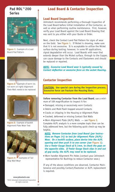
Figure 1: Example of a Load<br />
Board <strong>Pad</strong> Pattern<br />
Load Board & Contactor Inspection<br />
Load Board Inspection<br />
<strong>Johnstech</strong> recommends performing a thorough inspection of<br />
the Load Board before initial installation of the Contactor, as<br />
well as when performing routine maintenance. First, however,<br />
verify your Load Board against the Load Board Drawing that<br />
was sent to you either with your Quote or Order.<br />
Next, check the Contact Land <strong>Pad</strong> Pattern for signs of wear<br />
on the Gold. See Figure 1. If Nickel is showing, make sure<br />
that it is not excessive. It is acceptable to utilize the Nickel<br />
surface during testing; however, in some RF applications,<br />
signal degradation will occur. Load Boards with wear that<br />
extends deeper than the Nickel surface, through to the Copper,<br />
can cause damage to the Contacts and Elastomers and should<br />
be replaced or repaired.<br />
NOTE: Excessive Load Board wear is typically caused by<br />
Contact deflection or excessive force on the socket Housing.<br />
Figure 2: Example of worn (vs.<br />
not worn on right) Alignment<br />
Plate Wall; needs to be replaced<br />
Contactor Inspection<br />
CAUTION: Use special care during the inspection process.<br />
Excessive force can fracture the Housing Slots.<br />
Figure 3: Example of backlit<br />
Alignment Plate Wear Test<br />
Figure 4: Examples of Tail<br />
Stop Wall Wear<br />
Before removing Contactor from the Load Board, use a minimum<br />
of 10X magnification to inspect it for:<br />
· Damaged, missing or excessively worn Contacts<br />
· Debris and Mold Flash trapped around Contacts<br />
· Cracks or chipping in the Housing or Alignment Plate<br />
· Cracked, deformed or missing Contact Slot Walls<br />
· Worn Alignment Plate (ALPL) Walls — see Figure 2.<br />
Complete ALPL analysis is a more complex topic than can be<br />
fully addressed here, but the following quick check-up may be<br />
helpful.<br />
NOTE: Remove Contactor from Load Board (per instructions<br />
on Pages 14) to test for Alignment Plate (ALPL)<br />
Wear. On a backlit surface, place device into the ALPL<br />
opening and then push it to one corner (see Figure 3).<br />
Use a Feeler Gauge Stock of 0.1mm, to check the gaps on<br />
the opposite sides. If Feeler Gauge Stock slips in and out<br />
of gap easily, the ALPL may need to be replaced.<br />
· Worn handler Alignment Pin Holes (contact your <strong>Johnstech</strong><br />
representative for Bushings to reduce Contactor wear.)<br />
If any of the above conditions are observed, Contactor Maintenance<br />
and possibly Contact/Elastomer or ALPL replacement<br />
is required.<br />
www.johnstech.com<br />
©2010 <strong>Johnstech</strong> International Corporation<br />
All rights reserved.<br />
12