Installation and Operating Instructions - Crompton Instruments
Installation and Operating Instructions - Crompton Instruments
Installation and Operating Instructions - Crompton Instruments

You also want an ePaper? Increase the reach of your titles
YUMPU automatically turns print PDFs into web optimized ePapers that Google loves.
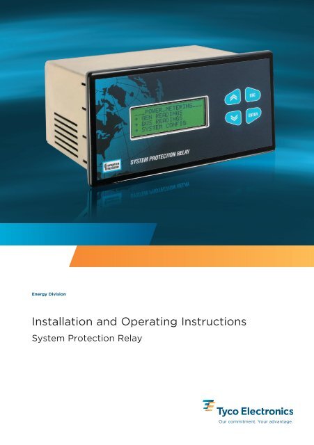
Energy Division<br />
<strong>Installation</strong> <strong>and</strong> <strong>Operating</strong> <strong>Instructions</strong><br />
System Protection Relay<br />
Our commitment. Your advantage.
System Protection Relay<br />
<strong>Installation</strong> & <strong>Operating</strong> Manual<br />
SPR – 013<br />
SPR – 014<br />
SPR Issue 6 03/08
Contents<br />
Page<br />
COPYRIGHT 6<br />
WARNINGS <strong>and</strong> Cautions 6<br />
INTRODUCTION<br />
General description 7<br />
INSTALLATION<br />
Unpacking 8<br />
Damage check 8<br />
Contents check 8<br />
Dimensions of the SPR 8<br />
Mounting notes 9<br />
Connecting the SPR 10<br />
Contrast adjustment 10<br />
Theory of operation <strong>and</strong> response time 11<br />
Watchdog relay 11<br />
Electromagnetic Compatability 11<br />
OPERATING INSTRUCTIONS<br />
General 12<br />
Default display 12<br />
Front panel controls 13<br />
Menu navigation buttons 13<br />
LCD contrast control 13<br />
Main menu 13<br />
Configuration menu 16<br />
Relays 16<br />
Range 16<br />
Time <strong>and</strong> date 16<br />
System tag names 18<br />
Display timout feature 19<br />
Configuring the user screen 20<br />
Viewing the user screen 21<br />
Saving relay setup 22<br />
Event log menu 22<br />
System configuration <strong>and</strong> relay status 23<br />
System configuration 23<br />
Bus readings 24<br />
Relay status 25<br />
Relay protective trip functions 26<br />
General 26<br />
Relay setting examples 27<br />
Setting up a relay contact 27<br />
Caption setting for relay configuration 29<br />
Logged 30<br />
Latched 30<br />
Alarm 30<br />
Failsafe 31<br />
Setting up an Alarm 34
Contents (Continued)<br />
Page<br />
Latching a Relay 38<br />
Testing relay latch functions 41<br />
Event log 43<br />
Logical operators 45<br />
Time over current relay 49<br />
Protective function detail 51<br />
Type 25 – Synchronising/synchronism-check 52<br />
Type 25D – Synchronising/synchronism-check with dead bus 53<br />
Type 27 – Under voltage 54<br />
Type 47 – Phase order (Phase sequence) 55<br />
Type 32R – Directional power (reverse) 55<br />
Type 47 – Voltage unbalance 56<br />
Type 51 – AC Time over current 57<br />
Time over current characteristics 58<br />
St<strong>and</strong>ard inverse curve 59<br />
Very inverse curve 60<br />
Extremely inverse curve 61<br />
Type 51V – AC Time over current with voltage restraint 62<br />
Type 51G – Time over current neutral ground fault check 63<br />
Type 59 – Over voltage 65<br />
Type 81O – Over frequency 66<br />
Type 81U – Under frequency 66<br />
Logical trip functions 67<br />
Type 40Q reverse Var 68<br />
Type 50 instantaneous over current 68<br />
Type 50N over neutral current 69<br />
Type 37 instantaneous under current 70<br />
Type 46 phase balance current 70<br />
Type 32O directional (forward) over power 71<br />
Power metering 72<br />
System configuration 72<br />
‘Generator’ checking 72<br />
Bus checking 74<br />
Password protection 75<br />
Introduction 75<br />
Using the password features 75<br />
<strong>Installation</strong> level password – Level 3 75<br />
Unlocking a password 76<br />
If a password has been lost or forgotten 77<br />
Changing a password 77<br />
Switching off password levels 77<br />
Engineering password – Level 2 77<br />
Operator level password – Level 1 78<br />
Lockout password – Level 0 78<br />
Password levels 79
Contents (Continued)<br />
Page<br />
RS485 digital output – MODBUS implementation 82<br />
Communication parameters 83<br />
Input registers 84<br />
Measurement registers 84<br />
Event log registers 85<br />
Holding registers 86<br />
System registers 86<br />
Relay registers 86<br />
Relay number 87<br />
Trip function 87<br />
Trip mode 87<br />
Trip status 88<br />
Trip parameters (1 to 6) 88<br />
RTC registers 88<br />
PRODUCT SPECIFICATION 89<br />
Inputs 89<br />
Outputs 89<br />
Display 90<br />
Auxiliary supply (24V) 90<br />
Realtime clock 91<br />
Measuring ranges 91<br />
Accuracy <strong>and</strong> resolution 91<br />
St<strong>and</strong>ards 92<br />
Environment 93<br />
Enclosure 93<br />
Serial Communications 94<br />
Specification approval 94<br />
Tables<br />
Fig<br />
1 Relay protective trip functions 20/42<br />
2 Measurement registers 71<br />
3 Event log registers 72<br />
4 Relay registers 73<br />
1 Dimensions of the SPR 7<br />
2 SPR back panel connections 8<br />
3 SPR electrical connections 9<br />
4 Time – current characteristic - st<strong>and</strong>ard inverse 50<br />
5 Time – current characteristic - very inverse 51<br />
6 Time – current characteristic - extremely inverse 52<br />
7 Time – current characteristic - long time st<strong>and</strong>by earth fault 64
COPYRIGHT<br />
The copyright in this document (including all information contained therein) is owned by<br />
CROMPTON INSTRUMENTS <strong>and</strong> must be used solely for the owner’s specified purposes.<br />
This document must not be copied or reproduced, nor divulged in whole or in part, without the<br />
owner’s written consent.<br />
WARNINGS<br />
1 The System Protection Relay is not intended to be used as a sole means of<br />
protection - good engineering practice dictates that any critical function be<br />
protected by two independent <strong>and</strong> diverse devices.<br />
2 In the interest of safety <strong>and</strong> functionality this product must be installed by<br />
qualified properly trained personnel abiding by local regulations.<br />
CAUTIONS<br />
3 Voltages dangerous to human life are present at some of the terminal<br />
connections of this unit. Ensure that all supplies are de-energised before<br />
attempting any connection or disconnection. External installations must be<br />
sufficient to protect human life <strong>and</strong> equipment under fault conditions.<br />
1 These products do not have internal fuses, therefore external fuses must<br />
be used for protection for safety under fault conditions.<br />
2 The current inputs of these products are designed for connection into<br />
systems via current transformers only.<br />
3 Never open-circuit the secondary winding of a current transformer. Always<br />
ensure that the power is disconnected before separating the current<br />
connector from SPR.<br />
4 Internal self-checking circuitry (watchdog) continuously monitors the<br />
operational state of the SPR, <strong>and</strong> operates a dedicated relay contact. If the<br />
Watchdog relay is in the ‘failed’ condition (not energised) all other relay<br />
contacts are forced to the de-energised condition.<br />
5 Operation outside specified limits may cause permanent damage or<br />
temporary disruption. For the latter case, normal operation may be<br />
restored by temporary disconnection of the auxiliary supply.<br />
6
INTRODUCTION<br />
Traditionally, each protection requirement in a switchboard or generating set has been met with<br />
individual protection relays. These relays have provided a reliable solution over many years, but<br />
with the high number of products required in some applications, this can require large amounts<br />
of space within a panel. The SPR combines all of the popular protection relay functions into one<br />
compact panel mounting product.<br />
GENERAL DESCRIPTION<br />
The System Protection Relay (SPR) is a microprocessor based unit which monitors three-phase<br />
voltage <strong>and</strong> current signals <strong>and</strong> a single-phase voltage input <strong>and</strong> provides a number of user<br />
definable relay outputs which perform protective functions (see OPERATING INSTRUCTIONS –<br />
Protective Functions).<br />
The unit is menu-controlled, which is achieved through the use of the front panel display <strong>and</strong><br />
four associated soft-touch controls (see OPERATING INSTRUCTIONS).<br />
Because the SPR measures all of the fundamental electrical parameters, the microprocessor can<br />
calculate other parameters <strong>and</strong> offer the user many more features <strong>and</strong> better protection.<br />
Also included are functions which allow logical relationships between the measured parameters<br />
<strong>and</strong> the output relays<br />
The main features of SPR are:<br />
●<br />
❥<br />
●<br />
●<br />
●<br />
●<br />
●<br />
●<br />
18 Protection Relay Functions<br />
9 Logical Relay Functions<br />
8 or 12 Change Over Relay (form C) Contacts<br />
Digital Technology<br />
Ease of Use<br />
Accurate Settings<br />
RS485 Modbus Communications<br />
Password Protection<br />
7
INSTALLATION<br />
UNPACKING<br />
Carefully unpack the unit <strong>and</strong> immediately carry out a damage <strong>and</strong> contents check. Retain the<br />
packing for possible future use, e.g. return to manufacturer for calibration.<br />
Damage check<br />
Carefully check that there are no signs of damage to the unit or associated connectors.<br />
If signs of damage are found, report these to your local sales office as soon as possible.<br />
Contents check<br />
Check the contents of the package agree with the following contents list:<br />
●<br />
One SPR unit.<br />
●<br />
<strong>Operating</strong> Manual.<br />
●<br />
Screw clamp electrical connectors<br />
●<br />
Panel mounting clamps<br />
DIMENSIONS OF THE SPR<br />
The case dimensions are shown in Fig 1.<br />
Fig 1 Dimensions of the SPR<br />
8
MOUNTING NOTES<br />
The SPR may be mounted in a panel of any thickness up to a maximum of 25mm (1").<br />
Mounting is by screw clamps. Consideration should be given to the space required behind the<br />
unit to allow for bends in the connection cables.<br />
As the enclosure conforms to IP54, the front panel is protected against ingress from water spray.<br />
Additional sealing to the panel may be obtained by the use of an optional gasket. The terminals<br />
at the rear of the case are not IP rated, <strong>and</strong> must be protected from liquids.<br />
The SPR should be mounted where the operating temperature is within the st<strong>and</strong>ard range of<br />
0°C to +50°C (+32°F to +122°F). Products are available with an extended operating temperature<br />
range of -20°C to +60°C (-4°F to +140°F) as a factory build option (specify when placing order).<br />
If the SPR is to be mounted in a location where it will be subjected to direct sunlight, ensure that<br />
any resulting temperature rise does not exceed the product’s operating temperature range.<br />
Vibration should be kept within specified operating limits. See full specification for details.<br />
Labels are affixed to the product to indicate connection information <strong>and</strong> electrical data.<br />
Connecting the SPR<br />
The SPR back panel is shown in Fig 2, <strong>and</strong> the connections are shown in Fig 3.<br />
Fig 2 SPR Back Panel Connections<br />
9
Connecting the SPR<br />
Wiring - Input connections are made directly to shrouded screw clamp terminals. Numbering is<br />
clearly marked on the case. Choice of cable should meet local regulations.<br />
●<br />
Voltage , Communications <strong>and</strong> Relay terminals will accept 0.2 to 2.5mm 2 (24 to12 AWG)<br />
diameter cables.<br />
●<br />
Terminals for current inputs will accept up to 0.2 to 4.0mm 2 (24 to 10 AWG)<br />
diameter cables.<br />
Auxiliary Supply - SPR should ideally be powered by a dedicated class 2 power supply. The SPR<br />
supply input must be protected by a 2 Amp HRC fuse. Ensure that the supply Voltage is within<br />
the working range for the auxiliary input. Refer to the products’ data label for input ratings.<br />
Fusing - In addition to the Auxiliary Supply, it is recommended that all voltage input lines are<br />
fitted with 1 amp quick blow fuses. For UL approved installations, all fuses must be UL<br />
listed parts.<br />
Earth/Ground Connections - The ground stud on the rear panel should be connected to a clean<br />
ground. For safety reasons, CT secondary connections should be grounded according to<br />
appropriate codes of practice.<br />
The electrical connections are shown in Fig 3.<br />
Model SPR-013<br />
Model SPR-014<br />
Note: Do not use terminal 10-12.<br />
Fig 3 SPR Electrical Connections<br />
Contrast adjustment<br />
Contrast adjustment is available via the front panel keys. See customising information. This may<br />
be necessary on installation to obtain the clearest display. Contrast is adjusted automatically to<br />
compensate for changes in ambient temperature. WARNING: There is a possibility of the display<br />
going blank if the manual contrast adjustment is set to extremes<br />
10
THEORY OF OPERATION AND RESPONSE TIME<br />
True RMS (Root Mean Square) measurements are calculated <strong>and</strong> displayed on the metering<br />
screen, <strong>and</strong> these measurements are also used to control the operation of the trip relays. Active<br />
powers are calculated directly by multiplication of Voltage <strong>and</strong> current. Reactive powers are<br />
calculated using a frequency corrected quarter-phase time delay method. SPR uses harmonic<br />
filtered waveform zero crossings to synchronize the sampling scheme to the input frequency. If<br />
the Voltage level on this input falls below the level at which the product can reliably determine<br />
the frequency, the default frequency is used. SPR samples each Voltage <strong>and</strong> current input,<br />
building up a 32 sample buffer, which means that distorted waveforms with content up to 15th<br />
harmonic will be accurately measured.<br />
The calculation of the RMS measurements <strong>and</strong> control of the trip relays takes approximately 90<br />
milliseconds, this is known as the "loop time". Once completed, the sampling / calculating /<br />
control process begins again. The typical response time for most trip functions is between 1 <strong>and</strong><br />
2 loop times.<br />
Where this differs for specific trip functions, further information can be found in the<br />
PROTECTIVE FUNCTION DETAIL section. The loop time can also be affected by intensive<br />
Modbus communications.<br />
WATCHDOG RELAY<br />
An internal watchdog circuit continuously monitors the operational state of the SPR, <strong>and</strong><br />
operates a dedicated relay contact. If the Watchdog relay is in the ‘failed’ condition (not<br />
energised) all other relay contacts are forced to the de-energised condition.<br />
ELECTROMAGNETIC COMPATIBILITY<br />
This unit has been designed to provide protection against EM (electro-magnetic) interference in<br />
line with requirements of EU <strong>and</strong> other regulations. Precautions necessary to provide proper<br />
operation of this <strong>and</strong> adjacent equipment will be installation dependent <strong>and</strong> so the following can<br />
only be general guidance:-<br />
●<br />
Avoid routing wiring to this unit alongside cables <strong>and</strong> products that are, or could be, a<br />
source of interference.<br />
• The auxuliary supply to the unit should not be subject to excessive interference. In some<br />
cases, a supply line filter may be required.<br />
• To protect the product against incorrect operation or permananet damage, surge<br />
transients must be controlled. It is good EMC practice to suppress differential surges to<br />
2kV or less at the source. The unit has been designed to automatically recover from<br />
typical transients, however in extreme circumstances it may be necessary to temporarily<br />
disconnect the auxiliary supply for a period of greater than 5 seconds to restore<br />
correct operation.<br />
• Screened communication <strong>and</strong> small signal leads are recommended <strong>and</strong> may be<br />
required. These <strong>and</strong> other connecting leads may require the fitting of RF suppression<br />
components, such as ferrite absorbers, line filters etc., if RF fields cause a problem.<br />
• It is good practice to install sensitive electronic instruments that are performing critical<br />
functions in EMC enclosures that protect against electrical interference causing a<br />
disturbance in function.<br />
11
OPERATING INSTRUCTIONS<br />
GENERAL<br />
Switch on the auxiliary supply. Following<br />
comprehensive diagnostic checks, <strong>and</strong><br />
once correct operation has been verified,<br />
the dedicated watchdog relay contacts<br />
energize to indicate system operational.<br />
Once this is complete, the start-up screen<br />
will be displayed for 5 seconds whilst the<br />
system performs its internal self-test. The<br />
software revision is also displayed.<br />
After approximately 5 seconds, the display<br />
changes to show the Relay Status Display.<br />
DEFAULT DISPLAY<br />
At any stage of operation, the display will<br />
revert back to this relay status screen if no<br />
front panel switches have been pressed for<br />
60 seconds. If no relay functions have been<br />
defined, the display will not indicate the<br />
presence of any physical relays.<br />
The default screen can be set to any of the<br />
viewable screens, as follows: Select the<br />
required displays screen, then press <strong>and</strong><br />
hold the UP <strong>and</strong> DOWN arrows buttons for<br />
several seconds. The LCD display will flash<br />
to indicate that the default screen has been<br />
changed.<br />
Changes to the default screen are not<br />
permanently stored. The default display is<br />
always the Relay Status screen when the<br />
unit is powered on.<br />
12
FRONT PANEL CONTROLS<br />
There are four ‘soft-touch’ control keys on the front panel; these are detailed below.<br />
Menu Navigation Keys<br />
These keys are used to<br />
move up or down the SPR<br />
menu, or to increase or<br />
decrease a numerical value.<br />
UP<br />
DOWN<br />
ESCAPE<br />
ENTER<br />
This key cancels an<br />
operation or quits the menu.<br />
Returns to previous level.<br />
This key is used to access<br />
the menu <strong>and</strong> to accept a<br />
data entry.<br />
LCD contrast control<br />
LCD contrast adjustment may be necessary upon installation to obtain the clearest display, <strong>and</strong><br />
may also be used to compensate for the viewing angle. The display contrast automatically<br />
compensates for ambient temperature changes.<br />
If the display has poor contrast or is not showing text, the contrast can be adjusted. While the<br />
RELAY STATUS screen is being displayed, press <strong>and</strong> hold the UP or the DOWN key on the unit<br />
front panel. The contrast is increased using the DOWN key, <strong>and</strong> decreased using the UP key.<br />
IMPORTANT: This adjustment only works when the RELAY STATUS screen is displayed. NOTE:<br />
The display may go blank if the adjustment is set to extremes.<br />
Any changes that you make will become the default setting.<br />
MAIN MENU<br />
Pressing the ESCAPE key will bring up the main menu display. You can navigate through the<br />
available selections using the UP <strong>and</strong> DOWN keys. The flashing cursor indicates the active line,<br />
<strong>and</strong> pressing ENTER on the active line takes you into that selected menu or function.<br />
(Note that in this manual, a white character on a black background indicates where the flashing<br />
cursor is located).<br />
13
NOTE: The available selections change, depending on the password control settings. See the<br />
password section for more details. With the password feature disabled, the following selections<br />
are available(in the order top to bottom of the display<br />
●<br />
RELAY STATUS – Indicates the<br />
condition of the physical relay<br />
contacts. As shipped from the<br />
factory, none of the relay functions<br />
are defined, so the display should be<br />
blank, as shown here.<br />
The status screen will indicate an<br />
appropriate ANSI caption or text label<br />
when a relay is in the tripped<br />
condition.<br />
Different symbols are used to identify<br />
the trip conditions:<br />
# The relay is tripped<br />
* Relay Alarm indication<br />
+ Acknowledged Alarm indication<br />
Different symbols are used to identify<br />
the trip conditions. The # symbol<br />
indicates that the relay is in the<br />
tripped condition, regardless of its<br />
energised or de-energised state.<br />
●<br />
RESET TRIPS – The Reset Trips<br />
feature is used to reset a latched<br />
relay contact, if this mode of<br />
operation has been configured.<br />
Relays can be reset individually. The<br />
display shows a list of<br />
all relays, what parameter is<br />
assigned to the relay, <strong>and</strong> allows<br />
analysis of the trip setting, although<br />
no changes can be made to the<br />
trip settings.<br />
14
●<br />
POWER METERING – Detailed menu<br />
to allow the checking of the electrical<br />
system measurements. For the<br />
Generator inputs, you can inspect the<br />
Voltage, current, power, VA, VAr,<br />
power factor, phase angle <strong>and</strong><br />
frequency. The Bus frequency <strong>and</strong><br />
phase difference can also be<br />
inspected.<br />
●<br />
EVENT LOG – If enabled, every time<br />
a relay trips, details of the event are<br />
stored in the Event History Log. This<br />
information can be viewed, but not<br />
changed. Allows analysis of previous<br />
trips, showing time <strong>and</strong> date of the<br />
event, plus the trip settings.<br />
●<br />
CONFIGURATION MENU - The<br />
Configuration Menu is used to set up<br />
the function of the relays, trip<br />
parameters <strong>and</strong> any other<br />
operational data. This entire menu<br />
can be password protected, or<br />
some features may not be visible.<br />
●<br />
PASSWORD – Up to four levels of<br />
password protection can be set up to<br />
prevent unauthorised operation of<br />
the product.<br />
●<br />
VERSION – The firmware version can<br />
be inspected from this screen.<br />
15
CONFIGURATION MENU<br />
All aspects of product operation are defined from this configuration menu. Certain comm<strong>and</strong>s<br />
can be locked by password, <strong>and</strong> may not be accessible. In some cases, the configuration menu<br />
is not even available<br />
Relays<br />
The relay configuration menu forms<br />
defined product functionality. Because<br />
the product is so flexible, this is best<br />
demonstrated in the form of practical<br />
examples. Please see the application<br />
notes for more details, .<br />
Range<br />
The range menu allows primary PT <strong>and</strong><br />
CT values to be entered, if required.<br />
Press ENTER to edit a value.<br />
Only enter a primary value. Secondary<br />
values are fixed in hardware – see<br />
product labelling for details.<br />
Time <strong>and</strong> Date<br />
The product contains a real time clock to<br />
maintain accurate time <strong>and</strong> date stamps<br />
for the event history log. The clock has<br />
battery backup to maintain accuracy<br />
whenever the product is powered down.<br />
You may need to alter the time setting to<br />
reflect daylight saving, or to suit the time<br />
zones in different locations. Press ENTER<br />
to start editing the time.<br />
The clock calendar will allow for leap<br />
years <strong>and</strong> the calendar is powered from<br />
the auxiliary supply when the SPR is in<br />
use. If power is removed, the clock<br />
calendar draws its power from an<br />
internal lithium battery. The battery has a<br />
life of 3 years when in use without the<br />
SPR being powered; therefore the actual<br />
life of the battery will exceed this figure<br />
depending upon the use the SPR<br />
receives.<br />
16
To change the date <strong>and</strong>/or the time,<br />
proceed as follows: Press the DOWN key<br />
to highlight the Time <strong>and</strong> Date option.<br />
Press ENTER.<br />
The display shown opposite appears.<br />
(The time shown here is for illustration<br />
only).<br />
The time clock format is 24 hour, <strong>and</strong><br />
the hour, minutes <strong>and</strong> seconds can be<br />
modified as required. The time will<br />
constantly update, thus the figures will<br />
always be changing.<br />
Use the UP/DOWN keys to select the<br />
parameter to be changed, press ENTER<br />
to highlight the parameter value (the<br />
cursor will flash the value)<br />
Use the UP/DOWN buttons to change<br />
the value; press ENTER to accept or ESC<br />
if an incorrect value has been set.<br />
Once all the Time parameters are<br />
correct, press ESC to return to the Time<br />
<strong>and</strong> Date menu.<br />
If the date is not to be changed, press<br />
ESC to quit this menu.<br />
If the date is to be changed, use the<br />
DOWN key to highlight Date <strong>and</strong> press<br />
ENTER. The screen opposite will be<br />
displayed. Use the UP/DOWN keys to<br />
select the parameter to be changed,<br />
press ENTER to highlight the parameter<br />
value (the cursor will flash the value)<br />
Use the UP/DOWN buttons to change<br />
the value; press ENTER to accept or ESC<br />
if an incorrect value has been set.<br />
Once all the Date parameters are correct,<br />
press ESC 3 times to return to the Main<br />
Menu.<br />
Note: The date format can be changed<br />
from DD/MM/YY to MM/DD/YY in the<br />
DISPLAY menu. Time <strong>and</strong> date can also<br />
be adjusted via RS485 MODBUS comms.<br />
17
System Tag Names<br />
The default system tag names are GEN <strong>and</strong> BUS, useful for Generator systems. The tag names<br />
can be changed to suit the different product applications, <strong>and</strong> a choice of 16 pre-defined names<br />
are available.<br />
Enter the CONFIGURATION menu, <strong>and</strong><br />
select the DISPLAY SETUP menu.<br />
Scroll down to view the default settings<br />
for Input1 <strong>and</strong> Input2<br />
To edit a tag name, press Enter <strong>and</strong> the<br />
use the Up/Down arrows to scroll<br />
through the selection list. The following<br />
tag names are available: Gen, Bus, Bus1,<br />
Bus2, Main, Gen1, Gen2, Tran, Motr,<br />
Brkr, Feed, Aux1, Aux2, Aux3, Aux4,<br />
Aux5<br />
Press ENTER to select the desired name.<br />
18
Display Timeout Feature<br />
In some applications it is a requirement<br />
that there are no lamps on the control<br />
panel unless a fault or trip condition<br />
exists. The LCD display backlight can be<br />
switched off via the DISPLAY SETUP<br />
menu, located within the Configuration<br />
menu.<br />
Scroll down to ‘Backlight’ <strong>and</strong> press<br />
ENTER.<br />
Use the Up/Down arrows to switch the<br />
LCD Backlight On or Off.<br />
Once switched off, the backlight remains<br />
off unless a front panel button is<br />
pressed, or an alarm condition exists (if<br />
feature is enabled) in which case the<br />
backlight will flash to attract attention.<br />
For changes to the backlight setting to<br />
take effect, wait for the display to revert<br />
to the default screen, or power cycle the<br />
instrument.<br />
19
Configuring the User Screen<br />
The default screen can be configured as<br />
a user screen, where the four line display<br />
can be customised to indicate four<br />
measurement values of a possible 37<br />
electrical system measurements. This<br />
feature is accessed via the Configuration<br />
menu.<br />
Press Enter on start editing the<br />
individual display lines.<br />
Use the Up/Down keys to scroll through<br />
the available parameters, <strong>and</strong> press<br />
Enter to make the selection. The<br />
following measurements are available<br />
for display:<br />
None, VL1, VL2, VL3, I1, I2, I3, W1, W2,<br />
W3, VA1, VA2, VA3, VAr1, VAr2, VAr3,<br />
PF1, PF2, PF3, PA1, PA2, PA3, Vavg, Iavg,<br />
Isum, Wsum, VAsum, VArsum, PFsum,<br />
PAsum, Freq, VL1L2, VL2L3, VL3L1, In,<br />
Freq2, Angle, Ig<br />
Scroll Down to view or edit the settings<br />
for Line 4.<br />
20
Viewing the User Screen<br />
Select the Power Metering screen <strong>and</strong> choose the User Screen option. The customised screen<br />
will be displayed until the one-minute timeout restores the default screen again. If a permanent<br />
user screen display is required, you can make it the default screen as follows: With the User<br />
Screen displayed, press <strong>and</strong> hold the Up <strong>and</strong> Down buttons. After 5 seconds, the display will<br />
flash to confirm that the default has been changed.<br />
To cancel the user screen <strong>and</strong> change the default display back to the Relay Status display, either<br />
a) re-configure all four parameters to NONE, or b) select the Relay Status screen then press <strong>and</strong><br />
hold the Up <strong>and</strong> Down buttons until the display flashes.<br />
If the user screen has been configured,<br />
you can select it from the Power Metering<br />
menu.<br />
21
Saving Relay Setup<br />
When changes have been made to any parameter in the configuration menu, the save comm<strong>and</strong><br />
must be used to permanently store the new settings.<br />
If changes have not been saved, they will<br />
be lost when the product is powered<br />
down. Press ENTER to select the Save<br />
comm<strong>and</strong>.<br />
Press ENTER again, <strong>and</strong> you will be<br />
prompted with SURE. If you are sure<br />
you wish to save the changes, press<br />
ENTER again, otherwise, press ESC to<br />
cancel the save operation.<br />
Event Log Menu<br />
Every time a relay trips, event details can be recorded in the event log with a time <strong>and</strong> date<br />
stamp. This is useful for analysing the system problems, <strong>and</strong> because events are recorded to a<br />
time resolution of 100ms, the sequence of trip events can be studied. The date <strong>and</strong> time are<br />
maintained by an internal real time clock with battery backup. The product stores details of the<br />
last fifty trip events, <strong>and</strong> if more trips occur, the oldest records are deleted so that new<br />
information can be recorded.<br />
IMPORTANT: Event information will be<br />
lost if the product is powered down. The<br />
event log will also be cleared if the relay<br />
configuration has been altered in the<br />
configuration menu.<br />
The most recent trip is held in the highest<br />
event record. In this example, Relay 1<br />
tripped on March 14, 2004 at 10:22 am,<br />
because of an under voltage condition.<br />
You can view the trip settings using the<br />
UP/DOWN keys, but no changes can be<br />
made. To view the other event<br />
information, press ENTER to edit the<br />
event number, then use the UP/DOWN<br />
keys to step through them.<br />
If no trip events have taken place since<br />
the last power-down, you will find blank<br />
records.<br />
22
SYSTEM CONFIGURATION AND RELAY STATUS<br />
When the SPR is initially installed, the relay status will display a blank screen since system has<br />
not been configured for your application <strong>and</strong> the relay parameters have not been set up. Relay<br />
parameter settings will depend upon your configuration.<br />
System configuration<br />
All aspects of product operation are defined from this configuration menu. Certain comm<strong>and</strong>s<br />
can be locked by password, <strong>and</strong> be hidden. In some cases, the configuration menu is not even<br />
available. The system configuration parameters consist of<br />
●<br />
System Voltage<br />
●<br />
System Current (Amps)<br />
●<br />
System Type<br />
To check your system configuration, proceed as follows:<br />
Return to the Main Menu by pressing<br />
ESC as required.<br />
Use the DOWN key to highlight POWER<br />
METERING <strong>and</strong> press ENTER.<br />
Use the DOWN button to highlight<br />
SYSTEM CONFIG <strong>and</strong> press ENTER. The<br />
system configuration display will appear<br />
on the screen<br />
The Primary System Voltage <strong>and</strong> Primary<br />
System Current (Amps) can be set to suit<br />
your usage; System Power is calculated<br />
according to these values.<br />
The System Type is factory pre-set to 3-<br />
phase 3 wire or 4 wire, <strong>and</strong> can not be<br />
changed.<br />
23
Default settings are the factory build<br />
voltage <strong>and</strong> current for the product. If<br />
connections are via P.T. or C.T. then you<br />
will need to change the system settings.<br />
Proceed as follows:<br />
Return to the Main Menu by pressing<br />
ESC as required.<br />
Use the DOWN key to highlight<br />
CONFIGURATION <strong>and</strong> press ENTER.<br />
Use the DOWN key to highlight RANGE<br />
<strong>and</strong> press ENTER.<br />
The range display will appear on the<br />
screen<br />
Position the first parameter under the<br />
flashing cursor using the UP/DOWN<br />
keys. Press ENTER to select the<br />
parameter value <strong>and</strong> amend the value<br />
using the UP/DOWN keys.<br />
Press ENTER if the value is correct, or<br />
ESC if an error has been made, <strong>and</strong><br />
change the other parameter if necessary.<br />
Range changes take effect as they are<br />
entered <strong>and</strong> do not need to be saved<br />
explicitly.<br />
Press ESC to return to the main menu.<br />
Bus Readings<br />
If connected, check that the frequency is<br />
correct.<br />
24
Relay status<br />
When the SPR is initially installed, the trip function (parameter to be monitored) of each relay<br />
has not been set, <strong>and</strong> the display will be blank. The number of, <strong>and</strong> the setting for each, relays is<br />
dependent upon your requirement, up to a maximum of 12 relays.<br />
Each relay can be set to monitor any one of 27 protective (electrical <strong>and</strong> logical) trip functions;<br />
these are listed in Table 1. (The ANSI Number refers to the American National St<strong>and</strong>ards<br />
Institute listing).<br />
Table 1 Relay Protective Trip Functions<br />
ANSI Type No Menu Description Description<br />
Unused<br />
The relay is disabled<br />
59 Over Volts Over Voltage Relay<br />
27 Under Volts Under Voltage Relay<br />
81O Over Freq Over Frequency Relay<br />
81U Under Freq Under Frequency Relay<br />
50 Over Amps Instantaneous Over Current Relay<br />
37 Under Amps Instantaneous Under Current Relay<br />
50N Over Amps Instantaneous Over Neutral Current Relay<br />
32R Reverse Pwr Reverse Power Relay<br />
32O Over Power Forward Power Relay<br />
40Q Reverse VAr Reverse VAr Relay<br />
47 UnBal Volts Unbalanced Voltage Relay<br />
46 UnBal Amps Unbalanced Current Relay<br />
51V I/T+V.R. Time Over Current with Voltage Restraint Relay<br />
51 I/T Time Over Current Relay<br />
51G Gnd Fault Neutral Ground Fault Relay<br />
25 Sync Synchronism Check Relay<br />
25D Sync+DB Synchronism Check with Dead Bus Relay<br />
47 Phase Order Phase Sequence Relay<br />
Logical AND<br />
Logical OR<br />
Logical NAND<br />
Logical NOR<br />
Logical XOR<br />
Logical Vote<br />
Logical Disc<br />
Alarm<br />
Unack Alarm<br />
Will trip if all 3 inputs are tripped<br />
Will trip if any input is tripped<br />
Will trip unless all 3 inputs are tripped<br />
Will trip if any input is not tripped<br />
Will trip if the 3 inputs are not in the same state<br />
Will trip if at least 2 inputs are tripped<br />
Will trip if there is a discrepancy between inputs<br />
Will trip if an alarm situation exists<br />
Will trip if an alarm has not been acknowledged<br />
Note: Although the number of physical relays will be 8 or 12, the SPR will allow you to set up to<br />
16. These ‘virtual’ relays operate normally, although there is no physical relay contact. These<br />
can typically be used for marshalling purposes.<br />
25
RELAY PROTECTIVE TRIP FUNCTIONS<br />
General<br />
This section gives details on the setting of Relays in general, followed by some application<br />
examples.<br />
At the initial Screen, scroll down to<br />
CONFIGURATION. Press ENTER to bring<br />
up the menu shown opposite.<br />
Press ENTER to bring up the Relay<br />
parameters, opposite.<br />
(The parameters shown are for example<br />
only).<br />
To change the Relay number, press<br />
Enter <strong>and</strong> the cursor will move to the<br />
number. Use the UP/DOWN keys to<br />
scroll to the required Relay number.<br />
Press ENTER to accept or ESC to reject.<br />
Use the DOWN key to select TRIP <strong>and</strong><br />
press ENTER to highlight the parameter<br />
ANSI number or function (cursor moves<br />
to the right).<br />
Use the UP/DOWN keys to scroll to the<br />
required function; press ENTER to<br />
accept or ESC to reject.<br />
Each trip function has its own set of<br />
parameters. Use the UP/DOWN keys<br />
scroll down <strong>and</strong> review or change the<br />
parameter settings as required.<br />
Some parameters have YES / NO<br />
choices, while others require numerical<br />
input.<br />
When all settings are correct, press ESC<br />
once to return to CONFIG or twice to<br />
return to the Main Menu.<br />
26
RELAY SETTING EXAMPLES<br />
To show how to configure the system <strong>and</strong> the relays, some examples are included here.<br />
Setting up a relay contact<br />
This example will demonstrate how to<br />
configure one relay contact inside the<br />
SPR to perform an over-voltage function.<br />
You will be setting Relay 1 to operate as<br />
Over Voltage, tripping at 120 Volts.<br />
Switch on the auxiliary supply. The startup<br />
screen (opposite) will be displayed for<br />
5 seconds.<br />
The display then defaults to the Relay<br />
Status Display, shown opposite.<br />
Note: When no front panel switches have<br />
been pressed for 60 seconds, the display<br />
will revert to the Relay Status display.<br />
If no Relay functions have been set, this<br />
display may be blank.<br />
If necessary, set up the unit contrast (see<br />
LCD contrast control).<br />
Press the ESC key to bring up the Main<br />
Menu.<br />
Using the DOWN key, scroll until<br />
CONFIGURATION is under the cursor.<br />
Press ENTER <strong>and</strong> the configuration<br />
screen will be displayed.<br />
27
Press ENTER to bring up the Relay setup<br />
screen.<br />
If Relay 1 is not displayed, press ENTER<br />
to move the cursor to select the relay<br />
number; the relay selected can be<br />
changed using the UP/DOWN keys.<br />
When 1 is displayed, press ENTER<br />
to accept.<br />
The function required for this example is<br />
under voltage (UNDER VOLTS). Move<br />
the cursor onto the Trip line <strong>and</strong> press<br />
ENTER.<br />
Use the UP/DOWN keys to select the<br />
UNDER VOLTS function. (The ANSI<br />
number will also be displayed in this<br />
example, see Table 5).<br />
When the correct function is displayed,<br />
press ENTER.<br />
28
CAPTION SETTING FOR RELAY CONFIGURATION<br />
By default, the caption is the ANSI<br />
number or logical name for the selected<br />
relay function. If a different caption is<br />
required, you can edit the displayed<br />
caption name to any 4-character<br />
combination to suit the application.<br />
Scroll down to the ‘caption’ line<br />
Press ‘Enter’ <strong>and</strong> the cursor will move<br />
across to the caption text field<br />
Use the Up/Down arrow keys to change<br />
the highlighted character. Permissible<br />
characters are alphabetic, numeric or<br />
symbol are:<br />
{|} !“#$%&’()*+,-./:;@[]^_<br />
0123456789<br />
ABCDEFGHIJKLMNOPQRSTUVWXYZ<br />
abcdefghijklmnopqrstuvwxyz<br />
Press ‘Enter’ to select the next character<br />
Continue to edit the remaining<br />
characters, until all four digits have<br />
been entered.<br />
29
Logged<br />
SPR can record the time date of trip<br />
events. The configuration setting for each<br />
relay allows the ‘Logged’ selection to be<br />
set to Y (yes) or N (no). If Logging is<br />
enabled, then every trip event for that<br />
relay will be recorded in the log. Press<br />
‘Enter’ to select the Logged function,<br />
then use the Up/Down keys to change<br />
between Y <strong>and</strong> N.<br />
Latched<br />
The relay-latching feature can be<br />
switched on or off as required. When<br />
enabled, <strong>and</strong> a trip condition is detected,<br />
the relay will change state <strong>and</strong> stay in<br />
this condition until it is specifically reset.<br />
This is typically used to lock out further<br />
operation of equipment after a fault has<br />
been detected. Note that setting the<br />
Latched operation may be undesirable for<br />
some trip functions. Press ‘Enter’ to select<br />
the Latched function, then use the<br />
Up/Down keys to change between Y <strong>and</strong><br />
N.<br />
Alarm<br />
The alarm function, when enabled, will<br />
cause the LCD display to flash (to attract<br />
attention) when the relay trips. Even if<br />
the relay is reset (when the trip condition<br />
goes away) the display will continue to<br />
flash. The alarm must be acknowledged<br />
by pressing a key. Press ‘Enter’ to select<br />
the Alarm function, then use the<br />
Up/Down keys to change between Y <strong>and</strong><br />
N. This topic is covered in more detail<br />
within the examples section.<br />
30
Fail Safe<br />
The default relay operation is failsafe,<br />
meaning the relay contact is energised in<br />
the ‘normal’ condition <strong>and</strong> de-energised<br />
in the ‘tripped’ condition. Setting Failsafe<br />
to ‘N’ will change the default relay state<br />
to de-energised, so the relay will energize<br />
on trip. Press ‘Enter’ to select the Failsafe<br />
function, then use the Up/Down keys to<br />
change between Y <strong>and</strong> N.<br />
Select TripPoint <strong>and</strong> press ENTER. The<br />
value displayed is in real units – in this<br />
case, AC Volts. Use the up/ down keys to<br />
adjust the trip voltage to 100. When<br />
finished, press ENTER.<br />
DIFF means differential or hysteresis.<br />
This is used to give stability to the relay,<br />
<strong>and</strong> to stop it from nuisance tripping.<br />
When the measured signal level is very<br />
close to the trip point, electrical noise<br />
<strong>and</strong> spikes can lead to spurious<br />
energize/de-energize relay operations<br />
when the level momentarily exceeds the<br />
trip point, then returns to its normal<br />
level. The DIFF setting increases the<br />
threshold between trip <strong>and</strong> reset points<br />
to add stability to noisy systems. The<br />
parameter is a real unit – in this case, AC<br />
volts. Set the value to 3 volts.<br />
Note: Too little hysteresis may lead to nuisance tripping, whilst too much hysteresis<br />
may mean the relay will not drop back in after a trip. Hysteresis settings can cause<br />
problems if set unnecessarily high. The default setting is 1% of the nominal range, but<br />
this can be increased as required for ‘noisy’ signals.<br />
31
Finally, the time delay can be set. The<br />
number is adjustable between 0 <strong>and</strong> 30<br />
seconds in steps of 0.1 second. Use the<br />
arrow keys to change the value, <strong>and</strong><br />
press ENTER to accept. Set the value to 1<br />
second. The time delay is a qualification<br />
period for a trip condition. The trip<br />
condition must exist for the entire<br />
duration of the delay before the relay will<br />
change state.<br />
Now the relay setup is complete. Press<br />
ESC once to quit the relay setup menu<br />
<strong>and</strong> return to the Configuration menu.<br />
To save the configuration changes for<br />
future use, scroll down the Configuration<br />
menu <strong>and</strong> select the SAVE RELAY<br />
SETTINGS option <strong>and</strong> press ENTER. The<br />
settings will be stored in non-volatile<br />
memory, <strong>and</strong> will be automatically<br />
recalled every time the product is<br />
switched on.<br />
Press ESC three (3) times to return to the<br />
Main Menu.<br />
Press ENTER to view the Relay Status<br />
Display.<br />
Summary of the new relay settings<br />
You should now have set the product as<br />
follows:<br />
Relay 1<br />
Trip Under Volts 27<br />
Caption 27<br />
Logged<br />
N<br />
Latched<br />
N<br />
Alarm<br />
N<br />
Failsafe<br />
Y<br />
TripPoint<br />
100.0 V<br />
Diff<br />
3.0 V<br />
TimeDelay<br />
1.0 Sec<br />
32
Testing Relay 1<br />
Now you are ready to test the relay<br />
contact function. This example assumes<br />
a nominal 120V product.<br />
With no measuring signal input, the relay<br />
should be tripped (no Voltage ). Confirm<br />
that Relay 1 contact is de-energised.<br />
Apply a three-phase, variable, AC voltage<br />
source to the input, initially set to 120V.<br />
Now decrease the voltage slowly.<br />
Confirm Relay 1 contact is energised.<br />
Note that the SPR is checking each phase<br />
for a voltage less than 100 V.<br />
Once the voltage falls below 100 V, the<br />
relay will trip, <strong>and</strong> the status display will<br />
indicate as shown opposite.<br />
The # symbol indicates that Relay 1 has<br />
tripped (<strong>and</strong> is still tripped).<br />
Confirm that Relay 1 contact is now deenergised.<br />
Now increase the voltage until the # sign<br />
disappears. This should be a level of 103<br />
V (which is the trip setting of 100 V plus<br />
the differential of 3 V)<br />
The relay will change state, back to<br />
energised.<br />
33
Setting up an Alarm<br />
This example will demonstrate how to configure relay contacts inside the SPR to cause an alarm<br />
condition when a trip is detected. You will be setting Relay 1 to operate as Over Voltage,<br />
tripping at 120 V (this follows on from the previous example, Setting up a relay contact).<br />
Start from the Relay Status Display<br />
shown.<br />
Press the ESC button to bring up the<br />
Main Menu. A flashing cursor will appear<br />
on the active line.<br />
Using the DOWN key, scroll until<br />
CONFIGURATION is under the cursor.<br />
Press ENTER <strong>and</strong> the configuration<br />
screen will be displayed.<br />
Press ENTER to bring up the relay setup<br />
screen.<br />
34
If Relay 1 is not displayed (it could<br />
default to another relay), press ENTER to<br />
move the cursor to select the relay<br />
number; the relay selected can be<br />
changed using the UP/DOWN keys.<br />
When 1 is displayed, press ENTER to<br />
accept.<br />
Then change the trip function to Over<br />
Volts.<br />
Using the UP/DOWN keys, scroll down<br />
until Alarm is under the cursor, then<br />
press ENTER. Change the function to Y<br />
(Yes) using the UP key. Then change the<br />
trip point to 120V. Change the Diff<br />
setting to 3.0V <strong>and</strong> delay to 1.0 seconds.<br />
Now the relay setup is complete. Press<br />
ESC once to quit the relay setup menu<br />
<strong>and</strong> return to the Configuration menu.<br />
To save the configuration changes, scroll<br />
down the Configuration menu <strong>and</strong> select<br />
the SAVE option <strong>and</strong> press ENTER. The<br />
settings will be stored in non-volatile<br />
memory, <strong>and</strong> will be automatically<br />
recalled every time the product is<br />
switched on.<br />
Press ESC three (3) times to return to the<br />
Main Menu.<br />
Press ENTER to view the Relay Status<br />
Display.<br />
35
Summary of the new relay settings<br />
You should now have set the product as follows:<br />
Relay 1<br />
Trip Over Volts 59<br />
Caption 59<br />
Logged<br />
N<br />
Latched<br />
N<br />
Alarm<br />
Y<br />
Failsafe<br />
Y<br />
TripPoint 120.0<br />
Diff<br />
3.0 V<br />
TimeDelay<br />
1.0 Sec<br />
Testing Relay 1<br />
Now you are ready to test the relay Alarm function.<br />
With no measuring signal input, the relay should not be tripped. Confirm that Relay 1 contact is<br />
energised (Failsafe)<br />
Apply a variable AC voltage source to the input, <strong>and</strong> slowly increase the voltage.<br />
Note that the SPR is checking each phase for a voltage greater than 120 V.<br />
Once the voltage exceeds 120 V, the<br />
relay will trip, <strong>and</strong>, because the alarm<br />
function is enabled on Relay 1, the LCD<br />
backlight will flash on <strong>and</strong> off to attract<br />
attention.<br />
The * symbol indicates that Relay 1<br />
caused the alarm condition.<br />
Now decrease the voltage below 117 V.<br />
The relay contacts will reset, but the<br />
display will continue to flash. You must<br />
acknowledge the alarm to stop the<br />
display flashing, by pressing the<br />
Enter button.<br />
36
Increase the voltage source again until<br />
the relay trips. The display will start to<br />
flash. Now press Enter to acknowledge<br />
the alarm. The display indicates that you<br />
have acknowledged the condition, but<br />
continues to flash slowly to indicate the<br />
relay is still in the tripped condition. The<br />
+ symbol also indicates this.<br />
Now decrease the voltage below 117 V.<br />
The relay contacts will reset, the status<br />
display will clear, <strong>and</strong> the display will<br />
stop flashing.<br />
Note on Alarms: You can set up a<br />
relay contact to trip if any relay has<br />
caused an alarm condition. This can be<br />
used as a common alarm signal, or used<br />
to control an external sounder (horn)<br />
etc. Additionally, a relay can be<br />
configured to trip only if the alarm has<br />
not been acknowledged.<br />
37
Latching a Relay<br />
This example demonstrates Relay 1 latching when a trip is detected. Relay 1 is configured to<br />
Over Voltage, tripping at 120 V (from the examples Setting up a relay contact <strong>and</strong> Setting up an<br />
Alarm).<br />
Start from the Relay Status display<br />
shown.<br />
Press the ESC button to bring up the<br />
Main Menu, a flashing cursor will appear<br />
on the active line.<br />
Using the DOWN key, scroll until<br />
CONFIGURATION is under the cursor.<br />
Press ENTER <strong>and</strong> the configuration<br />
screen will be displayed.<br />
38
Press ENTER to bring up the relay setup<br />
screen.<br />
If Relay 1 is not displayed, press ENTER<br />
to move the cursor to select the relay<br />
number; the relay selected can be<br />
changed using the UP/DOWN keys.<br />
When 1 is displayed, press ENTER to<br />
accept.<br />
Using the UP/DOWN buttons, scroll<br />
down until Latch is under the cursor,<br />
then press ENTER. Change the function<br />
to Y (Yes) using the UP button.<br />
Switch the Alarm function off.<br />
Now the relay setup is complete. Press<br />
ESC once to quit the relay setup menu<br />
<strong>and</strong> return to the Configuration menu.<br />
To save the configuration changes for<br />
future use, scroll down the Configuration<br />
menu <strong>and</strong> select the SAVE option <strong>and</strong><br />
press ENTER. The settings will be stored<br />
in non-volatile memory, <strong>and</strong> will be<br />
automatically recalled every time the<br />
product is switched on.<br />
39
Press ESC three (3) times to return to the<br />
Main Menu.<br />
Press ENTER to view the Relay Status<br />
Display.<br />
Summary of the new relay settings<br />
You should now have set the product as follows:<br />
Relay 1<br />
Trip Over Volts 59<br />
Caption 59<br />
Latched<br />
Y<br />
Alarm<br />
N<br />
Failsafe<br />
Y<br />
TripPoint 120.0<br />
Diff<br />
3.0 V<br />
TimeDelay<br />
1.0 Sec<br />
40
Testing Relay 1 Latch function<br />
Now you are ready to test the relay Latch<br />
function.<br />
With no measuring signal input, the relay<br />
should not be tripped. Confirm that Relay<br />
1 contact is energised (because we set<br />
Fail Safe to Y).<br />
Apply a variable AC voltage source to<br />
the input, <strong>and</strong> slowly increase the<br />
voltage.<br />
Note that the SPR is checking each phase<br />
for a voltage greater than 120 V.<br />
Once the voltage exceeds 120 V, the<br />
relay will trip, <strong>and</strong> the relay status<br />
display will indicate as shown.<br />
The # symbol indicates that Relay 1 has<br />
tripped (<strong>and</strong> is still tripped).<br />
Confirm that Relay 1 contact is now deenergised.<br />
Now decrease the voltage below 117 V.<br />
The # remains on the display, <strong>and</strong> the<br />
contacts stay de-energised. The relay has<br />
latched <strong>and</strong> must be manually reset.<br />
Press the ESC button to bring up the<br />
main menu.<br />
Select the RESET TRIPS option <strong>and</strong> press<br />
ENTER.<br />
41
Line 1 shows allows you to select the<br />
appropriate relay. Press ENTER <strong>and</strong> use<br />
the up/down arrow keys to select a<br />
different relay, <strong>and</strong> press ENTER to<br />
select it.<br />
The second line of the display shows<br />
the function assigned to each relay. This<br />
is for information only, <strong>and</strong> cannot be<br />
changed. Line 4 indicates that the relay<br />
is tripped.<br />
Press the DOWN key to place the cursor<br />
over Tripped.<br />
Press ENTER, edit the trip flag to N (NO)<br />
using the DOWN key, then press ENTER<br />
to accept the change.<br />
The relay is now reset.<br />
Confirm that Relay 1 contact is now<br />
energised<br />
Exit the Reset Menu by pressing ESC,<br />
<strong>and</strong> go back into the Relay Status<br />
screen.<br />
The asterisk has disappeared.<br />
Note:<br />
If the trip condition still exists, the<br />
latched relay cannot be reset.<br />
42
Event Log<br />
SPR can record the time date of trip events. The configuration setting for each relay allows the<br />
‘Logged’ selection to be set to yes or no. If Logging is enabled, then every trip event will be<br />
recorded.<br />
Edit relay 1 settings as follows, changing Logged to Y <strong>and</strong> Latched to N.<br />
Relay 1<br />
Trip Over Volts 59<br />
Caption 59<br />
Logged<br />
Y<br />
Latched<br />
N<br />
Alarm<br />
N<br />
Failsafe<br />
Y<br />
TripPoint<br />
120.0 V<br />
Diff<br />
3.0 V<br />
TimeDelay 1.0 Sec<br />
Apply a variable AC voltage source to the input, <strong>and</strong> increase the voltage until the relay trips.<br />
The status display will indicate 59# as normal. Now reduce the voltage until the relay resets.<br />
Wait several seconds, then increase the voltage to cause another trip. This exercise should<br />
have made two entries into the event log.<br />
The event log can be accessed from the<br />
main menu<br />
Scroll down until the cursor highlights<br />
the event log entry.<br />
Press ENTER to access the sub-menu.<br />
There are three entries. Select ‘VIEW.’<br />
43
The event log contains data for up to<br />
50 trip events, stored in time order,<br />
oldest first. The event record indicates<br />
the date <strong>and</strong> time of the trip, the relay<br />
number, <strong>and</strong> the trip function type.<br />
You can scroll down to review the<br />
relay settings.<br />
To view other events, select the event<br />
number <strong>and</strong> use the Up/Down arrows<br />
to scroll through the event log entries.<br />
Press ESCAPE to quit the VIEW menu.<br />
Select SUMMARY <strong>and</strong> press ENTER.<br />
The event log summary is displayed.<br />
Use the Up/Down arrows to scroll<br />
through the summary information for<br />
each log entry.<br />
To clear the event log, select the<br />
CLEAR menu <strong>and</strong> press ENTER.<br />
The confirmation screen prevents<br />
accidental deletion of the log. Press<br />
ENTER to confirm the clear operation,<br />
or press ESCAPE to quit.<br />
Note: The event log data is stored only<br />
whilst the auxiliary supply is present.<br />
Note: The event log stores the most<br />
recent 50 trip events. If more than 50<br />
events are logged, the older entries are<br />
deleted.<br />
44
Logical operators<br />
This example demonstrates how the logical operators can be used. You will be setting up Relay<br />
2 to trip at the same time as Relay 1 trips, effectively making a double-pole relay. Relay 1 is<br />
configured to Over Voltage, tripping at 120 Volts.<br />
Start from the Relay Status screen.<br />
Press ESC to bring up the Main Menu A<br />
flashing cursor will appear on the active<br />
line.<br />
Using the DOWN key, scroll until<br />
CONFIGURATION is under the cursor.<br />
Press ENTER <strong>and</strong> the configuration<br />
screen will be displayed.<br />
Press ENTER again to bring up the relay<br />
setup screen.<br />
45
If Relay 2 is not displayed, press ENTER<br />
to move the cursor to select the relay<br />
number; the relay selected can be<br />
changed using the UP/DOWN buttons.<br />
When 2 is displayed, press ENTER to<br />
accept.<br />
The function we require for Relay 2 in<br />
this example is Logical OR. Move the<br />
cursor onto the Trip line <strong>and</strong> press<br />
ENTER.<br />
Press the UP/DOWN KEY until LOGICAL<br />
OR appears, then press ENTER to accept<br />
it. Latch, Alarm <strong>and</strong> Inverted functions<br />
work in the same way as other relays.<br />
You now need to specify the input data<br />
for the logical operation. The input data<br />
will be the status of other relays in the<br />
system. Scroll the menu down to Input 1.<br />
Press ENTER to select Input 1, <strong>and</strong> you<br />
can now enter the relay number which<br />
will control the function. In this example,<br />
the data will be the status of relay 1<br />
(Over Volts function).<br />
Use the UP KEY to set the value to 1,<br />
then press ENTER.<br />
Now the relay setup is complete.<br />
Press ESC to quit the Relay Setup menu<br />
<strong>and</strong> return to the Configuration menu.<br />
To save the configuration changes, scroll<br />
down the Configuration menu <strong>and</strong> select<br />
the SAVE option <strong>and</strong> press ENTER<br />
46
To save the configuration changes, scroll<br />
down the Configuration menu, select the<br />
SAVE option <strong>and</strong> press ENTER. The<br />
settings will be stored in non-volatile<br />
memory, <strong>and</strong> will be automatically<br />
recalled every time the product is<br />
switched on.<br />
Press ESC three (3) times to return to the<br />
Main Menu.<br />
Press ENTER to view the Relay Status<br />
Display.<br />
Summary of the new relay settings<br />
You should now have set the product as follows:<br />
Relay 2<br />
Trip Logical OR<br />
Caption<br />
OR<br />
Logged<br />
N<br />
Latched<br />
N<br />
Alarm<br />
N<br />
Failsafe<br />
Y<br />
Input 1 1<br />
Input 0 0<br />
Input 0 0<br />
Delay On 0.0 sec<br />
Delay Off 0.0 sec<br />
47
Testing the function of Relay 2<br />
Now you are ready to test the OR<br />
function for Relay 2, using Relay 1 which<br />
is configured to monitor Over Voltage.<br />
With no measuring signal input, the relay<br />
should not be tripped.<br />
Apply a variable AC voltage source to the<br />
input, <strong>and</strong> slowly increase the voltage.<br />
Once the voltage exceeds 120 V, Relay 1<br />
will trip. Because of the OR function,<br />
Relay 2 should trip at the same time.<br />
The Relay Status display will be as<br />
shown opposite.<br />
The # symbol indicates that Relays 1 <strong>and</strong><br />
2 have tripped.<br />
Now decrease the voltage below 118 V.<br />
Both gate symbols now disappear.<br />
Using the OR function has created a<br />
double-pole relay – the most simple<br />
application of logical operators. There<br />
are other logical operators <strong>and</strong>, since the<br />
function has three inputs, this is a very<br />
powerful feature.<br />
Other operators (3 input) are:<br />
AND<br />
Will only trip if ALL input relays are tripped.<br />
NAND Will NOT trip if one or two input relays are tripped.<br />
Conversely, WILL trip if ALL input relays are NOT tripped.<br />
OR<br />
Will trip if ANY of the input relays are tripped.<br />
NOR<br />
Will NOT trip if any of the input relays are tripped.<br />
XOR<br />
Will only trip if the input relays are DIFFERENT from each other.<br />
VOTE Will trip if the majority of the inputs relays are tripped.<br />
DISC<br />
Will trip if there is a discrepancy among the inputs relays.<br />
48
Time Over current Relay<br />
The SPR offers good accuracy of setting <strong>and</strong> high repeatability when compared to rotating disc<br />
type electromechanical relays. This relay can be used for selective short circuit protection <strong>and</strong><br />
overload protection. Better accuracy means that fault grading intervals are reduced, improving<br />
the response speed of a co-ordinated protection system.<br />
The time over current functions have an IDMT (Inverse Definite Minimum Time) response, which<br />
means that the relay operating time tends towards a minimum value with increasing values of<br />
current.<br />
Example of Relay setting:<br />
Nominal System Current = 200 Amps<br />
The Measuring or Protection CT Ratio = 250:5 Amps<br />
Maximum System Fault Current = 1000 Amps<br />
Fault Current into the SPR = 1000 x 5 = 20A<br />
250<br />
Current multiple = 1000 A = 5x<br />
200 A<br />
The tripping time, in this example, needs to be 2.4 seconds for proper system fault coordination,<br />
based on the st<strong>and</strong>ard inverse time curve.<br />
Using the graph (see Fig 4, page 59), cross reference the desired time of 2.4 seconds (the Y-axis)<br />
against the current multiple of 5x (the X-axis). The time dial setting needs to be approximately 5.<br />
An exact setting can be calculated using the formulae given in the Time Over Current<br />
Characteristics, in the Protective Function Detail section. The formulae has been transposed to<br />
give the time dial setting:<br />
(time – k3) x (Multiple k2 - 1) = Time Dial Setting<br />
k1<br />
For st<strong>and</strong>ard inverse curve, k1 = 0.01414, k2 = 0.02, k3 = 0.1<br />
(2.4 seconds – 0.1) x (5 0.02 - 1) = 5.3 Time Dial Setting<br />
0.01414<br />
Having calculated the settings, now configure Relay 3 to be a time over current relay, with the<br />
parameters set as follows:<br />
Relay 3<br />
Trip I/T 51<br />
Caption 51<br />
Logged<br />
N<br />
Latched<br />
N<br />
Alarm<br />
N<br />
Failsafe<br />
Y<br />
TripPoint 200A (assuming that CT ratio has been set, otherwise 4A)<br />
TimeCurve 1<br />
TimeDial<br />
5.3 Sec<br />
49
Testing the function of Relay 3<br />
With no measuring signal input, relay 3<br />
should not be tripped.<br />
Connect a 20 Amp AC constant current<br />
source through any phase. Switch on the<br />
current, <strong>and</strong> start a timer. After 2.4<br />
seconds, the relay will trip, <strong>and</strong> the<br />
51# symbol will appear in the relay<br />
status display.<br />
If the current source is not constant, the<br />
trip time will be continuously recalculated<br />
by SPR, <strong>and</strong> will vary in<br />
proportion to that current.<br />
If precision timing equipment is not<br />
available, try injecting a smaller<br />
overload, for example 8 Amps (which is<br />
2x the setpoint) When the time dial<br />
setting is set to approximately 10<br />
seconds, the trip time will be ten<br />
seconds. (calculation gives ideal time dial<br />
setting of 9.8 for a 10 second trip time)<br />
50
PROTECTIVE FUNCTION DETAIL<br />
The Relay Protective Trip Functions are detailed in Table 1 (shown again here for convenience).<br />
Table 1 Relay Protective Trip Functions<br />
ANSI Type No Menu Description Description<br />
Unused<br />
The relay is disabled<br />
59 Over Volts Over Voltage Relay<br />
27 Under Volts Under Voltage Relay<br />
81O Over Freq Over Frequency Relay<br />
81U Under Freq Under Frequency Relay<br />
50 Over Amps Instantaneous Over Current Relay<br />
37 Under Amps Instantaneous Under Current Relay<br />
50N Over Amps Instantaneous Over Neutral Current Relay<br />
32R Reverse Pwr Reverse Power Relay<br />
32O Over Power Forward Power Relay<br />
40Q Reverse VAr Reverse VAr Relay<br />
47 UnBal Volts Unbalanced Voltage Relay<br />
46 UnBal Amps Unbalanced Current Relay<br />
51V I/T+V.R. Time Over Current with Voltage Restraint Relay<br />
51 I/T Time Over Current Relay<br />
51G Gnd Fault Neutral Ground Fault Relay<br />
25 Sync Synchronism Check Relay<br />
25D Sync+DB Synchronism Check with Dead Bus Relay<br />
47 Phase Order Phase Sequence Relay<br />
Logical AND<br />
Logical OR<br />
Logical NAND<br />
Logical NOR<br />
Logical XOR<br />
Logical Vote<br />
Logical Disc<br />
Alarm<br />
Unack Alarm<br />
Will trip if all 3 inputs are tripped<br />
Will trip if any input is tripped<br />
Will trip unless all 3 inputs are tripped<br />
Will trip if any input is not tripped<br />
Will trip if the 3 inputs are not in the same state<br />
Will trip if at least 2 inputs are tripped<br />
Will trip if there is a discrepancy between inputs<br />
Will trip if an alarm situation exists<br />
Will trip if an alarm has not been acknowledged<br />
Accuracy levels <strong>and</strong> resolution of trip settings are detailed in ACCURACY AND RESOLUTION<br />
(located in the product specification section) unless otherwise stated.<br />
51
TYPE 25 — SYNCHRONISING/SYNCHRONISM-CHECK<br />
This function operates as a permissive relay, where the ‘not tripped’ condition indicates that the<br />
two systems are within the permitted limits to allow synchronism. A ‘tripped’ condition indicates<br />
that the systems are not within the allowable limits, <strong>and</strong> synchronism is not possible.<br />
The status display will indicate 25# (relay is tripped) when the relay is not in synchronism. The<br />
display indication will disappear when synchronism is achieved.<br />
When failsafe is set to ‘yes’, the relay contacts will energize when the GEN <strong>and</strong> BUS circuits are<br />
in synchronism. An out-of-sync condition, or loss of auxiliary supply, will de-energize the relay<br />
contacts.<br />
Brief details<br />
The permissive relay operates when the “Bus” <strong>and</strong> “Generator” signals are within the selected<br />
limits of frequency, phase angle, voltage <strong>and</strong> the phase sequence of the “Generator” voltage<br />
inputs are correct for the duration of the selected delay to permit or to cause the paralleling of<br />
two circuits. The relay will return to the “tripped” condition when any one of the conditions<br />
detailed above become invalid. The time delay is used on the transition to the “not tripped”<br />
condition.<br />
Parameters<br />
You must specify the following parameters for operation of the synchronising relay:<br />
●<br />
The maximum permitted phase angle between the “Bus” input voltage <strong>and</strong> the<br />
reference “Generator” voltage (V1, VA, or V1-2),<br />
●<br />
The maximum permitted voltage difference between the “Bus” input voltage <strong>and</strong> the<br />
reference “generator” voltage,<br />
●<br />
The maximum permitted frequency difference between the “Bus” <strong>and</strong> “Generator”<br />
(slip frequency)<br />
●<br />
The qualifying time for which these conditions must be true<br />
• The minimum voltage level below when function is disabled.<br />
Parameter details<br />
Range of Phase Difference (PhAngle) 2 — 20 degrees<br />
Range of Voltage Difference (VDelta) 0 — 20% of nominal input voltage<br />
Range of minimum Voltage level (Vmin)5- 119% of nominal input voltage<br />
Range of Time Delay (TimeDelay) 0 to 5 seconds<br />
Range of slip frequency (SlipFreq) 0.1 — 1 Hz<br />
Voltage Accuracy<br />
± 2% of nominal input voltage<br />
Resolution of slip frequency<br />
0.1 Hz<br />
Frequency Accuracy<br />
± 0.1 Hz<br />
52
There is a relationship between the phase angle <strong>and</strong> the slip frequency settings. When one<br />
parameter is adjusted, the setting range of the other may be automatically adjusted to prevent a<br />
condition where the relay may never close.<br />
CAUTION: This trip relay can be configured to Latch. This feature may be<br />
undesirable, if enabled in error.<br />
TYPE 25D — SYNCHRONISING/SYNCHRONISM-CHECK WITH DEAD BUS<br />
This function operates as a permissive relay, where the ‘not tripped’ condition indicates that the<br />
two systems are within the permitted limits to allow synchronism. A ‘tripped’ condition indicates<br />
that the systems are not within the allowable limits, <strong>and</strong> synchronism is not possible.<br />
The status display will indicate 25D# (relay is tripped) when the relay is not in synchronism. The<br />
display indication will disappear when synchronism is achieved, or when the BUS voltage is<br />
below the ‘Deadbus’ setting.<br />
When failsafe is set to ‘yes’, the relay contacts will energize when the GEN <strong>and</strong> BUS circuits are<br />
in synchronism. An out-of-sync condition, or loss of auxiliary supply, will de-energize the relay<br />
contacts.<br />
Brief details<br />
The relay either:<br />
(a) operates when the “Bus” <strong>and</strong> “Generator” signals are within the selected limits of<br />
frequency, phase angle, voltage <strong>and</strong> the phase sequence of the “Generator” voltage<br />
inputs is correct for the duration of the selected delay<br />
or:<br />
(b) the voltage on the “Bus” voltage input is below the selected limit <strong>and</strong> the phase<br />
sequence of the “Generator” voltage inputs is correct for the duration of the selected<br />
delay to permit or to cause the paralleling of two circuits. The relay will return to the<br />
“tripped” condition when any one of the conditions detailed above become invalid. The<br />
time delay is used on the transition to the “not tripped” condition.<br />
Parameters<br />
You must specify the following parameters for operation of the synchronising relay:<br />
●<br />
The maximum permitted phase angle between the “Bus” input voltage <strong>and</strong> the<br />
reference “Generator” voltage (V1, VA, or V1-2),<br />
●<br />
The maximum permitted voltage difference between the “Bus” input voltage <strong>and</strong> the<br />
reference “generator” voltage,<br />
●<br />
The maximum permitted frequency difference between the “Bus” <strong>and</strong> “Generator”<br />
(slip frequency)<br />
●<br />
The maximum voltage that may be present on the “Bus” voltage input before the phase,<br />
frequency <strong>and</strong> voltage difference conditions are required to qualify the trip condition (for<br />
levels below this voltage the relay will operate providing that the phase sequence of the<br />
“Generator” voltage inputs is correct).<br />
●<br />
The time for which these conditions must be true<br />
• The minimum voltage level, below which they function.<br />
53
Parameter details<br />
Range of Phase Difference (PhAngle)<br />
Range of Voltage Difference (VDelta)<br />
Minumum Voltage Level (Vmin)<br />
Range of Bus Voltage Trip point<br />
Range of Time Delay (TimeDelay)<br />
Range of slip frequency (SlipFreq)<br />
Voltage Accuracy<br />
2 — 20 degrees<br />
0 — 20% of nominal input voltage<br />
5-119% of nominal input voltage<br />
5 — 50% of nominal input<br />
0 to 5 seconds<br />
0.1 — 1 Hz<br />
± 2% of nominal input voltage<br />
There is a relationship between the phase angle <strong>and</strong> the slip frequency settings. When one<br />
parameter is adjusted, the setting range of the other may be automatically adjusted to prevent a<br />
condition where the relay may never close.<br />
CAUTION: This trip relay can be configured to Latch. This feature may be<br />
undesirable, if enabled in error.<br />
TYPE 27 — UNDER VOLTAGE<br />
Brief details<br />
The relay will operate (trip) when the signal level on any of the “generator” voltage inputs is<br />
less than the selected value for the duration of the time delay. The relay will return to the “not<br />
tripped” condition (provided that latched operation has not been selected) when all “generator”<br />
voltage inputs rise above the selected trip point by at least the hysteresis value. The time delay<br />
is not used on the transition to the “not tripped” condition.<br />
Parameters<br />
You must specify the following parameters for operation of the under voltage relay:<br />
●<br />
The minimum permitted voltage on any of the voltage inputs from the “generator”.<br />
●<br />
The time for which the under voltage conditions must be true.<br />
●<br />
The voltage above the previously defined minimum that all inputs from the “generator”<br />
must exceed to return operation to the not tripped condition following a<br />
trip. (Hysteresis)<br />
Range of Voltage Trip point (Trip Point)<br />
Range of Diff (Diff)<br />
Range of Time Delay (TimeDelay)<br />
5-119% of nominal input<br />
1 — 15% of nominal input<br />
0 to 30 seconds<br />
54
TYPE 47 — PHASE ORDER (PHASE SEQUENCE)<br />
Brief details<br />
This relay will operate when the instantaneous levels on the voltage input to Phase B (2) is not<br />
positive or the instantaneous level on the voltage input to Phase C (3) is not negative when<br />
measured at the zero crossing point on the rising edge of Phase A (1). The relay will return to<br />
the “not tripped” condition (provided that latched operation has not been selected) when the<br />
instantaneous levels on the voltage input to Phase B (2) is positive <strong>and</strong> the instantaneous level<br />
on the voltage input to Phase C (3) is negative when measured at the zero crossing point on the<br />
rising edge of Phase A (1). The time delay is not used on the transition to the “not tripped”<br />
condition.<br />
This function is used to determine that the phase sequence of the voltage inputs is correct.<br />
Parameters<br />
You must specify the following parameters for operation of the reverse voltage relay:<br />
●<br />
The time for which the reverse phase voltage conditions must be true.<br />
Parameter details<br />
Range of Time Delay<br />
0 to 30 seconds<br />
TYPE 32R — DIRECTIONAL POWER (REVERSE)<br />
Brief details<br />
The relay will operate (trip) when the power level into the “generator” on any phase exceeds the<br />
selected value for the duration of the time delay. The relay will return to the “not tripped”<br />
condition (provided that latched operation has not been selected) when the power level into the<br />
“generator” on all phases falls below the selected trip point by at least the hysteresis value. The<br />
time delay is not used on the transition to the “not tripped” condition.<br />
The function is intended to detect conditions such as generator motoring.<br />
Parameters<br />
You must specify the following parameters for operation of the directional power relay:<br />
●<br />
(SPR-014) The maximum permitted power on any phase into the “generator”.<br />
• (SPR-013) The minimum permitted system power into the “generator”.<br />
●<br />
The time for which the directional power conditions must be true.<br />
●<br />
The power level below the previously defined maximum that all phases from the<br />
“generator” must exceed to return operation to the not tripped condition following a<br />
trip. (Hysteresis)<br />
Parameter details<br />
Range of Directional Power trip (TripPoint) 3 — 120% of nominal power per phase (line)<br />
Range of Diff (Diff)<br />
1 — 15% of nominal power per phase<br />
Range of Time Delay (TimeDelay) 0 to 30 seconds<br />
Accuracy of Directional Power Trip point ± 3% of nominal input<br />
55
TYPE 47 — VOLTAGE UNBALANCE<br />
Brief details<br />
The relay will operate (trip) when the difference in signal level on any of the “generator” voltage<br />
inputs voltage is greater than the selected value for the duration of the time delay. The relay will<br />
return to the “not tripped” condition (provided that latched operation has not been selected)<br />
when the difference between all “generator” voltage inputs fall below the selected trip point by<br />
at least the hysteresis value. The time delay is not used on the transition to the “not tripped”<br />
condition.<br />
Parameters<br />
You must specify the following parameters for operation of the voltage balance relay:<br />
●<br />
The maximum permitted voltage difference between any of the voltage inputs<br />
from the “generator”.<br />
●<br />
The time for which the voltage balance conditions must be true.<br />
●<br />
The voltage decrease below the previously defined maximum difference that all inputs<br />
from the “generator” must be below to return operation to the not tripped condition<br />
following a trip. (Hysteresis)<br />
Parameter details<br />
Range of Voltage (Trip Point)<br />
Range of Diff (Diff)<br />
Range of Time Delay (Time Delay)<br />
1 — 25% of nominal input<br />
1 — 15% of nominal input<br />
0 to 30 seconds<br />
56
TYPE 51 — AC TIME OVER CURRENT<br />
Brief details<br />
The relay will operate (trip) when the signal level on any of the “generator” current inputs is<br />
greater than the selected value. The response time of the relay will be a function of how far<br />
above the selected value the current value is. The relay will return to the “not tripped”<br />
condition (provided that latched operation has not been selected) when all “generator” current<br />
inputs fall below the selected trip.<br />
Parameters<br />
You must specify the following parameters for operation of the time over current relay:<br />
●<br />
The maximum permitted current on any of the current inputs from the “generator”.<br />
●<br />
The required time characteristic (digit identifying the level VS time curve required).<br />
●<br />
The “Time Dial Setting”.<br />
Parameter details<br />
Range of Current Trip point (Trip Point) 5 — 120% of nominal input<br />
Time Curve (Time Curve)<br />
1 (St<strong>and</strong>ard Inverse)<br />
2 (Very Inverse)<br />
3 (Extremely Inverse)<br />
Time Dial Setting Range (Time Dial) 0.1 to 9.9<br />
Time Dial Setting Resolution 0.1<br />
Resolution of curve timebase<br />
100 milliseconds<br />
Accuracy of timing (relative to the ± 5% of ideal + 2 loop times<br />
characteristics described below)<br />
Maximum Input current for which 25 Amps for 5 Amp nominal unit<br />
Time-Current characteristics are valid 5 Amps for 1 Amp nominal unit<br />
Response Time<br />
NOTE: The time-over current function involves many<br />
calculations, which are computationally intensive.<br />
Worst case example: With all 12 relays defined as timeover<br />
current trips, the product loop time can be up<br />
to 150ms.<br />
Note: Measurement accuracy should also be considered when operating at very small over<br />
current levels since the slope of the curve could introduce additional timing errors.<br />
57
Time over current characteristics<br />
The response time of the relay when operating in Time Over Current mode may determined<br />
using the relationship:<br />
Time-Current Characteristic k1 k2 k3<br />
St<strong>and</strong>ard Inverse 0.01414 0.02 0.1<br />
Very Inverse 1.3636 1 0.1<br />
Extremely Inverse 8.0808 2 0.1<br />
Long time st<strong>and</strong>by Earth Fault 12.121 1 0.1<br />
The curves describing these characteristics may be found on the following pages (Figs 4 to 7).<br />
Limits of operation<br />
The maximum “Multiple of trip setting” applicable for a trip setting at “nominal input” (e.g. Trip<br />
point at 5 Amps on a 5 Amp unit) is 5. “Multiple of trip setting” values of greater than 5 are only<br />
valid for trip levels of less than “nominal input”. This parameter is limited by the dynamic range<br />
of the current input circuits which start to limit above 5 times “nominal” input.<br />
The maximum time delay introduced by the Time-Current characteristics is limited by the<br />
resolution of the current input in the region of the trip point. This limits the “Multiple of trip<br />
setting” to approximately 1.007.<br />
58
Fig 4 Time - current characteristics - St<strong>and</strong>ard Inverse (Time Curve =1)<br />
59
60<br />
Fig 5 Time - current characteristics - Very Inverse (Time Curve = 2)
Fig 6 Time - current characteristics - Extremely Inverse (Time Curve = 3)<br />
61
TYPE 51V — AC TIME OVER CURRENT WITH VOLTAGE RESTRAINT<br />
Brief details<br />
The relay will operate (trip) when the signal level on any of the “generator” current inputs is<br />
greater than the “modified” (see note below) selected value. The response time of the relay will<br />
be a function of how far above the selected value the current value is. The relay will return to<br />
the “not tripped” condition (provided that latched operation has not been selected) when all<br />
“generator” current inputs fall below the “modified” selected trip point.<br />
Note: The maximum permitted current value used internally will be modified by the level of the<br />
corresponding voltage input according to the “voltage restraint characteristic” defined below.<br />
Parameters<br />
You must specify the following parameters for operation of the time over current with voltage<br />
restraint:<br />
●<br />
The maximum permitted current on any of the current inputs from the “generator”.<br />
●<br />
The required time characteristic (character identifying the level VS time curve required).<br />
●<br />
The “Time Dial Setting”.<br />
The “Rated” Voltage, (The 100% reference level used to calculate the “Restraint Voltage in the<br />
chart above).<br />
62
Parameter details<br />
Range of Current Trip point<br />
5 — 120% of nominal input<br />
Range of Rated Voltage Trip point 80 — 120% of nominal input<br />
Range of Time-Current Characteristic Curves (Time Curve)<br />
1 St<strong>and</strong>ard Inverse<br />
2 Very Inverse<br />
3 Extremely Inverse<br />
Time Dial Setting Range 0.1 to 9.9<br />
Time Dial Setting Resolution 0.1<br />
Resolution of curve timebase<br />
100 milliseconds<br />
Accuracy of timing (relative to the ± 5% of ideal + 2 loop times<br />
characteristics described below)<br />
Maximum Input current for which 25 Amps for 5 Amp nominal unit<br />
Time-Current characteristics are valid 5 Amps for 1 Amp nominal unit<br />
TYPE 51G — TIME OVER CURRENT NEUTRAL GROUND FAULT CHECK<br />
Brief details<br />
This trip has different implementations on models SPR-013 <strong>and</strong> SPR-014, as follows:<br />
SPR-014 (3 phase 4-wire systems with neutral CT): The fault current is calculated as the<br />
difference between the vector sum of the three phase current inputs <strong>and</strong> the neutral current<br />
input.<br />
SPR-013 (3 phase 3-wire systems): The fault current is the vector sum of the three phase current<br />
inputs only. Do not connect any signal to the Neutral current input terminals.<br />
IMPORTANT: Ground fault current is not directly measured. This parameter is derived<br />
by calculation. This unit has not been tested to UL 1053. The trip function is intended<br />
for monitoring purposes only.<br />
Parameters<br />
You must specify the following parameters for operation of the neutral ground fault relay:<br />
●<br />
The maximum permitted value of the RMS of the vector sum of phase current inputs<br />
<strong>and</strong> the neutral current input from the “generator”.<br />
●<br />
The “Time Dial Setting”.<br />
63
64<br />
Fig 7 Time - current characteristics - Long time st<strong>and</strong>by Earth Fault
Parameter details<br />
Range of Neutral Ground Fault 5 — 120% of nominal input<br />
Trip point (TripPoint)<br />
Accuracy of Neutral Ground Fault ± 3% of nominal input<br />
Trip point<br />
Time-Current Characteristic (this Long time St<strong>and</strong>by Earth Fault<br />
characteristic is defined later in<br />
this document)<br />
Time Dial Setting Range 0.1 to 9.9<br />
Time Dial Setting Resolution 0.1<br />
Resolution of curve timebase<br />
100 milliseconds<br />
Accuracy of timing (relative to the ± 5% of ideal +100 milliseconds<br />
characteristics described in below)<br />
Maximum Input current for which 25 Amps for 5 Amp nominal unit<br />
Time-Current characteristics are valid 5 Amps for 1 Amp nominal unit<br />
TYPE 59 — OVER VOLTAGE<br />
Brief details<br />
The relay will operate (trip) when the signal level on any of the “generator” voltage inputs is<br />
greater than the selected value for the duration of the time delay. The relay will return to the<br />
“not tripped” condition (provided that latched operation has not been selected) when all<br />
“generator” voltage inputs fall below the selected trip point by at least the hysteresis value. The<br />
time delay is not used on the transition to the “not tripped” condition.<br />
Parameters<br />
You must specify the following parameters for operation of the over voltage relay:<br />
●<br />
The maximum permitted voltage on any of the voltage inputs from the “generator”.<br />
●<br />
The time for which the over voltage conditions must be true.<br />
●<br />
The voltage decrease below the previously defined maximum that all inputs from the<br />
“generator” must be below to return operation to the not tripped condition following a<br />
trip. (Hysteresis)<br />
Parameter details<br />
Range of Voltage Trip point<br />
Range of Time Delay<br />
Range of Diff<br />
5 — 120% of nominal input<br />
0 to 30 seconds<br />
1 — 15% of nominal input<br />
65
TYPE 81O — OVER FREQUENCY<br />
Brief details<br />
The relay will operate (trip) when the frequency of the “generator” input voltage is greater than<br />
the selected value for the duration of the time delay. The relay will return to the “not tripped”<br />
condition (provided that latched operation has not been selected) when the “generator” input<br />
frequency falls below the selected trip point by at least the hysteresis value. The time delay is<br />
not used on the transition to the “not tripped” condition.<br />
Parameters<br />
You must specify the following parameters for operation of the over frequency relay:<br />
●<br />
The maximum permitted frequency input from the “generator”.<br />
●<br />
The time for which the over frequency condition must be true.<br />
●<br />
The frequency decrease below the previously defined maximum that the input from the<br />
“generator” must exceed to return operation to the not tripped condition following a<br />
trip. (Hysteresis)<br />
Parameter details<br />
Range of Frequency Trip point (Trip Point) 40 — 70 Hz<br />
Range of Diff (Diff)<br />
0.1 — 10 Hz<br />
Range of Time Delay (Time Delay) 0 to 30 seconds<br />
NOTE: If the measured frequency exceeds the 70Hz working range, be aware<br />
that the displayed frequency will be set to zero <strong>and</strong> the over frequency trip will<br />
reset. If it is possible for the frequency in your application to exceed this upper<br />
limit, ensure that under frequency trip is configured to pick up the zero<br />
frequency value.<br />
TYPE 81U — UNDER FREQUENCY<br />
Brief details<br />
The relay will operate (trip) when the frequency of the “generator” input voltage is less than the<br />
selected value for the duration of the time delay. The relay will return to the “not tripped”<br />
condition (provided that latched operation has not been selected) when the “generator” input<br />
frequency rises above the selected trip point by at least the hysteresis value. The time delay is<br />
not used on the transition to the “not tripped” condition.<br />
Parameters<br />
You must specify the following parameters for operation of<br />
●<br />
The minimum permitted frequency input from the “generator”.<br />
●<br />
The time for which the under frequency condition must be true.<br />
●<br />
The frequency increase above the previously defined minimum that the input from the<br />
“generator” must exceed to return operation to the not tripped condition following a<br />
trip. (Hysteresis)<br />
66
Parameter details<br />
Range of Frequency Trip point (Trip Point)<br />
Range of Diff (Diff)<br />
Range of Time Delay (Time Delay)<br />
40 — 70 Hz<br />
0.1 — 10 Hz<br />
0 to 30 seconds<br />
LOGICAL TRIP FUNCTIONS<br />
Parameters<br />
You must specify the following parameters for operation of the logical trip functions:<br />
●<br />
The logical function type<br />
●<br />
The trips (relay numbers) to be included in the logic function (up to three)<br />
●<br />
The time delay from the logical condition becoming true to the relay adopting the<br />
“tripped” condition<br />
●<br />
The time delay from the logical condition becoming false to the relay returning to the<br />
“not tripped” condition<br />
Parameter details<br />
Logic Functions Supported AND Output true when all inputs true<br />
OR Output true when any input true<br />
NAND Output true except when all inputs true<br />
NOR Output true when no inputs are true<br />
XOR Output true when odd number of inputs are<br />
true<br />
Vote Output true when the majority of inputs are<br />
true<br />
Disc<br />
Output true when inputs are different<br />
Range of Delay to On Time<br />
0 — 30 Seconds<br />
Range of Delay to Off Time<br />
0 — 30 Seconds<br />
67
ANSI TYPE 40Q — REVERSE VAR<br />
Brief details<br />
The relay will operate (trip) when the VAr level into the “generator” on any phase exceeds the<br />
selected value for the duration of the time delay. The relay will return to the “not tripped”<br />
condition (provided that latched operation has not been selected) when the VAr level into the<br />
“generator” on all phases falls below the selected trip point by at least the hysteresis value. The<br />
time delay is not used on the transition to the “not tripped” condition.<br />
The function is intended to detect conditions such as loss of field or loss of excitation.<br />
Parameters<br />
The following parameters must be specified for the operation of the reverse VAr reactive power<br />
relay:<br />
●<br />
(SPR-014) The maximum permitted VAr on any phase into the “generator”.<br />
• (SPR-013) The maximum permitted system VAr into the “generator.<br />
●<br />
The time for which the directional conditions must be true.<br />
●<br />
The VAr level below the previously defined maximum that all phases from the<br />
“generator” must exceed to return operation to the not tripped condition following a<br />
trip. (Hysteresis)<br />
Parameter details<br />
Range of Reverse VAr trip (TripPoint)<br />
Accuracy of Reverse VAr Trip point<br />
Range of Hysteresis (Diff)<br />
Range of Time Delay (TimeDelay)<br />
3 — 120% of nominal VAr per phase (line)<br />
± 4% of nominal input<br />
1 — 15% of nominal power per phase<br />
0 to 30 seconds<br />
ANSI TYPE 50 — INSTANTANEOUS OVER CURRENT<br />
Brief details<br />
The relay will operate (trip) when the signal level on any of the “generator” current inputs is<br />
greater than the selected value for the duration of the time delay. The relay will return to the<br />
“not tripped” condition (provided that latched operation has not been selected) when all<br />
“generator” current inputs fall below the selected trip point by at least the hysteresis value. The<br />
time delay is not used on the transition to the “not tripped” condition.<br />
Parameters<br />
The following parameters must be specified for the operation of the over current relay:<br />
●<br />
The maximum permitted current on any of the current inputs from the “generator”.<br />
●<br />
The time for which the over current conditions must be true.<br />
●<br />
The current decrease below the previously defined maximum that all inputs from the<br />
“generator” must be below to return operation to the not tripped condition following a<br />
trip. (Hysteresis)<br />
68
Parameter details<br />
Range of Current Trip point (TripPoint)<br />
Range of Hysteresis (Diff)<br />
Range of Time Delay (TimeDelay)<br />
30 — 300% of nominal input<br />
1 — 15% of nominal input<br />
0 to 30 seconds<br />
Note: The time delay default setting is 0.2 seconds. This can be reduced in value if the trip point<br />
is greater than 100%<br />
ANSI TYPE 50N — INSTANTANEOUS OVER NEUTRAL CURRENT<br />
Brief details<br />
The relay will operate (trip) when the signal level on the “generator” neutral current input is<br />
greater than the selected value for the duration of the time delay. The relay will return to the<br />
“not tripped” condition (provided that latched operation has not been selected) when the<br />
“generator” neutral current input falls below the selected trip point by at least the hysteresis<br />
value. The time delay is not used on the transition to the “not tripped” condition.<br />
Parameters<br />
The following parameters must be specified for the operation of the neutral over current relay:<br />
●<br />
The maximum permitted neutral current from the “generator”.<br />
●<br />
The time for which the over neutral current condition must be true.<br />
●<br />
The current decrease below the previously defined maximum neutral current that the<br />
“generator” must be below to return operation to the not tripped condition following a trip.<br />
(Hysteresis)<br />
Parameter details<br />
Range of Neutral Current Trip point (TripPoint)<br />
Range of Hysteresis (Diff)<br />
Range of Time Delay (TimeDelay)<br />
30 — 300% of nominal input<br />
1 — 15% of nominal input<br />
0 to 30 seconds<br />
Note: This trip is non-applicable on model SPR-013.<br />
Note: The time delay default setting is 0.2 seconds. This can be reduced in value if the trip point<br />
is greater than 100%<br />
69
ANSI TYPE 37 — INSTANTANEOUS UNDER CURRENT<br />
Brief details<br />
The relay will operate (trip) when the signal level on any of the “generator” current inputs is less<br />
than the selected value for the duration of the time delay. The relay will return to the “not<br />
tripped” condition (provided that latched operation has not been selected) when all “generator”<br />
current inputs rise above the selected trip point by at least the hysteresis value. The time delay<br />
is not used on the transition to the “not tripped” condition.<br />
Parameters<br />
The following parameters must be specified for the operation of the under current relay:<br />
●<br />
The minimum permitted current on any of the current inputs from the “generator”.<br />
●<br />
The time for which the under current conditions must be true.<br />
●<br />
The current above the previously defined minimum that all inputs from the<br />
“generator” must exceed to return operation to the not tripped condition following a<br />
trip. (Hysteresis)<br />
Parameter details<br />
Range of Current Trip point (TripPoint)<br />
Range of Hysteresis (Diff)<br />
Range of Time Delay (TimeDelay)<br />
30 — 300% of nominal input<br />
1 — 15% of nominal input<br />
0 to 30 seconds<br />
ANSI TYPE 46 — PHASE BALANCE CURRENT<br />
Brief details<br />
The relay will operate (trip) when the difference in signal level on any of the “generator” current<br />
inputs is greater than the selected value for the duration of the time delay. The relay will return<br />
to the “not tripped” condition (provided that latched operation has not been selected) when the<br />
difference between all “generator” current inputs fall below the selected trip point by at least the<br />
hysteresis value. The time delay is not used on the transition to the “not tripped” condition.<br />
Parameters<br />
The following parameters must be specified for the operation of the current balance relay:<br />
●<br />
The maximum permitted current difference between any of the current inputs from<br />
the “generator”.<br />
●<br />
The time for which the current balance conditions must be true.<br />
●<br />
The current decrease below the previously defined maximum difference that all inputs<br />
from the “generator” must be below to return operation to the not tripped condition<br />
following a trip. (Hysteresis)<br />
Note: Be aware that the Diff value can be set higher than the trip point value. Choose these<br />
settings carefully for correct trip operation.<br />
70
Parameter details<br />
Range of Current Trip point (TripPoint)<br />
Range of Hysteresis (Diff)<br />
Range of Time Delay (TimeDelay)<br />
Accuracy of Trip Point<br />
5 — 120% of nominal input<br />
1 — 15% of nominal input<br />
0 to 30 seconds<br />
±5% of nominal input<br />
TYPE 32O — DIRECTIONAL (FORWARD) OVER POWER<br />
Brief details<br />
The relay will operate (trip) when the power level out of the “generator” on any phase exceeds<br />
the selected value for the duration of the time delay. The relay will return to the “not tripped”<br />
condition (provided that latched operation has not been selected) when the power level from the<br />
“generator” on all phases falls below the selected trip point by at least the hysteresis value. The<br />
time delay is not used on the transition to the “not tripped” condition.<br />
The function is intended to detect conditions such as generator overload.<br />
Parameters<br />
The following parameters must be specified for the operation of the directional power (forward<br />
or export) relay::<br />
●<br />
(SPR-014) The maximum permitted power on any phase out of the “generator”.<br />
• (SPR-013) The maximum permitted system power out of the “generator”.<br />
●<br />
The time for which the directional power conditions must be true.<br />
●<br />
The power level below the previously defined maximum that all phases from the<br />
“generator” must exceed to return operation to the not tripped condition following a<br />
trip. (Hysteresis)<br />
Parameter details<br />
Range of Directional Power trip (TripPoint) 3 — 120% of nominal power per phase (line)<br />
Range of Hysteresis (Diff)<br />
1 — 15% of nominal power per phase<br />
Range of Time Delay (TimeDelay) 0 to 30 seconds<br />
71
POWER METERING<br />
In this mode, your SPR can be configured or re-configured to keep up with any system changes.<br />
Your system generator or bus readings can be monitored.<br />
System configuration<br />
The system configuration should be checked <strong>and</strong> set to your requirements as detailed in<br />
SYSTEM CONFIGURATION.<br />
If a fault is suspected in your system, use the Power Metering Menu to check the electrical<br />
system <strong>and</strong> connections. Any of the electrical parameters can be monitored, including generator<br />
voltage readings, power, power factor, frequency, current etc.<br />
‘Generator’ checking<br />
Return to the Main Menu by pressing<br />
ESC as required.<br />
Use the DOWN key to highlight POWER<br />
METERING <strong>and</strong> press ENTER.<br />
This will bring up the Power Metering<br />
Menu; from this menu you can scroll to<br />
the Generator or Bus sub-menus.<br />
Selecting Gen Readings <strong>and</strong> pressing<br />
ENTER will bring up the generator Menu.<br />
By scrolling down the menu, you can<br />
check:<br />
●<br />
Voltage<br />
●<br />
Current<br />
●<br />
WATTS (Active power)<br />
●<br />
VA (Apparent power)<br />
●<br />
VAR (Reactive power)<br />
●<br />
PF (Power factor)<br />
●<br />
PA (Phase angle)<br />
●<br />
FREQUENCY<br />
The examples on the following pages reflect the three phase four wire product (model SPR-<br />
014W). Please note that not as many measurements are available on the three phase three wire<br />
product (model SPR-013W) for example, neutral current readings will be zero as this signal does<br />
not exist. In the following screens, press ESC to return to the Gen Readings menu.<br />
72
Gen Voltage<br />
With the cursor on Voltage, press<br />
ENTER. The display opposite will<br />
appear. Press the DOWN key to view<br />
additional Voltage readings.<br />
On 3-wire systems, VL1 is Voltage Line<br />
1 to 2, VL2 is voltage line 2 to 3 <strong>and</strong> VL3<br />
is line 3 to 1.<br />
Gen Current<br />
Scroll down to highlight Current, press<br />
ENTER. The display opposite will<br />
appear. Press the DOWN key to view<br />
additional current readings.<br />
Gen Power<br />
Scroll down to highlight Power, press<br />
ENTER. The display opposite will<br />
appear. Press the DOWN key to view<br />
additional power readings.<br />
On 3-wire systems a single system<br />
power value is displayed.<br />
Gen VA<br />
Scroll down to highlight VA, press<br />
ENTER. The display opposite will<br />
appear. Press the DOWN key to view<br />
additional VA readings.<br />
On 3-wire systems a single system VA<br />
value is shown.<br />
Gen VAR<br />
Scroll down to highlight VAR, press<br />
ENTER. The display opposite will<br />
appear. Press the DOWN key to view<br />
additional VAr readings.<br />
On 3-wire systems a single system VAr<br />
value is shown.<br />
73
Gen PF<br />
Scroll down to highlight PF, press<br />
ENTER. The display opposite will appear.<br />
Press the DOWN key to view additional<br />
PF readings.<br />
On 3-wire systems only a single system<br />
PF value is shown.<br />
Gen PA<br />
Scroll down to highlight PA (Phase<br />
Angle), press ENTER. The display<br />
opposite will appear.<br />
Press the DOWN key to view additional<br />
Phase Angle readings.<br />
On 3-wire systems only a single system<br />
PA value is shown.<br />
Gen Frequency<br />
Scroll down to highlight Frequency,<br />
press ENTER. The display opposite will<br />
appear.<br />
Bus checking<br />
Scroll down to highlight Bus Readings;<br />
press ENTER. The display opposite will<br />
appear.<br />
The bus frequency <strong>and</strong> phase shift<br />
(compared to the GEN input) is<br />
displayed.<br />
74
PASSWORD PROTECTION<br />
Introduction<br />
Since the product is a front panel mounted device, it could be subjected to tampering or<br />
adjustment by unauthorised personnel. The password features allow up to four levels of access<br />
control, so that the range of accessible features can be controlled between total flexibility <strong>and</strong><br />
total lockout.<br />
Using the Password control features to disable unauthorised operation<br />
The product offers four levels of password protection, as follows:<br />
●<br />
Level 3 – <strong>Installation</strong> level, allows complete configuration of the product.<br />
●<br />
Level 2 – Engineering level, allows modification of trip values.<br />
●<br />
Level 1 – Operator level, trip parameters can be inspected, but not altered.<br />
●<br />
Level 0 – total lockout of control functions.<br />
All passwords take the form of a number, which can be any value between 1 <strong>and</strong> 9999.<br />
Password control only affects the operations available at the front panel, however, changes to<br />
system operation or the trip parameters via the RS485 MODBUS port are not restricted.<br />
<strong>Installation</strong> level password - Level 3<br />
As shipped from manufacture, the password control is not enabled. This enables full product<br />
functionality <strong>and</strong> the maximum flexibility.<br />
With no password control in place, the following main menu options are available:<br />
●<br />
RELAY STATUS<br />
●<br />
RESET TRIPS<br />
●<br />
POWER METERING<br />
●<br />
EVENT LOG<br />
●<br />
CONFIGURATION<br />
●<br />
PASSWORD<br />
●<br />
VERSION<br />
From the configuration menu, the product can be set up to suit the intended application. Once<br />
the product has been wired into electrical circuits, <strong>and</strong> product functionality has been set, you<br />
may not want the protection functions or physical relays to be to redefined without authority.<br />
When the product functionality has been defined <strong>and</strong> electrically connected, the level 3<br />
password can be entered to prevent further alteration of function. The level 3 password will hide<br />
any protection features that have not been assigned to relays.<br />
75
From the main menu, go into the<br />
Password Menu. To set up a password<br />
for level 3, scroll down the menu <strong>and</strong><br />
select SET LEVEL 3, then press ENTER. If<br />
this does not appear in the list, that level<br />
of password protection is already in<br />
place.<br />
Pressing ENTER will allow a new<br />
password to be entered, which must be<br />
a number between 1 <strong>and</strong> 9999.<br />
Use the UP <strong>and</strong> DOWN keys to modify<br />
the number. If you press <strong>and</strong> hold either<br />
of these keys, the number can be rapidly<br />
modified. Press ENTER to accept the<br />
new value.<br />
Press ESCape to get back to the<br />
password menu. The password number<br />
that was just chosen (e.g. 1234) is<br />
displayed. To activate the password<br />
control, change this number to any<br />
value that is not being used as a<br />
password (e.g. zero)<br />
Once the password has been set, the<br />
SET LEVEL 3 option will disappear from<br />
the password menu, <strong>and</strong> the<br />
functionality of relay contacts can not be<br />
redefined.<br />
Unlocking a password<br />
To unlock the required level, go into the<br />
password menu <strong>and</strong> simply re-enter the<br />
password number that was configured<br />
for the access level you require.<br />
76
Once a password level has successfully<br />
been unlocked, you will get menu<br />
options which allow setting up of new<br />
passwords.<br />
When the level 1 password is correctly entered, you can set a new password for that level only.<br />
When level 2 password is correctly entered, you can set new passwords for level 1 <strong>and</strong> level 2.<br />
When the level 3 password is correctly entered, you can set new passwords for all levels.<br />
If a password has been lost or forgotten<br />
If the level 1 or level 2 passwords have been lost or forgotten, entering the correct level 3<br />
password will allow these password settings to be reviewed or altered. If the level 3 password<br />
has been forgotten, the product must be returned to the factory to be unlocked.<br />
Changing a password<br />
Unlock the product using the old password first, <strong>and</strong> once the Set Level options appear, simply<br />
set a new password number for the required level.<br />
Switching off password levels<br />
To disable any level of password, you<br />
need to unlock that level first, by<br />
entering the correct password. Once<br />
unlocked, change the password number<br />
to zero using the Set Level menu.<br />
Engineering level password – Level 2<br />
Level 2 allows the actual setpoint levels, hysteresis <strong>and</strong> time delay values to be modified. This is<br />
useful for when equipment is being commissioned, because minor adjustments are usually<br />
made to these settings to suit local conditions.<br />
Once all of these parameter settings have been altered, further changes can be disabled by<br />
setting a password for level 2. Select SET LEVEL 2 from the password menu, <strong>and</strong> follow the<br />
same procedure as described for setting level 3.<br />
Once the level 2 password has been set, the configuration menu can not be accessed (in fact,<br />
CONFIGURATION does not even appear in the main menu list)<br />
77
Operator level password - Level 1<br />
At level 1, no parameters can be altered, but the relay trip functions <strong>and</strong> settings can be<br />
inspected from the RESET TRIPS menu. If required an operator can report all of the device<br />
settings for technical support or problem diagnosis. Only the following main menu options are<br />
available:<br />
●<br />
RELAY STATUS<br />
●<br />
RESET TRIPS<br />
●<br />
POWER METERING<br />
●<br />
EVENT LOG<br />
●<br />
PASSWORD<br />
●<br />
VERSION<br />
Lockout password - Level 0<br />
Once a level 0 password has been set, the event history log <strong>and</strong> diagnostic information screens<br />
can be viewed, but no changes can be made to the product. Only the following options are<br />
available from the main menu:<br />
●<br />
RELAY STATUS<br />
●<br />
POWER METERING<br />
●<br />
EVENT LOG<br />
●<br />
PASSWORD<br />
●<br />
VERSION<br />
If relay latching has been enabled, the latch cannot be reset from the front panel. However, if the<br />
trip ALARM mode has been enabled, the alarm can be reset by pressing ENTER in the relay<br />
status screen.<br />
The password levels are shown on the following pages.<br />
78
PASSWORD LEVELS<br />
Menu Functions / SPR-014W (3 Phase 4 Wire) SPR-013W (3 Phase 3 Wire)<br />
Password Level As Level Level Level As Level Level Level<br />
Shipped 3 2 1 Shipped 3 2 1<br />
RELAY STATUS ✔ ✔ ✔ ✔ ✔ ✔ ✔ ✔<br />
Relay Status ✔ ✔ ✔ ✔ ✔ ✔ ✔ ✔<br />
(LCD Constrast) ✔ ✔ ✔ ✔ ✔ ✔ ✔ ✔<br />
RESET TRIPS ✔ ✔ ✔ ✔ ✔ ✔<br />
Reset Trip ✔ ✔ ✔ ✔ ✔ ✔<br />
POWER METERING ✔ ✔ ✔ ✔ ✔ ✔ ✔ ✔<br />
GEN READINGS ✔ ✔ ✔ ✔ ✔ ✔ ✔ ✔<br />
VOLTAGE ✔ ✔ ✔ ✔ ✔ ✔ ✔ ✔<br />
VL1 ✔ ✔ ✔ ✔<br />
VL2 ✔ ✔ ✔ ✔<br />
VL3 ✔ ✔ ✔ ✔<br />
VL1L2 ✔ ✔ ✔ ✔ ✔ ✔ ✔ ✔<br />
VL2L3 ✔ ✔ ✔ ✔ ✔ ✔ ✔ ✔<br />
VL3L1 ✔ ✔ ✔ ✔ ✔ ✔ ✔ ✔<br />
CURRENT ✔ ✔ ✔ ✔ ✔ ✔ ✔ ✔<br />
I1 ✔ ✔ ✔ ✔ ✔ ✔ ✔ ✔<br />
I2 ✔ ✔ ✔ ✔ ✔ ✔ ✔ ✔<br />
I3 ✔ ✔ ✔ ✔ ✔ ✔ ✔ ✔<br />
In ✔ ✔ ✔ ✔<br />
Ig ✔ ✔ ✔ ✔ ✔ ✔ ✔ ✔<br />
POWER ✔ ✔ ✔ ✔ ✔ ✔ ✔ ✔<br />
W1 ✔ ✔ ✔ ✔<br />
W2 ✔ ✔ ✔ ✔<br />
W3 ✔ ✔ ✔ ✔<br />
Wsum ✔ ✔ ✔ ✔ ✔ ✔ ✔ ✔<br />
VA ✔ ✔ ✔ ✔ ✔ ✔ ✔ ✔<br />
VA1 ✔ ✔ ✔ ✔<br />
VA2 ✔ ✔ ✔ ✔<br />
VA3 ✔ ✔ ✔ ✔<br />
VAsum ✔ ✔ ✔ ✔ ✔ ✔ ✔ ✔<br />
79
Menu Functions / SPR-014W (3 Phase 4 Wire) SPR-013W (3 Phase 3 Wire)<br />
Password Level As Level Level Level As Level Level Level<br />
Shipped 3 2 1 Shipped 3 2 1<br />
VAR ✔ ✔ ✔ ✔ ✔ ✔ ✔ ✔<br />
VAr1 ✔ ✔ ✔ ✔<br />
VAr2 ✔ ✔ ✔ ✔<br />
VAr3 ✔ ✔ ✔ ✔<br />
VArsum ✔ ✔ ✔ ✔ ✔ ✔ ✔ ✔<br />
PF ✔ ✔ ✔ ✔ ✔ ✔ ✔ ✔<br />
PF1 ✔ ✔ ✔ ✔<br />
PF2 ✔ ✔ ✔ ✔<br />
PF3 ✔ ✔ ✔ ✔<br />
PFsum ✔ ✔ ✔ ✔ ✔ ✔ ✔ ✔<br />
PA ✔ ✔ ✔ ✔ ✔ ✔ ✔ ✔<br />
PA1 ✔ ✔ ✔ ✔<br />
PA2 ✔ ✔ ✔ ✔<br />
PA3 ✔ ✔ ✔ ✔<br />
PAsum ✔ ✔ ✔ ✔ ✔ ✔ ✔ ✔<br />
FREQUENCY ✔ ✔ ✔ ✔ ✔ ✔ ✔ ✔<br />
Frequency ✔ ✔ ✔ ✔ ✔ ✔ ✔ ✔<br />
BUS READINGS ✔ ✔ ✔ ✔ ✔ ✔ ✔ ✔<br />
Freq ✔ ✔ ✔ ✔ ✔ ✔ ✔ ✔<br />
Angle ✔ ✔ ✔ ✔ ✔ ✔ ✔ ✔<br />
SYSTEM CONFIG ✔ ✔ ✔ ✔ ✔ ✔ ✔ ✔<br />
Sys Volts ✔ ✔ ✔ ✔ ✔ ✔ ✔ ✔<br />
Sys Amps ✔ ✔ ✔ ✔ ✔ ✔ ✔ ✔<br />
Sys Power ✔ ✔ ✔ ✔ ✔ ✔ ✔ ✔<br />
Type ✔ ✔ ✔ ✔ ✔ ✔ ✔ ✔<br />
EVENT LOG ✔ ✔ ✔ ✔ ✔ ✔ ✔ ✔<br />
View ✔ ✔ ✔ ✔ ✔ ✔ ✔ ✔<br />
Clear ✔ ✔ ✔ ✔ ✔ ✔<br />
Summary ✔ ✔ ✔ ✔ ✔ ✔ ✔ ✔<br />
80
Menu Functions / SPR-014W (3 Phase 4 Wire) SPR-013W (3 Phase 3 Wire)<br />
Password Level As Level Level Level As Level Level Level<br />
Shipped 3 2 1 Shipped 3 2 1<br />
CONFIGURATION ✔ ✔ ✔ ✔<br />
RELAYS ✔ ✔ ✔ ✔<br />
Trip Type ✔ ✔<br />
SAVE RELAY SETUP ✔ ✔ ✔ ✔<br />
Save ✔ ✔ ✔ ✔<br />
RANGE ✔ ✔ ✔ ✔<br />
Sys Volts ✔ ✔ ✔ ✔<br />
Sys Amps ✔ ✔ ✔ ✔<br />
Sys Power ✔ ✔ ✔ ✔<br />
Type ✔ ✔ ✔ ✔<br />
TIME & DATE ✔ ✔ ✔ ✔<br />
TIME ✔ ✔ ✔ ✔<br />
Hour ✔ ✔ ✔ ✔<br />
Min ✔ ✔ ✔ ✔<br />
Sec ✔ ✔ ✔ ✔<br />
DATE ✔ ✔ ✔ ✔<br />
Year ✔ ✔ ✔ ✔<br />
Month ✔ ✔ ✔ ✔<br />
Day ✔ ✔ ✔ ✔<br />
COMMS ✔ ✔ ✔ ✔<br />
Baud Rate ✔ ✔ ✔ ✔<br />
Parity ✔ ✔ ✔ ✔<br />
Stop ✔ ✔ ✔ ✔<br />
Node ✔ ✔ ✔ ✔<br />
PASSWORD ✔ ✔ ✔ ✔ ✔ ✔ ✔ ✔<br />
Password ✔ ✔ ✔ ✔ ✔ ✔ ✔ ✔<br />
Set Level 1 ✔ ✔ ✔ ✔ ✔ ✔<br />
Set Level 2 ✔ ✔ ✔ ✔<br />
Set Level 3 ✔ ✔<br />
VERSION ✔ ✔ ✔ ✔ ✔ ✔ ✔ ✔<br />
81
RS485 DIGITAL OUTPUT - MODBUS IMPLEMENTATION<br />
The SPR offers a RS485 communication INTERFACE for direct connection to SCADA systems<br />
using the MODBUS RTU protocol. The MODBUS protocol establishes the format for the master's<br />
query by placing into it the device address, a function code defining the requested action, any<br />
data to be sent, <strong>and</strong> an error checking field.<br />
The slave's response message is also constructed using MODBUS protocol. It contains fields<br />
confirming the action taken, any data to be returned, <strong>and</strong> an error checking field. If an error<br />
occurred in receipt of the message, or if the slave is unable to perform the requested action, the<br />
slave will construct an error message <strong>and</strong> send it as its response.<br />
The electrical interface is 2-wire RS485 (half duplex), via a 2 part connector. Connection should<br />
be made using twisted pair screened cable (Typically 22 gauge Belden 8761 or equivalent). All<br />
"A" <strong>and</strong> "B" connections are daisy chained together. The screens should also be connected to<br />
the “Gnd” terminal. To avoid the possibility of loop currents, an Earth connection should be<br />
made at one point on the network. See the connection diagram for details.<br />
A total maximum length of 1200M (4000 ft) is allowed for the RS485 network. A maximum of 32<br />
electrical nodes can be connected, including the controller. The cable should be terminated with<br />
a resistor at each end.<br />
The address of each SPR can be set to any value between 1 <strong>and</strong> 247. Broadcast mode (address<br />
0) is not supported.<br />
The maximum latency time of an SPR is 150ms. i.e. this is the amount of time that can pass<br />
before the first response character is output. The supervisory programme must allow this period<br />
of time to elapse before assuming that the SPR is not going to respond.<br />
1. Heavy Modbus traffic can affect the loop time of the product.<br />
2. If an invalid or out of range number is written into a holding register, the SPR will<br />
attempt to set that register to the nearest valid number. It is particularly<br />
important when setting up or modifying trip parameters that all data values are<br />
written <strong>and</strong> then read back <strong>and</strong> verified.<br />
82
The format for each byte in RTU mode is:<br />
Coding System:<br />
8-bit binary, hexadecimal 0-9, A-F<br />
Two hexadecimal characters contained in each 8-bit field<br />
of the message.<br />
Data Format:<br />
4 bytes (32 bits) per parameter.<br />
Floating point format ( to IEEE 754)<br />
Byte Order:<br />
Most significant byte first. Can be reversed<br />
in the setup menu<br />
Bits per Byte:<br />
1 start bit<br />
8 data bits, least significant bit sent first<br />
1 bit for even/odd parity; no bit for no parity<br />
1 stop bit if even or odd parity is used; 2 stop bits if no<br />
parity, st<strong>and</strong>ard settings but programmable for different<br />
requirements.<br />
Error Check Field:<br />
Cyclical Redundancy Check (CRC).<br />
Data Transmission speed is selectable between 2400, 4800, 9600, 19200 bps.<br />
All settings are user configurable via the setup screens.<br />
Modbus Specification<br />
Communication Parameters<br />
The communication port on the SPR has the following characteristics.<br />
Parameter<br />
Values<br />
Media<br />
3 Wire, (A, B, Ground) RS485<br />
Multidrop<br />
32 St<strong>and</strong>ard Loads,<br />
SPR = 1 St<strong>and</strong>ard Load<br />
Protocol<br />
Modbus RTU<br />
Baud Rate 2400 / 4800 / 9600 / 19200<br />
Parity<br />
Odd / Even / None<br />
Stop Bits 1 or 2<br />
Response Time<br />
150 mSec (Max), 80mSec (Typical)<br />
Register Representation 4 Byte IEEE 754, represented as register<br />
pairs, big endian byte order<br />
Functions Supported Read Input Registers ( 04)<br />
Read Holding Registers (03)<br />
Write Holding Registers (16)<br />
Exception Codes Illegal function (01)<br />
Illegal Data Address ( 02)<br />
Illegal Data Value ( 03)<br />
83
Input Registers (3x)<br />
These registers are read only, <strong>and</strong> give the values being measured by the SPR.<br />
Measurement Registers<br />
The available registers are indicated in the following table. There are differences between 3-wire<br />
(SPR-013) <strong>and</strong> 4-wire (SPR-014) practices. A tick (✔) in the system configuration column<br />
indicates that the parameter is valid for that wiring system, a cross (X) will return the value zero.<br />
Table 2 Measurement Registers<br />
Address Address Parameter 4 Wire 3 Wire Access<br />
(Register) (Hex) SPR-014 SPR-013<br />
30001 00 00 Volts 1 ✔ ✔ Read only<br />
30003 00 02 Volts 2 ✔ ✔ Read only<br />
30005 00 04 Volts 3 ✔ ✔ Read only<br />
30007 00 06 Current 1 ✔ ✔ Read only<br />
30009 00 08 Current 2 ✔ ✔ Read only<br />
30011 00 0A Current 3 ✔ ✔ Read only<br />
30013 00 0C Watts 1 ✔ X Read only<br />
30015 00 0E Watts 2 ✔ X Read only<br />
30017 00 10 Watts 3 ✔ X Read only<br />
30019 00 12 VA 1 ✔ X Read only<br />
30021 00 14 VA 2 ✔ X Read only<br />
30023 00 16 VA 3 ✔ X Read only<br />
30025 00 18 VAr 1 ✔ X Read only<br />
30027 00 1A VAr 2 ✔ X Read only<br />
30029 00 1C VAr 3 ✔ X Read only<br />
30031 00 1E Power Factor 1 ✔ X Read only<br />
30033 00 20 Power Factor 2 ✔ X Read only<br />
30035 00 22 Power Factor 3 ✔ X Read only<br />
30037 00 24 Phase Angle 1 ✔ X Read only<br />
30039 00 26 Phase Angle 2 ✔ X Read only<br />
30041 00 28 Phase Angle 3 ✔ X Read only<br />
30043 00 2A Volts Average ✔ ✔ Read only<br />
30047 00 2E Current Average ✔ ✔ Read only<br />
84
Address Address Parameter 4 Wire 3 Wire Access<br />
(Register) (Hex) SPR-014 SPR-013<br />
30001 00 00 Volts 1 ✔ ✔ Read only<br />
30049 00 30 Current Sum ✔ ✔ Read only<br />
30053 00 34 Watts Sum ✔ ✔ Read only<br />
30057 00 38 VA Sum ✔ ✔ Read only<br />
30061 00 3C VAr Sum ✔ ✔ Read only<br />
30071 00 46 Frequency ✔ ✔ Read only<br />
30201 00 C8 V L1-L2 (Calculated) ✔ ✘ Read only<br />
30203 00 CA V L2-L3 (Calculated) ✔ ✘ Read only<br />
30205 00 CC V L3-L1 (Calculated) ✔ ✘ Read only<br />
30207 00 CE V L-L Average ✔ ✘ Read only<br />
30225 00 E0 I Neutral ✔ ✘ Read only<br />
30227 00 E2 Bus Frequency ✔ ✔ Read only<br />
30229 00 E4 Bus-Gen Phase Angle ✔ ✔ Read only<br />
30231 00 E6 Bus Volts ✔ ✔ Read only<br />
30233 00 E8 I Ground ✔ ✔ Read only<br />
Event Log Registers<br />
The event log can be accessed as part of the input register space, the addresses are shown in<br />
Table 3.<br />
Table 3 Event Log Registers<br />
Address Address Parameter Access<br />
(Register) (Hex)<br />
30799 03 1E Event Number Read only<br />
30801 03 20 Relay Number for Event Read only<br />
30803 03 22 Year Read only<br />
30805 03 24 Month Read only<br />
30807 03 26 Day Read only<br />
30809 03 28 Hour Read only<br />
30811 03 2A Minute Read only<br />
30813 03 2C Second Read only<br />
30815 03 2E Increment (reading this will Read only<br />
return the next event next time)<br />
85
Holding Registers (4x)<br />
These registers are read write <strong>and</strong> are defined in the following sections.<br />
System Registers<br />
These are a subset of the integra.<br />
Address Address Parameter 4 Wire 3 Wire Access<br />
(Register) (Hex) SPR-014 SPR-013<br />
40007 00 06 System Voltage ✔ ✔ Read / Write<br />
40009 00 08 System Current ✔ ✔ Read / Write<br />
40011 00 0A System Type ✔ ✔ Read only<br />
Relay Registers<br />
These consist of a block of 9 registers per trip, giving a total of 160 registers for the 16 trip<br />
product. They are all mapped into the same address space, as shown in Table 4. The value sent<br />
to ‘Relay Number’ determines which relay is being addressed.<br />
Table 4 Relay Registers<br />
Address Address Parameter Access<br />
(Register) (Hex)<br />
40059 00 3A Relay Number Read/Write<br />
40061 00 3C Trip Function Read/Write<br />
0063 00 3E Trip Mode Read/Write<br />
40065 00 40 Trip Status Read/Write<br />
40067 00 42 Trip 1st Parameter Read/Write<br />
40069 00 44 Trip 2nd Parameter Read/Write<br />
40071 00 46 Trip 3rd Parameter Read/Write<br />
40073 00 48 Trip 4th Parameter Read/Write<br />
40075 00 4A Trip 5th Parameter Read/Write<br />
40077 00 4C Trip 6th Parameter Read/Write<br />
86
Relay Number<br />
The value sent to the ‘Relay Number’ register determines which relay is being addressed. Details<br />
for that relay can then be accessed through the other registers. To save the relay settings, send<br />
a zero to this register.<br />
Trip Function<br />
This is an enumerated type which determines the trip function.<br />
Number Function ANSI<br />
0 Unused<br />
1 Over Voltage 59<br />
2 Under Volts 27<br />
3 Over Frequency 81O<br />
4 Under Frequency 81U<br />
5 Reverse Power 32R<br />
6 Unbal Volts 47<br />
7 I/T+V.R. 51V<br />
8 I/T 51<br />
9 Ground Fault 51G<br />
10 Sync 25<br />
11 Sync+DB 25D<br />
12 Phase Order 47<br />
13 Logical AND<br />
14 Logical OR<br />
15 Logical NAND<br />
16 Logical NOR<br />
17 Logical XOR<br />
18 Logical Vote<br />
19 Logical Disc<br />
20 Alarm<br />
21 Unack Alarm<br />
22 Over Amps 50<br />
23 Under Amps 37<br />
24 Over Amps 50N<br />
25 Over Power 32O<br />
26 Reverse VAr 40Q<br />
27 UnBal Amps 46<br />
Trip Mode<br />
This is a bit set, returned as a floating point number it has the following values, which may be<br />
added for composites functions. The setting is binary weighted, eg. A register setting of 3<br />
indicates inverted <strong>and</strong> alarm functions are enabled (1 + 2 = 3).<br />
Function Value<br />
Failsafe 1<br />
Alarm 2<br />
Latched 4<br />
87
Trip Status<br />
This is a bit set, <strong>and</strong> has the functions shown below.<br />
Name Description Value Access<br />
CurrentState The current state of the trip condition 1 R<br />
Active The current state of the latch ( if set ) 2 R<br />
Acked Acknowledged the alarm 4 R/W<br />
InAlarm The trip is in alarm 8 R<br />
ClearLatch Set to clear the latch 16 W<br />
Trip Parameters ( 1 to 6 )<br />
These are the other parameters for the trip. The use of these is dependent on the trip type, <strong>and</strong><br />
relate directly to the menu layout through the front panel. Check the products’ menu system for<br />
more specific information.<br />
RTC Registers<br />
This area gives access to the real time clock <strong>and</strong> has the registers shown in below.<br />
Address Address Parameter Access<br />
(Register) (Hex)<br />
40099 00 62 Year Read/Write<br />
40101 00 64 Month Read/Write<br />
40103 00 66 Day Read/Write<br />
40105 00 68 Hour Read/Write<br />
40107 00 6A Minute Read/Write<br />
40109 00 6C Second Read/Write<br />
88
PRODUCT SPECIFICATION<br />
INPUTS<br />
Voltage<br />
Nominal<br />
Four wire units:<br />
57.7 to 70 V L-N (ac rms)<br />
110 to 139 V L-N<br />
220 to 277 V L-N<br />
Three wire units:<br />
100 to 120 V L-L (ac rms)<br />
190 to 240 V L-L<br />
380 to 480 V L-L<br />
Max continuous input voltage 120%<br />
Max short duration voltage overload<br />
2 * nominal (1s application repeated 10 times<br />
at 10s intervals)<br />
Burden (per phase)<br />
≈ 0.2 VA<br />
System VT (Bus <strong>and</strong> Generator) primary ≤ 400 kV AC<br />
value<br />
Current<br />
Nominal<br />
5 A RMS<br />
1 A RMS (Option)<br />
System CT primary<br />
≤ 10 kA AC<br />
values<br />
Max continuous input 200%<br />
current<br />
Max short duration 20 * nominal (1s<br />
current overload<br />
application repeated 5 times at 5 min intervals)<br />
Burden (per phase)<br />
≈ 0.6 VA<br />
OUTPUTS<br />
Relays<br />
Watchdog (Dedicated) 1<br />
The watchdog relay will be energised when the software has successfully completed its<br />
initialisation <strong>and</strong> has verified the contents of the calibration data.<br />
If normal program execution or auxiliary supply fails, the relay will de-energize.<br />
User Assigned<br />
St<strong>and</strong>ard 8<br />
with the relay option 12<br />
89
OUTPUTS (continued)<br />
Relays<br />
Contacts<br />
Configuration<br />
1 C/O (NO+NC)<br />
Type of contact<br />
Single Contact<br />
Rated Voltage<br />
250 V AC<br />
Max Breaking Voltage<br />
440 V AC<br />
Rated Current<br />
8 A (Resistive load)<br />
Make Current<br />
30 A (4s @ < 10% duty cycle)<br />
Rated Breaking Capacity<br />
2000 VA<br />
Dielectric test voltage<br />
1000 Vrms (between contacts)<br />
Maximum frequency of operation<br />
0.1 cycles/second @ rated load<br />
Contact Life<br />
B300/120V AC /70°C UL 508<br />
B300/240V AC /70°C UL 508<br />
1/4<br />
HP/120V AC /70°C UL 508<br />
8 A/28V DC /70°C 30000 ops<br />
0.28 A/250V DC /70°C 30000 ops<br />
General<br />
Mechanical Life<br />
> 30 million operations<br />
DISPLAY<br />
Rows 4<br />
Columns 20<br />
Type<br />
LCD<br />
Backlight<br />
LED<br />
Color<br />
Yellow/Green<br />
AUXILIARY SUPPLY (24V)<br />
Nominal Supply<br />
Auxiliary supply range<br />
Burden<br />
24Vdc<br />
10.6 .. 55Vdc.<br />
REAL TIME CLOCK<br />
Accuracy<br />
Ageing<br />
Resolution<br />
Battery Type<br />
Battery Life (No auxiliary)<br />
± 1 minute per month<br />
± 3 ppm (parts per million) per year<br />
0.1 seconds<br />
Lithium (Return product to factory<br />
for replacement)<br />
3 years<br />
MEASURING RANGES<br />
Values of measured quantities for which errors are defined.<br />
Voltage 20 … 120%<br />
Current 20 ….. 120% (functional 5%...500%)<br />
Frequency<br />
45 … 66 Hz<br />
Active power (Watt) 5 ….. 120%<br />
Power Factor<br />
0.5..1..0.5, Importing or Exporting<br />
ACCURACY AND RESOLUTION<br />
The electrical measurements <strong>and</strong> trip functions have the following accuracy levels. The<br />
resolution of these settings or measurements will change dynamically, depending on any PT or<br />
CT ratio settings. Under some operating conditions, occasionally single values observed via<br />
modbus may lie slightly outside specified accuracy limits. However preceding <strong>and</strong> succeeding<br />
values will be within specified limits.<br />
Voltage<br />
Accuracy<br />
+/- 1% of nominal input voltage<br />
Resolution 0.1 Volt for system Voltages of 57.7 to 999.9V<br />
1 Volt for system Voltages of 1kV to 9.999kV<br />
10 Volt for system Voltages of 10kV to 99.99kV<br />
100 Volt for system Voltages of 100kV to 400kV<br />
Current<br />
Accuracy<br />
Resolution<br />
Frequency<br />
Accuracy<br />
Resolution<br />
+/- 2.5% of nominal input<br />
0.01A for system currents of 0.01 A to 99.99 Amps<br />
0.1A for system currents of 100 A to 999.9 Amps<br />
1A for system currents of 1 kA to 9.999 kA<br />
+/- 0.03 Hz of nominal<br />
0.01 Hz<br />
91
Phase Angle<br />
Accuracy<br />
Resolution<br />
Time Delay<br />
Accuracy<br />
Resolution<br />
Default<br />
+/- 1 degree<br />
0.1 degree<br />
+/- 0.1 second<br />
0.1 second<br />
The default time delay for many trips is 0.2 seconds. This<br />
can be reduced in some cases, but trip points should be<br />
reviewed to minimise nuisance tripping.<br />
Active Power (Watts)<br />
Accuracy<br />
Resolution<br />
Reactive Power (VAr)<br />
Accuracy<br />
Resolution<br />
+/- 3% of nominal input watts<br />
0.1 W for system powers/phase of 57.7 W to 999.9 W<br />
1 W for system powers/phase of 1 kW to 9.999 kW<br />
10 W for system powers/phase of 10 kW to 99.99 kW<br />
100 W for system powers/phase of 100 kW to 999.9 kW<br />
1 kW for system powers/phase of 1 MW to 9.999 MW<br />
10 kW for system powers/phase of 10 MW to 99.99 MW<br />
+/- 4% of nominal input VAr<br />
0.1 VAr for system powers/phase of 57.7 VAr<br />
to 999.9 VAr<br />
1 VAr for system powers/phase of 1 kVAr to 9.999 kVAr<br />
10 VAr for system powers/phase of 10 kVAr to 99.99 kVAr<br />
100 VAr for system powers/phase of 100 kVAr to 999.9 kVAr<br />
1 kVAr for system powers/phase of 1 MVAr to 9.999 MVAr<br />
10 kVAr for system powers/phase of 10 MVAr to 99.99 MVAr<br />
STANDARDS<br />
Terms, Definitions <strong>and</strong> Test Methods<br />
BS EN 60255-6 (Multi input measuring relay with Dependent time relay with decreasing function<br />
capability)<br />
ANSI/IEEE C37.90 (Output Circuits Not Rated for Tripping)<br />
EMC<br />
Emissions – BS EN 61326 : 1998<br />
Emissions (Class A equipment)<br />
Radiated IMMUNITY – BS EN 61326 : 1998<br />
Enclosure 10 V/m, Conducted 3V, ESD 8 kV, High frequency disturbance 2 kV<br />
92
IEC255-4 (BS EN 60255-4)<br />
3.25 kV peak on all measuring inputs<br />
Safety<br />
IEC1010-1 (BS EN 61010-1)<br />
Permanently connected use, Normal Condition, <strong>Installation</strong> category III, pollution degree 2, Basic<br />
Insulation, 600 V RMS .<br />
UL508<br />
St<strong>and</strong>ard for Industrial Control Equipment<br />
EU Directives<br />
EMC Directive 89/336/EEC amended by 93/68/EEC<br />
Low Voltage Directive 89/336/EEC amended by 93/68/EEC<br />
ENVIRONMENTAL<br />
St<strong>and</strong>ard operating temperature<br />
Extended operating temperature<br />
(Contact factory)<br />
Storage temperature<br />
Relative humidity<br />
Altitude<br />
Shock<br />
Vibration<br />
Enclosure code (front)<br />
Harmonic distortion<br />
0°C to +50°C<br />
-20°C to +60°C<br />
-20°C to +70°C<br />
0 to 95% non-condensing<br />
≤ 3000 metres above sea level<br />
30g in 3 planes<br />
10 to 150 Hz, 1 g amplitude<br />
IP54 with optional gasket<br />
Up to 8th harmonic (10% THD)<br />
ENCLOSURE<br />
Style<br />
Material<br />
Size<br />
Weight<br />
Custom, to fit panel aperture of 186mm x<br />
92mm (7.32 x 3.62 inches)<br />
Zinc Passivated Steel with Polycarbonate<br />
front panel<br />
200mm (7.88”) wide, 106mm (4.18”) high,<br />
200mm (7.88”) deep. Includes connectors<br />
but excludes cable bending radius <strong>and</strong><br />
fixing clamps. See dimensions on<br />
page 7.<br />
< 3 kg<br />
93
SERIAL COMMUNICATIONS<br />
Modbus RTU<br />
Parameter<br />
Values<br />
Media<br />
3 Wire, (A, B, Ground) RS485<br />
Multidrop<br />
32 St<strong>and</strong>ard Loads,<br />
SPR = 1 St<strong>and</strong>ard Load<br />
Protocol<br />
Modbus RTU<br />
Baud Rate 2400/4800/9600/19200<br />
Parity<br />
Odd/Even/None<br />
Stop Bits 1 or 2<br />
Response Time<br />
150 mSec (Max), 80mSec (Typical)<br />
Register Representation 4 Byte IEEE 754, represented as register pairs,<br />
big endian byte order - can be reversed<br />
Functions Supported Read Input Registers ( 04)<br />
Read Holding Registers (03)<br />
Write Holding Registers (16)<br />
Exception Codes Illegal function (01)<br />
Illegal Data Address ( 02)<br />
Illegal Data Value ( 03)<br />
SPECIFICATION APPROVAL<br />
UL <strong>and</strong> CSA recignised File No. E214293<br />
Railtrack Certificate of Acceptance<br />
PA051/1450. Scope: Protective Device<br />
on Signalling Power Supply Systems<br />
94
Notes
Notes
Energy Division<br />
With 4000 employees <strong>and</strong> more than 6000 customers worldwide,<br />
the Energy Division represents a very significant part of<br />
Tyco Electronics. Based in headquarters in Ottobrunn, near<br />
Munich, Germany, the Energy Division is a global supplier to<br />
power utilities <strong>and</strong> power industry customers, to equipment<br />
manufacturers <strong>and</strong> transport systems. These customers are<br />
served by dedicated R&D teams, sales, representatives in<br />
more than 80 countries, a professional marketing organization<br />
<strong>and</strong> 25 manufacturing sites in five continents.<br />
All of the above information, including drawings, illustrations <strong>and</strong> graphic designs, reflects our present underst<strong>and</strong>ing <strong>and</strong> is to the best of<br />
our knowledge <strong>and</strong> belief correct <strong>and</strong> reliable. Users, however, should independently evaluate the suitability of each product for the desired<br />
application. Under no circumstances does this constitute an assurance of any particular quality or performance. Such an assurance is only<br />
provided in the context of our product specifications or explicit contractual arrangements. Our liability for these products is set forth in our<br />
st<strong>and</strong>ard terms <strong>and</strong> conditions of sale. TE logo <strong>and</strong> Tyco Electronics are trademarks. CROMPTON is a trademarks of <strong>Crompton</strong> Parkinson Ltd.<br />
<strong>and</strong> is used by Tyco Electronics under licence.<br />
Tyco Electronics SPRMANUAL 03/08<br />
Energy Division – economical solutions for the electrical power industry: cable accessories, connectors & fittings, electrical equipment,<br />
instruments, lighting controls, insulators & insulation enhancement <strong>and</strong> surge arresters.<br />
Tyco Electronics UK Ltd<br />
Energy Division<br />
Freebournes Road<br />
Witham, Essex CM8 3AH<br />
Phone: +44 (0)870 7500<br />
Fax: +44 (0)870 240 5287<br />
Email: electrical@tycoelectronics.com<br />
www.crompton-instruments.com<br />
http://energy.tycoelectronics.com<br />
Our commitment. Your advantage.