Download our Microwave Switches Selection ... - Teledyne Relays
Download our Microwave Switches Selection ... - Teledyne Relays
Download our Microwave Switches Selection ... - Teledyne Relays

You also want an ePaper? Increase the reach of your titles
YUMPU automatically turns print PDFs into web optimized ePapers that Google loves.
Glossary<br />
GLOSSARY<br />
Actuator<br />
An actuator is the electromechanical<br />
mechanism that transfers the RF contacts<br />
from one position to another upon DC<br />
command.<br />
Arc Suppression Diode<br />
A diode is connected in parallel with<br />
the coil. This diode limits the “reverse<br />
EMF spike” generated when the coil deenergizes<br />
to 0.7 volts. The diode cathode<br />
is connected to the positive side of the<br />
coil and the anode is connected to the<br />
negative side.<br />
Date Code<br />
All switches are marked with either a<br />
unique serial number or a date code.<br />
Date codes are in accordance with MIL-<br />
STD-1285 Paragraph 5.2.5 and consist<br />
of f<strong>our</strong> digits. The fi rst two digits defi ne<br />
the year and the last two digits defi ne the<br />
week of the year (YYWW). Thus, 0532<br />
identifi es switches that passed through<br />
fi nal inspection during the 32nd week of<br />
2005.<br />
Failsafe<br />
A failsafe switch reverts to the default<br />
or failsafe position when the actuating<br />
voltage is removed. This is realized<br />
by a return spring within the drive<br />
mechanism. This type of switch requires<br />
the continuous application of operating<br />
voltage to select and hold any position.<br />
(Multi-position switches are normally<br />
open with no voltage applied).<br />
Latching<br />
A latching switch remains in the selected<br />
position whether or not voltage is<br />
maintained. This can be accomplished<br />
with either a magnetic or mechanical<br />
latching mechanism.<br />
Indicator<br />
Indicators tell the system which position<br />
the switch is in. Other names for indicators<br />
are telemetry contacts or tellback circuit.<br />
Indicators are usually a set of internally<br />
mounted DC contacts linked to the<br />
actuator. They can be wired to digital<br />
input lines, status lights, or interlocks.<br />
Unless otherwise specifi ed, the maximum<br />
indicator contact rating is 30 Vdc, 50 mA,<br />
or 1.5 Watts into a resistive load.<br />
Internal Termination<br />
Unselected ports are connected internally<br />
to a matched load. The load is a 50-Ohm<br />
resistive device. The max RF power<br />
rating is 2 watts CW. Without the internal<br />
termination option, the unselected ports<br />
are open circuits.<br />
Isolation<br />
Isolation is the measure of the power level<br />
at the output connector of an unconnected<br />
RF channel as referenced to the power at<br />
the input connector. It is specifi ed in dB<br />
below the input power level.<br />
Multi-Throw Switch<br />
A multi-throw switch is a switch with one<br />
input and three or more output ports. The<br />
CCT-58 can switch a microwave signal to<br />
any of 2, 3, 4, 5 or 6 outputs from a single<br />
common input.<br />
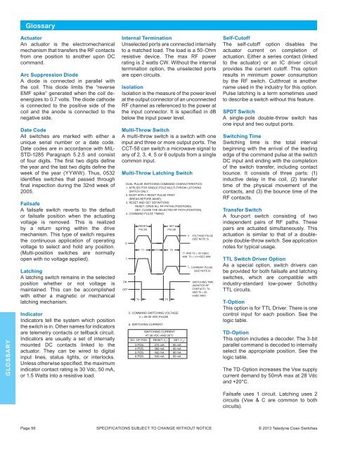
Multi-Throw Latching Switch<br />
DUAL PULSE SWITCHING COMMAND CHARACTERISTICS:<br />
1. APPLIES FOR SINGLE-POLE MULTI-THROW LATCHING<br />
SWITCH ONLY.<br />
2. MUST APPLY RESET PULSE FIRST<br />
(BREAK-BEFORE-MAKE).<br />
3. RESET AND SET DEFINITIONS<br />
RESET: OPEN ALL RF PATHS (POSITIONS).<br />
SET: CLOSE THE SELECTED RF PATH (POSITION).<br />
4. COMMAND PULSE TIMING:<br />
O<br />
RESET<br />
PULSE<br />
T1<br />
T3<br />
I 1<br />
ON<br />
OFF<br />
T4<br />
T5<br />
SET<br />
PULSE<br />
T2<br />
5. COMMAND SWITCHING VOLTAGE:<br />
V = 26-32 VDC PULSE<br />
6. SWITCHING CURRENT:<br />
SWITCHING CURRENT<br />
AT 28 VDC AND 20°C<br />
NO. OF POS. RESET (I 1<br />
) SET (1 2<br />
)<br />
3 POS. 270 mA 90 mA<br />
4 POS. 360 mA 90 mA<br />
5 POS. 450 mA 90 mA<br />
6 POS. 540 mA 90 mA<br />
V<br />
I 2<br />
VOLTAGE PULSE<br />
(SEE NOTE 5)<br />
T1 AND T2 = 30 mSEC<br />
MIN. T3 = 10 mSEC MIN.<br />
CURRENT PULSE<br />
(SEE NOTE 6)<br />
SWITCHING TIME<br />
(MONITOR RF<br />
CONTACT): T4<br />
AND T5 = 20<br />
mSEC MAX<br />
Self-Cutoff<br />
The self-cutoff option disables the<br />
actuator current on completion of<br />
actuation. Either a series contact (linked<br />
to the actuator) or an IC driver circuit<br />
provides the current cutoff. This option<br />
results in minimum power consumption<br />
by the RF switch. Cutthroat is another<br />
name used in the industry for this option.<br />
Pulse latching is a term sometimes used<br />
to describe a switch without this feature.<br />
SPDT Switch<br />
A single-pole double-throw switch has<br />
one input and two output ports.<br />
Switching Time<br />
Switching time is the total interval<br />
beginning with the arrival of the leading<br />
edge of the command pulse at the switch<br />
DC input and ending with the completion<br />
of the switch transfer, including contact<br />
bounce. It consists of three parts: (1)<br />
inductive delay in the coil, (2) transfer<br />
time of the physical movement of the<br />
contacts, and (3) the bounce time of the<br />
RF contacts.<br />
Transfer Switch<br />
A f<strong>our</strong>-port switch consisting of two<br />
independent pairs of RF paths. These<br />
pairs are actuated simultaneously. This<br />
actuation is similar to that of a doublepole<br />
double-throw switch. See application<br />
notes for typical usage.<br />
TTL Switch Driver Option<br />
As a special option, switch drivers can<br />
be provided for both failsafe and latching<br />
switches, which are compatible with<br />
industry-standard low-power Schottky<br />
TTL circuits.<br />
T-Option<br />
This option is for TTL Driver. There is one<br />
control input for each position. See the<br />
logic table.<br />
TD-Option<br />
This option includes a decoder. The 3-bit<br />
parallel command is decoded to internally<br />
select the appropriate position. See the<br />
logic table.<br />
The TD-Option increases the Vsw supply<br />
current demand by 50mA max at 28 Vdc<br />
and +20°C.<br />
Failsafe uses 1 circuit. Latching uses 2<br />
circuits (Vsw & C are common to both<br />
circuits).<br />
Page 56 SPECIFICATIONS SUBJECT TO CHANGE WITHOUT NOTICE © 2013 <strong>Teledyne</strong> Coax <strong>Switches</strong>