Download our Microwave Switches Selection ... - Teledyne Relays
Download our Microwave Switches Selection ... - Teledyne Relays
Download our Microwave Switches Selection ... - Teledyne Relays

You also want an ePaper? Increase the reach of your titles
YUMPU automatically turns print PDFs into web optimized ePapers that Google loves.
Glossary<br />
Performance Parameters<br />
vs Frequency<br />
Generally speaking, the RF performance<br />
of coaxial switches is frequency<br />
dependent. With increasing frequency,<br />
VSWR and insertion loss increase while<br />
isolation decreases. All data sheets<br />
specify these three parameters as “worst<br />
case” at the highest operating frequency.<br />
If the switch is to be used over a narrow<br />
frequency band, better performance can<br />
be achieved.<br />
Actuator Current vs Temperature<br />
The resistance of the actuator coil varies<br />
as a function of temperature. There is<br />
an inverse relationship between the<br />
operating temperature of the switch and<br />
the actuator drive current. For switches<br />
operating at 28 VDC, the approximate<br />
actuator drive current at temperature, T,<br />
can be calculated using the equation:<br />
I T<br />
=<br />
Where:<br />
I A<br />
[1 + .00385 (T-20)]<br />
I T<br />
= Actuator current at temperature, T<br />
I A<br />
= Room temperature actuator current –<br />
see data sheet<br />
T = Temperature of interest in °C<br />
Magnetic Sensitivity<br />
An electro-mechanical switch can be<br />
sensitive to ferrous materials and external<br />
magnetic fi elds. Neighboring ferrous<br />
materials should be permitted no closer<br />
than 0.5 inches and adjacent external<br />
magnetic fi elds should be limited to a fl ux<br />
density of less than 5 Gauss.<br />
Special Feature<br />
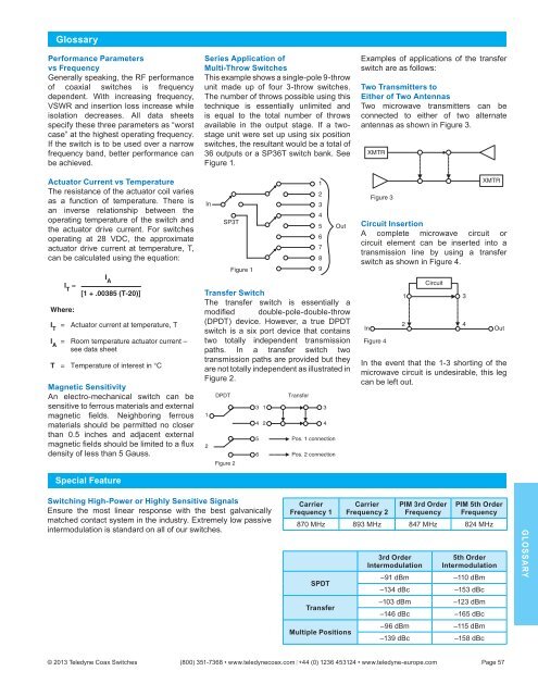
Series Application of<br />
Multi-Throw <strong>Switches</strong><br />
This example shows a single-pole 9-throw<br />
unit made up of f<strong>our</strong> 3-throw switches.<br />
The number of throws possible using this<br />
technique is essentially unlimited and<br />
is equal to the total number of throws<br />
available in the output stage. If a twostage<br />
unit were set up using six position<br />
switches, the resultant would be a total of<br />
36 outputs or a SP36T switch bank. See<br />
Figure 1.<br />
In<br />
SP3T<br />
Figure 1<br />
1<br />
2<br />
3<br />
4<br />
5<br />
6<br />
7<br />
8<br />
9<br />
Out<br />
Transfer Switch<br />
The transfer switch is essentially a<br />
modifi ed double-pole-double-throw<br />
(DPDT) device. However, a true DPDT<br />
switch is a six port device that contains<br />
two totally independent transmission<br />
paths. In a transfer switch two<br />
transmission paths are provided but they<br />
are not totally independent as illustrated in<br />
Figure 2.<br />
1<br />
2<br />
DPDT<br />
Figure 2<br />
3<br />
4<br />
5<br />
6<br />
1<br />
2<br />
Transfer<br />
3<br />
4<br />
Pos. 1 connection<br />
Pos. 2 connection<br />
Examples of applications of the transfer<br />
switch are as follows:<br />
Two Transmitters to<br />
Either of Two Antennas<br />
Two microwave transmitters can be<br />
connected to either of two alternate<br />
antennas as shown in Figure 3.<br />
XMTR<br />
Figure 3<br />
XMTR<br />
Circuit Insertion<br />
A complete microwave circuit or<br />
circuit element can be inserted into a<br />
transmission line by using a transfer<br />
switch as shown in Figure 4.<br />
In<br />
Figure 4<br />
1<br />
Circuit<br />
3<br />
2 4<br />
Out<br />
In the event that the 1-3 shorting of the<br />
microwave circuit is undesirable, this leg<br />
can be left out.<br />
Switching High-Power or Highly Sensitive Signals<br />
Ensure the most linear response with the best galvanically<br />
matched contact system in the industry. Extremely low passive<br />
intermodulation is standard on all of <strong>our</strong> switches.<br />
Carrier<br />
Frequency 1<br />
Carrier<br />
Frequency 2<br />
PIM 3rd Order<br />
Frequency<br />
PIM 5th Order<br />
Frequency<br />
870 MHz 893 MHz 847 MHz 824 MHz<br />
SPDT<br />
Transfer<br />
Multiple Positions<br />
3rd Order<br />
Intermodulation<br />
5th Order<br />
Intermodulation<br />
–91 dBm –110 dBm<br />
–134 dBc –153 dBc<br />
–103 dBm –123 dBm<br />
–146 dBc –165 dBc<br />
–96 dBm –115 dBm<br />
–139 dBc –158 dBc<br />
GLOSSARY<br />
© 2013 <strong>Teledyne</strong> Coax <strong>Switches</strong> (800) 351-7368 • www.teledynecoax.com +44 (0) 1236 453124 • www.teledyne-europe.com Page 57