You also want an ePaper? Increase the reach of your titles
YUMPU automatically turns print PDFs into web optimized ePapers that Google loves.
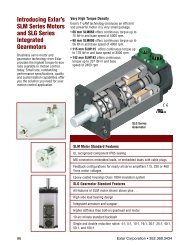
GSM Series Linear Actuators<br />
Rod Eye Dimensions<br />
E<br />
A<br />
A<br />
B<br />
in (mm) GSM20 RE038 GSM30 RE050 GSM40 RE075<br />
ØA 0.50 (12.7) 0.50 (12.7) 0.75 (19.1)<br />
A<br />
øA<br />
B 0.560 (14.2) 0.75 (19.1) 1.25 (31.8)<br />
C 1.00 (25.4) 1.50 (38.1) 2.06 (52.3)<br />
D<br />
C<br />
D 0.50 (12.7) 0.75 (19.1) 1.13 (28.7)<br />
E 0.25 x 45˚ 0.63 (16.0) 0.88 (22.3)<br />
F 3/8 - 24 7/16 - 20 3/4 - 16<br />
GSM Series<br />
F<br />
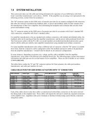
Rod Clevis Pin Dimensions<br />
in (mm) A B C ØD ØE<br />
øD<br />
C<br />
B<br />
C<br />
øE<br />
CP050 1 2.28<br />
(57.9)<br />
CP075 2 3.09<br />
(78.5)<br />
1.94<br />
(49.28)<br />
2.72<br />
(69.1)<br />
0.17<br />
(4.32)<br />
0.19<br />
(4.82)<br />
0.50" +0.000/-0.002<br />
(12.7 mm +0.00/-0.05)<br />
0.75" +0.000/-0.002<br />
(19.1 mm +0.00/-0.05)<br />
0.106<br />
(2.69)<br />
0.14<br />
(3.56)<br />
A<br />
1<br />
Fits GSM30 rear clevis, RC050 and RE050<br />
2<br />
Fits GSM30, 40 and RC075, RE075 and SRM075<br />
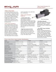
GSM20, GSM30 and GSM40 External<br />
Limit Switch Extension Options<br />
* Dimensions for Anti rotate option<br />
can be seen on page 22.<br />
Dim A<br />
3" (76 mm)<br />
stroke in (mm)<br />
6" (152 mm)<br />
stroke in (mm)<br />
8" (203 mm)<br />
stroke in (mm)<br />
10" (254 mm)<br />
stroke in (mm)<br />
12" (305 mm)<br />
stroke in (mm)<br />
18" (457 mm)<br />
stroke in (mm)<br />
GSM20 5.515 (140.1) 8.515 (216.3) NA 12.5 (317.5) 14.515 (368.7) NA<br />
GSM30 6.932 (176.1) 9.832 (249.7) NA 13.832 (351.3) 15.832 (402.1) 21.832 (554.5)<br />
GSM40 NA 9.832 (249.7) 11.83 (300.5) 13.832 (351.3) 15.832 (402.1) 21.832 (554.5)<br />
36" Flying Leads<br />
L1 L2 L3<br />
DIM "A"<br />
The external limit switch option (requires anti-rotate<br />
option) for the GSM Series of linear actuators provides<br />
the user with 1, 2 or 3 externally mounted adjustable<br />
switches for use as the end of travel limit switches or<br />
home position sensors.<br />
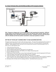
The number of switches desired is selected by ordering<br />
the L1, L2 or L3 option, in which 1, 2 or 3 switches will<br />
be provided, respectively.<br />
The switches are 9-30 VDC powered, PNP output, with<br />
either normally open or normally closed logic operation<br />
depending on the switch configuration ordered. Below<br />
is a diagram which logic operation will be provided for<br />
each switch, based on the option ordered.<br />
Option SW1 SW2 SW3 Switch Type <strong>Exlar</strong> Part Number Turck Part Number<br />
L1 Not Supplied Normally Open Not Supplied Normally Closed Switch 43404 BIM-UNT-RP6X<br />
L2 Normally Closed Not Supplied Normally Closed Normally Open Switch 43403 BIM-UNT-AP6X<br />
L3 Normally Closed Normally Open Normally Closed<br />
Drawings subject to change. Consult <strong>Exlar</strong> for certified drawings.<br />
9.52.500.6200 | www.exlar.com 53