UNVENTED (VENT-FREE) GAS STOVE HEATER - Desa
UNVENTED (VENT-FREE) GAS STOVE HEATER - Desa
UNVENTED (VENT-FREE) GAS STOVE HEATER - Desa

You also want an ePaper? Increase the reach of your titles
YUMPU automatically turns print PDFs into web optimized ePapers that Google loves.
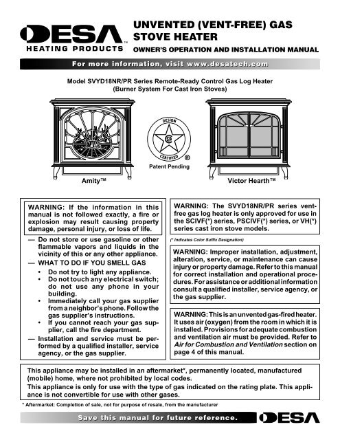
<strong>UN<strong>VENT</strong>ED</strong> (<strong>VENT</strong>-<strong>FREE</strong>) <strong>GAS</strong><br />
<strong>STOVE</strong> <strong>HEATER</strong><br />
OWNER’S OPERATION AND INSTALLATION MANUAL<br />
For more information, visit www.desatech.com<br />
Model SVYD18NR/PR Series Remote-Ready Control Gas Log Heater<br />
(Burner System For Cast Iron Stoves)<br />
Patent Pending<br />
Amity<br />
Victor Hearth<br />
WARNING: If the information in this<br />
manual is not followed exactly, a fire or<br />
explosion may result causing property<br />
damage, personal injury, or loss of life.<br />
— Do not store or use gasoline or other<br />
flammable vapors and liquids in the<br />
vicinity of this or any other appliance.<br />
— WHAT TO DO IF YOU SMELL <strong>GAS</strong><br />
• Do not try to light any appliance.<br />
• Do not touch any electrical switch;<br />
do not use any phone in your<br />
building.<br />
• Immediately call your gas supplier<br />
from a neighbor’s phone. Follow the<br />
gas supplier’s instructions.<br />
• If you cannot reach your gas supplier,<br />
call the fire department.<br />
— Installation and service must be performed<br />
by a qualified installer, service<br />
agency, or the gas supplier.<br />
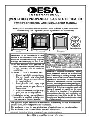
WARNING: The SVYD18NR/PR series ventfree<br />
gas log heater is only approved for use in<br />
the SCIVF(*) series, PSCIVF(*) series, or VH(*)<br />
series cast iron stove models.<br />
(* Indicates Color Suffix Designation)<br />
WARNING: Improper installation, adjustment,<br />
alteration, service, or maintenance can cause<br />
injury or property damage. Refer to this manual<br />
for correct installation and operational procedures.<br />
For assistance or additional information<br />
consult a qualified installer, service agency, or<br />
the gas supplier.<br />
WARNING: This is an unvented gas-fired heater.<br />
It uses air (oxygen) from the room in which it is<br />
installed. Provisions for adequate combustion<br />
and ventilation air must be provided. Refer to<br />
Air for Combustion and Ventilation section on<br />
page 4 of this manual.<br />
This appliance may be installed in an aftermarket*, permanently located, manufactured<br />
(mobile) home, where not prohibited by local codes.<br />
This appliance is only for use with the type of gas indicated on the rating plate. This appliance<br />
is not convertible for use with other gases.<br />
* Aftermarket: Completion of sale, not for purpose of resale, from the manufacturer<br />
Save this manual for future reference.
2<br />
TABLE OF CONTENTS<br />
SAFETY INFORMATION<br />
TABLE OF CONTENTS<br />
SAFETY INFORMATION ............................................................ 2<br />
PRODUCT IDENTIFICATION ..................................................... 3<br />
LOCAL CODES ........................................................................... 3<br />
PRODUCT FEATURES .............................................................. 4<br />
AIR FOR COMBUSTION AND <strong>VENT</strong>ILATION ........................... 4<br />
INSTALLATION ........................................................................... 6<br />
OPERATING <strong>HEATER</strong> .............................................................. 13<br />
INSPECTING BURNERS.......................................................... 16<br />
CLEANING AND MAINTENANCE ............................................ 16<br />
TROUBLESHOOTING .............................................................. 18<br />
SPECIFICATIONS .................................................................... 21<br />
WIRING DIAGRAM ................................................................... 21<br />
REPLACEMENT PARTS .......................................................... 21<br />
SERVICE HINTS....................................................................... 21<br />
TECHNICAL SERVICE ............................................................. 21<br />
ILLUSTRATED PARTS BREAKDOWN AND PARTS LIST ....... 22<br />
ACCESSORIES ........................................................................ 26<br />
OWNER’S REGISTRATION FORM .......................................... 27<br />
WARRANTY INFORMATION ...................................... Back Cover<br />
SAFETY INFORMATION<br />
WARNINGS<br />
WARNING: This product contains and/or generates<br />
chemicals known to the State of California to cause<br />
cancer or birth defects, or other reproductive harm.<br />
IMPORTANT: Read this owner’s manual carefully and<br />
completely before trying to assemble, operate, or service<br />
this heater. Improper use of this heater can cause<br />
serious injury or death from burns, fire, explosion,<br />
electrical shock, and carbon monoxide poisoning.<br />
DANGER: Carbon monoxide poisoning may lead<br />
to death!<br />
Carbon Monoxide Poisoning: Early signs of carbon monoxide<br />
poisoning resemble the flu, with headaches, dizziness, or nausea.<br />
If you have these signs, the heater may not be working properly.<br />
Get fresh air at once! Have heater serviced. Some people are<br />
more affected by carbon monoxide than others. These include<br />
pregnant women, people with heart or lung disease or anemia,<br />
those under the influence of alcohol, and those at high altitudes.<br />
Natural and Propane/LP Gas: Natural and propane/LP gases are<br />
odorless. An odor-making agent is added to the gas. The odor<br />
helps you detect a gas leak. However, the odor added to the gas can<br />
fade. Gas may be present even though no odor exists.<br />
Make certain you read and understand all warnings. Keep this manual<br />
for reference. It is your guide to safe and proper operation of this heater.<br />
WARNING: Any change to this heater or its controls<br />
can be dangerous.<br />
WARNING: Do not allow fans to blow directly into<br />
the fireplace. Avoid any drafts that alter burner flame<br />
patterns. Ceiling fans can create drafts that alter<br />
burner flame patterns. Altered burner patterns can<br />
cause sooting.<br />
WARNING: Do not use a blower insert, heat<br />
exchanger insert, or other accessory not approved<br />
for use with this fireplace.<br />
Due to high temperatures, the appliance should be<br />
located out of traffic and away from furniture and<br />
draperies.<br />
Do not place clothing or other flammable material<br />
on or near the appliance. Never place any objects<br />
on the heater.<br />
Stove becomes very hot when running heater. Keep<br />
children and adults away from hot surface to avoid burns<br />
or clothing ignition. Heater will remain hot for a time after<br />
shutdown. Allow surface to cool before touching.<br />
Carefully supervise young children when they are in<br />
the room with stove. When using the optional handheld<br />
remote accessory, keep selector switch in the<br />
OFF position to prevent children from turning on<br />
burners with remote.<br />
Keep the appliance area clear and free from combustible<br />
materials, gasoline, and other flammable vapors<br />
and liquids.<br />
For more information, visit www.desatech.com<br />
111162-01B
ON<br />
OFF<br />
REMOTE<br />
LO<br />
HI<br />
ON<br />
PILOT<br />
SAFETY INFORMATION<br />
PRODUCT IDENTIFICATION<br />
LOCAL CODES<br />
3<br />
SAFETY INFORMATION<br />
Continued<br />
1. This appliance is only for use with the type of gas indicated on<br />
the rating plate. This appliance is not convertible for use with<br />
other gases.<br />
2. Do not place propane/LP supply tank(s) inside any structure. Locate<br />
propane/LP supply tank(s) outdoors (propane/LP units only).<br />
3. If you smell gas<br />
• shut off gas supply<br />
• do not try to light any appliance<br />
• do not touch any electrical switch; do not use any phone in<br />
your building<br />
• immediately call your gas supplier from a neighbor’s phone.<br />
Follow the gas supplier’s instructions<br />
• if you cannot reach your gas supplier, call the fire department<br />
4. This heater shall not be installed in a bedroom or bathroom.<br />
5. Do not use this stove as a wood burning fireplace. Use only model<br />
SVYD18PR/NR series vent-free gas log heater for SCIVF(*),<br />
PSCIVF(*), and VH(*) series cast iron stove models.<br />
6. Do not add extra logs or ornaments such as pine cones, vermiculite,<br />
or rock wool. Using these added items can cause sooting.<br />
7. This log heater is designed to be smokeless. If logs ever appear<br />
to smoke, turn off heater and call a qualified service person.<br />
Note: During initial operation, slight smoking could occur due<br />
to log curing and heater burning manufacturing residues.<br />
8. To prevent the creation of soot, follow the instructions in Cleaning<br />
and Maintenance, page 16.<br />
9. Before using furniture polish, wax, carpet cleaners, or similar<br />
products, turn heater off. If heated, the vapors from these products<br />
may create a white powder residue within burner box or<br />
on adjacent walls or furniture.<br />
10. This heater needs fresh, outside air ventilation to run properly.<br />
This heater has an Oxygen Depletion Sensing (ODS) safety<br />
shutoff system. The ODS shuts down the heater if not enough<br />
fresh air is available. See Air for Combustion and Ventilation,<br />
pages 4 through 6. If heater keeps shutting off, see Troubleshooting,<br />
pages 18 through 20.<br />
11. Do not run heater<br />
• where flammable liquids or vapors are used or stored<br />
• under dusty conditions<br />
12. Do not use this stove to cook food or burn paper or other objects.<br />
13. Do not use heater if any part has been exposed to or under<br />
water. Immediately call a qualified service technician to inspect<br />
the room heater and to replace any part of the control<br />
system and any gas control which has been under water.<br />
14. Do not operate heater if any log is broken. Do not operate<br />
heater if a log is chipped (dime-sized or larger).<br />
15. Turn heater off and let cool before servicing. Only a qualified<br />
service person should service and repair heater.<br />
16. Operating heater above elevations of 4,500 feet could cause<br />
pilot outage.<br />
17. To prevent performance problems, the use of a propane/LP<br />
tank of less than 100 lb. capacity (propane/LP units only).<br />
18. Provide adequate clearances around air openings.<br />
PRODUCT IDENTIFICATION<br />
Stove<br />
Body<br />
One Piece<br />
Log Set<br />
Inside Stove<br />
Cavity<br />
Stove Door<br />
(Shown in the<br />
open position)<br />
Remote<br />
Piezo Ignitor Selector<br />
Switch<br />
Gas Log Heater<br />
Base Assembly<br />
Figure 1 - Typical Stove Cabinet Model with Gas Log Heater<br />
(Shown is Amity Model with Model SVYD18PR/NR Heater)<br />
LOCAL CODES<br />
OFF<br />
Control<br />
Knob<br />
Flame Adjustment<br />
Knob<br />
Install and use heater with care. Follow all local codes. In the<br />
absence of local codes, use the latest edition of The National Fuel<br />
Gas Code ANSI Z223.1/NFPA 54*.<br />
*Available from:<br />
American National Standards Institute, Inc.<br />
1430 Broadway<br />
New York, NY 10018<br />
National Fire Protection Association, Inc.<br />
Batterymarch Park<br />
Quincy, MA 02269<br />
111162-01B<br />
For more information, visit www.desatech.com
4<br />
PRODUCT FEATURES<br />
AIR FOR COMBUSTION AND <strong>VENT</strong>ILATION<br />
Providing Adequate Ventilation<br />
PRODUCT FEATURES<br />
OPERATION<br />
This heater is clean burning. It requires no outside venting. There is<br />
no heat loss out a vent or up a chimney. Heat is generated by realistic,<br />
dancing yellow flames. This heater is designed for vent-free operation.<br />
State and local codes in some areas prohibit the use of vent-free<br />
heaters.<br />
SAFETY PILOT<br />
This heater has a pilot with an Oxygen Depletion Sensing (ODS)<br />
safety shutoff system. The ODS/pilot is a required feature for ventfree<br />
room heaters. The ODS/pilot shuts off the heater if there is not<br />
enough fresh air.<br />
PIEZO IGNITION SYSTEM<br />
This heater has a piezo ignitor. This system requires no matches,<br />
batteries, or other sources to light heater.<br />
AIR FOR COMBUSTION AND<br />
<strong>VENT</strong>ILATION<br />
WARNING: This heater shall not be installed in<br />
a confined space or unusually tight construction<br />
unless provisions are provided for adequate combustion<br />
and ventilation air. Read the following instructions<br />
to insure proper fresh air for this and<br />
other fuel-burning appliances in your home.<br />
Today’s homes are built more energy efficient than ever. New<br />
materials, increased insulation, and new construction methods help<br />
reduce heat loss in homes. Home owners weather strip and caulk<br />
around windows and doors to keep the cold air out and the warm air<br />
in. During heating months, home owners want their homes as<br />
airtight as possible.<br />
While it is good to make your home energy efficient, your home<br />
needs to breathe. Fresh air must enter your home. All fuel-burning<br />
appliances need fresh air for proper combustion and ventilation.<br />
Exhaust fans, fireplaces, clothes dryers, and fuel burning appliances<br />
draw air from the house to operate. You must provide adequate fresh<br />
air for these appliances. This will insure proper venting of vented<br />
fuel-burning appliances.<br />
PROVIDING ADEQUATE <strong>VENT</strong>ILATION<br />
The following are excerpts from National Fuel Gas Code,<br />
ANSI Z223.1/ NFPA 54, Section 5.3, Air for Combustion and<br />
Ventilation.<br />
All spaces in homes fall into one of the three following ventilation<br />
classifications:<br />
1. Unusually Tight Construction<br />
2. Unconfined Space<br />
3. Confined Space<br />
The information on pages 4 through 6 will help you classify your<br />
space and provide adequate ventilation.<br />
Unusually Tight Construction<br />
The air that leaks around doors and windows may provide enough<br />
fresh air for combustion and ventilation. However, in buildings of<br />
unusually tight construction, you must provide additional fresh air.<br />
Unusually tight construction is defined as construction<br />
where:<br />
a. walls and ceilings exposed to the outside atmosphere<br />
have a continuous water vapor retarder with a rating<br />
of one perm (6 x 10 -11 kg per pa-sec-m 2 ) or less with<br />
openings gasketed or sealed and<br />
b. weather stripping has been added on openable windows<br />
and doors and<br />
c. caulking or sealants are applied to areas such as<br />
joints around window and door frames, between sole<br />
plates and floors, between wall-ceiling joints, between<br />
wall panels, at penetrations for plumbing, electrical,<br />
and gas lines, and at other openings.<br />
If your home meets all of the three criteria above, you<br />
must provide additional fresh air. See Ventilation Air<br />
From Outdoors, page 6.<br />
If your home does not meet all of the three criteria above,<br />
proceed to Determining Fresh-Air Flow For Heater Location,<br />
page 5.<br />
Confined and Unconfined Space<br />
The National Fuel Gas Code, ANSI Z223.1/NFPA 54 defines a<br />
confined space as a space whose volume is less than 50 cubic feet<br />
per 1,000 Btu per hour (4.8 m 3 per kw) of the aggregate input rating<br />
of all appliances installed in that space and an unconfined space as<br />
a space whose volume is not less than 50 cubic feet per 1,000 Btu per<br />
hour (4.8 m 3 per kw) of the aggregate input rating of all appliances<br />
installed in that space. Rooms communicating directly with the<br />
space in which the appliances are installed*, through openings not<br />
furnished with doors, are considered a part of the unconfined space.<br />
* Adjoining rooms are communicating only if there are doorless<br />
passageways or ventilation grills between them.<br />
For more information, visit www.desatech.com<br />
111162-01B
AIR FOR COMBUSTION AND <strong>VENT</strong>ILATION<br />
Determining fresh-air flow for heater location<br />
5<br />
AIR FOR COMBUSTION AND<br />
<strong>VENT</strong>ILATION<br />
Continued<br />
DETERMINING FRESH-AIR FLOW FOR<br />
<strong>HEATER</strong> LOCATION<br />
Determining if You Have a Confined or<br />
Unconfined Space<br />
Use this work sheet to determine if you have a confined or unconfined space.<br />
Space: Includes the room in which you will install heater plus any adjoining<br />
rooms with doorless passageways or ventilation grills between the rooms.<br />
1. Determine the volume of the space (length x width x height).<br />
Length x Width x Height = ___________ cu. ft. (volume of space)<br />
Example: Space size 20 ft. (length) x 16 ft. (width) x 8 ft. (ceiling<br />
height) = 2560 cu. ft. (volume of space)<br />
If additional ventilation to adjoining room is supplied with grills or openings,<br />
add the volume of these rooms to the total volume of the space.<br />
2. Multiply the space volume by 20 to determine the maximum Btu/Hr<br />
the space can support.<br />
__________ (volume of space) x 20 = (Maximum Btu/Hr the space<br />
can support)<br />
Example: 2560 cu. ft. (volume of space) x 20 = 51,200 (maximum<br />
Btu/Hr the space can support)<br />
3. Add the Btu/Hr of all fuel burning appliances in the space.<br />
Vent-free heater _____________ Btu/Hr<br />
Gas water heater* _____________ Btu/Hr<br />
Gas furnace<br />
_____________ Btu/Hr<br />
Vented gas heater _____________ Btu/Hr<br />
Gas fireplace logs _____________ Btu/Hr<br />
Other gas appliances* + _____________ Btu/Hr<br />
Total<br />
= _____________ Btu/Hr<br />
* Do not include direct-vent gas appliances. Direct-vent draws combustion<br />
air from the outdoors and vents to the outdoors.<br />
Example:<br />
Gas water heater _____________ 40,000 Btu/Hr<br />
Vent-free heater + _____________ 30,000 Btu/Hr<br />
Total<br />
= _____________ 70,000 Btu/Hr<br />
4. Compare the maximum Btu/Hr the space can support with the actual<br />
amount of Btu/Hr used.<br />
__________________ Btu/Hr (maximum the space can support)<br />
__________________ Btu/Hr (actual amount of Btu/Hr used)<br />
Example: 51,200 Btu/Hr (maximum the space can support)<br />
70,000 Btu/Hr (actual amount of Btu/Hr used)<br />
The space in the above example is a confined space because the actual Btu/<br />
Hr used is more than the maximum Btu/Hr the space can support. You must<br />
provide additional fresh air. Your options are as follows:<br />
A. Rework worksheet, adding the space of an adjoining room. If the<br />
extra space provides an unconfined space, remove door to adjoining<br />
room or add ventilation grills between rooms. See Ventilation Air From<br />
Inside Building, page 6.<br />
B. Vent room directly to the outdoors. See Ventilation Air From Outdoors,<br />
page 6.<br />
C. Install a lower Btu/Hr heater, if lower Btu/Hr size makes room<br />
unconfined.<br />
If the actual Btu/Hr used is less than the maximum Btu/Hr the space can<br />
support, the space is an unconfined space. You will need no additional fresh<br />
air ventilation.<br />
WARNING: If the area in which the heater may be<br />
operated is smaller than that defined as an unconfined<br />
space or if the building is of unusually tight<br />
construction, provide adequate combustion and ventilation<br />
air by one of the methods described in the<br />
National Fuel Gas Code, ANSI Z223.1/NFPA 54 Section<br />
5.3 or applicable local codes.<br />
111162-01B<br />
For more information, visit www.desatech.com
6<br />
AIR FOR COMBUSTION AND <strong>VENT</strong>ILATION<br />
Ventilation Air<br />
INSTALLATION<br />
AIR FOR COMBUSTION AND<br />
<strong>VENT</strong>ILATION<br />
Continued<br />
<strong>VENT</strong>ILATION AIR<br />
Ventilation Air From Inside Building<br />
This fresh air would come from an adjoining unconfined space.<br />
When ventilating to an adjoining unconfined space, you must<br />
provide two permanent openings: one within 12" of the ceiling and<br />
one within 12" of the floor on the wall connecting the two spaces<br />
(see options 1 and 2, Figure 2). You can also remove door into<br />
adjoining room (see option 3, Figure 2). Follow the National Fuel<br />
Gas Code, ANSI Z223.1/NFPA 54, Section 5.3, Air for Combustion<br />
and Ventilation for required size of ventilation grills or ducts.<br />
Ventilation Air From Outdoors<br />
Provide extra fresh air by using ventilation grills or ducts. You must<br />
provide two permanent openings: one within 12" of the ceiling and<br />
one within 12" of the floor. Connect these items directly to the<br />
outdoors or spaces open to the outdoors. These spaces include attics<br />
and crawl spaces. Follow the National Fuel Gas Code, ANSI<br />
Z223.1/NFPA 5, Section 5.3, Air for Combustion and Ventilation<br />
for required size of ventilation grills or ducts.<br />
IMPORTANT: Do not provide openings for inlet or outlet air into<br />
attic if attic has a thermostat-controlled power vent. Heated air<br />
entering the attic will activate the power vent.<br />
Ventilation<br />
Grills<br />
Into Adjoining<br />
Room,<br />
Option 1<br />
Or<br />
Remove<br />
Door into<br />
Adjoining<br />
Room,<br />
Option<br />
3<br />
12"<br />
Figure 2 - Ventilation Air from Inside Building (Amity Stove<br />
Model Shown)<br />
12"<br />
Ventilation Grills<br />
Into Adjoining Room,<br />
Option 2<br />
Outlet<br />
Air<br />
Inlet<br />
Air<br />
Outlet<br />
Air<br />
Inlet Air<br />
Ventilated<br />
Attic<br />
Ventilated<br />
Crawl Space<br />
To Attic<br />
To<br />
Crawl<br />
Space<br />
Figure 3 - Ventilation Air from Outdoors (Amity Stove Model<br />
Shown)<br />
INSTALLATION<br />
NOTICE: This heater is intended for use as supplemental<br />
heat. Use this heater along with your primary<br />
heating system. Do not install this heater as your<br />
primary heat source. If you have a central heating<br />
system, you may run system’s circulating blower<br />
while using heater. This will help circulate the heat<br />
throughout the house. In the event of a power outage,<br />
you can use this heater as your primary heat source.<br />
WARNING: A qualified service person must install<br />
heater. Follow all local codes.<br />
WARNING: Never install the heater<br />
• in a bedroom or bathroom<br />
• in a recreational vehicle<br />
• where curtains, furniture, clothing, or other flammable<br />
objects are less than 42 inches from the<br />
front, top, or sides of the heater<br />
• in high traffic areas<br />
• in windy or drafty areas<br />
For more information, visit www.desatech.com<br />
111162-01B
INSTALLATION<br />
Check Gas Type<br />
Clearances to Combustibles<br />
7<br />
INSTALLATION<br />
Continued<br />
CAUTION: This heater creates warm air currents.<br />
These currents move heat to wall surfaces next to<br />
heater. Installing heater next to vinyl or cloth wall<br />
coverings or operating heater where impurities (such<br />
as, but not limited to, tobacco smoke, aromatic<br />
candles, cleaning fluids, oil or kerosene lamps, etc.)<br />
in the air exist, may discolor walls or cause odors.<br />
Ceiling<br />
48"<br />
Minimum<br />
Front View<br />
IMPORTANT: Vent-free heaters add moisture to the air. Although<br />
this is beneficial, installing heater in rooms without enough ventilation<br />
air may cause mildew to form from too much moisture. See<br />
Air for Combustion and Ventilation, pages 4 through 6.<br />
Side Wall<br />
12"<br />
Minimum<br />
12"<br />
Minimum<br />
Side Wall<br />
CHECK <strong>GAS</strong> TYPE<br />
Use the correct gas type (natural or propane/LP) for your unit. If<br />
your gas supply is not correct, do not install heater. Call dealer where<br />
you bought fireplace for proper type fireplace.<br />
CLEARANCES TO COMBUSTIBLES<br />
(Vent-Free Operation Only)<br />
WARNING: Maintain the minimum clearances. If<br />
you can, provide greater clearances from floor, ceiling,<br />
and adjoining side and back walls.<br />
Carefully follow the instructions below. This stove is a freestanding<br />
unit designed to set directly on the floor. IMPORTANT: You must<br />
maintain minimum wall and ceiling clearances during installation.<br />
The minimum clearances are shown in Figure 4. Measure from<br />
outermost point of stove top.<br />
Minimum Wall and Ceiling Clearances (see Figure 4)<br />
A. Clearances from outermost point of stove top to any combustible<br />
side wall should not be less than 12 inches.<br />
B. Clearances from outermost point of stove top to any combustible<br />
back wall should not be less than 6 inches (includes corner<br />
installations).<br />
C. Clearances from the stove top to the ceiling should not be less<br />
than 48 inches.<br />
Side Wall<br />
Corner<br />
Wall<br />
6 "<br />
Minimum<br />
12 "<br />
Minimum<br />
Back Wall<br />
Top View<br />
Wall<br />
6 "<br />
Minimum<br />
Front of<br />
Stove Unit<br />
Side View<br />
6 "<br />
Minimum<br />
12 "<br />
Minimum<br />
Front of<br />
Stove Unit<br />
Ceiling<br />
48"<br />
Minimum<br />
6"<br />
Minimum<br />
Side Wall<br />
Back Wall<br />
Floor<br />
Figure 4 - Minimum Clearance to Walls and Ceiling (Stove May<br />
Vary Depending on Model)<br />
111162-01B<br />
For more information, visit www.desatech.com
8<br />
INSTALLATION<br />
Stove Cavity Assembly<br />
INSTALLATION<br />
Continued<br />
<strong>STOVE</strong> CAVITY ASSEMBLY<br />
1. Lift off corrugated box enclosing stove body crating.<br />
2. Remove all screws fastening the wood frame enclosure. Spread<br />
wood frame open and lift away from plastic-bagged stove body.<br />
The bottom pieces of pallet wood will remain bolted to the<br />
stove body.<br />
3. Remove plastic bag from stove body.<br />
4. Remove back panel from stove (see Figure 5). Use an adjustable<br />
wrench or a 10 mm socket. Remove six (6) bolts and washers.<br />
Keep bolts and washers to reattach back panel later.<br />
5. Remove all contents from inside stove cavity. Contents include:<br />
(1) - Stove bottom<br />
(4) - Legs (Amity and Victor Hearth models include leg<br />
leveler bolts)<br />
(1) - Bottom door<br />
(1) - Top grate<br />
(1) - Hardware kit bag with fasteners<br />
6. Carefully lay stove body on back to attach bottom components<br />
to stove body (see Figure 6). Rest stove on drop cloth or blanket<br />
to avoid scratching stove edges.<br />
7. Remove remaining pallet wood attached to bottom of stove<br />
body (see Figure 7). Use an adjustable wrench to remove bolts.<br />
Bolt<br />
Product<br />
Identification<br />
Label<br />
Figure 5 - Removing Back Panel<br />
Back Stove<br />
Panel<br />
8. Fasten each leg to stove with four (4) M8 x 1.25 - 20mm bolts.<br />
Use a flat washer and lock washer with each bolt. Tighten bolts<br />
into threaded holes on stove body (see Figures 8 and 9). Use<br />
an adjustable wrench or a 12mm socket.<br />
Bolt<br />
Pallet<br />
Wood<br />
Figure 7 - Removing Pallet Wood From The Bottom of The Stove<br />
Door Hinge Step<br />
Bolt Hole<br />
Leg<br />
Hole<br />
Leg<br />
Hole<br />
Front<br />
Pallet<br />
Wood<br />
Bottom Of<br />
Stove Unit<br />
Figure 8 - Locating Threaded Holes for Stove Bottom, Legs, and<br />
Door Attachment (Appearance May Vary Depending on Model)<br />
Washers<br />
Bottom Of<br />
Stove Unit<br />
Front<br />
Holes for<br />
Stove<br />
Bottom<br />
Door Catch Bolt<br />
With Adjustable<br />
Hex Nuts Hole<br />
Leg Hole<br />
Bottom Of<br />
Stove Unit<br />
Leg Hole<br />
Top of Stove Unit<br />
Front of<br />
Stove<br />
Unit<br />
Drop<br />
Cloth/<br />
Blanket<br />
Pallet<br />
Wood<br />
Bolted to<br />
Stove<br />
Body<br />
Bottom<br />
Front of<br />
Stove Unit<br />
Top of<br />
Stove Unit<br />
Bolt<br />
Leg<br />
Figure 9 - Attaching Stove Legs (Amity Model Shown)<br />
Figure 6 - Laying Down Stove On Side (Stove Style May Vary<br />
Depending on Model)<br />
For more information, visit www.desatech.com<br />
111162-01B
INSTALLATION<br />
Stove Cavity Assembly (Cont.)<br />
9<br />
INSTALLATION<br />
Continued<br />
9. Fasten stove bottom to stove with four (4) M6 x 1 - 25mm<br />
bolts. Use a flat washer and lock washer with each bolt. Tighten<br />
bolts into threaded holes on stove body (see Figure 8, page 8,<br />
and Figure 10). Use an adjustable wrench or a 10mm socket.<br />
10. Attach stove door by inserting step bolt through door hinge pivot<br />
hole and into threaded hole in stove body (see Figure 8, page 8 and<br />
Figure 11). Use an adjustable wrench or a 12mm socket to fasten<br />
step bolt. Tighten step bolt until snug. Make sure door moves freely.<br />
11. Install door catch bolt (M8 x 1.25-55mm with two M8 hex<br />
nuts) into threaded hole on stove body (see Figure 8, page 8).<br />
Use an adjustable wrench or a 12mm socket. The catch bolt<br />
has two hex nuts attached to it (see Figure 12). The top nut is a<br />
bolt stop and the bottom nut is for door leveling adjustment.<br />
12. Check general catch bolt alignment with door claw. Make<br />
final adjustment and door leveling after stove is in normal<br />
standing position.<br />
13. Carefully lift stove back up on its four attached legs.<br />
14. Set top grate into stove top.<br />
15. If available, install gas log heater inside stove cavity before<br />
installing the back panel (see Installing Gas Log Heater Into<br />
Stove, page 10).<br />
16. Fasten back panel to stove with six (6) M6 x 1 - 20mm bolts<br />
and washers. Make sure product identification label is located<br />
on the outside in lower left-hand corner.<br />
Washers<br />
Bolt<br />
Stove<br />
Bottom<br />
Bottom Of<br />
Stove Unit<br />
Figure 10 - Attaching Stove Bottom (Amity Model Shown)<br />
Stove<br />
Door<br />
Door<br />
Hinge<br />
Step Bolt<br />
Stove<br />
Bolt Shoulder Bottom<br />
Figure 11 - Attaching Stove Door (Appearance May Vary<br />
Depending on Model)<br />
Door<br />
Threaded<br />
Hole<br />
Door<br />
Claw<br />
Stove<br />
Door<br />
Door<br />
Hinge<br />
Step<br />
Bolt<br />
Bolt Stop<br />
Adjusting<br />
Nut<br />
Catch<br />
Bolt<br />
Figure 12 - Catch Bolt and Door Claw Orientation<br />
Bolt<br />
Shoulder<br />
CAUTION: Do not remove the data plates attached<br />
to the heater base assembly. The data plates contain<br />
important warranty and safety information.<br />
WARNING: Failure to position the parts in accordance<br />
with these diagrams or failure to use only parts<br />
specifically approved with this heater may result in<br />
property damage or personal injury.<br />
CAUTION: After installation and periodically thereafter,<br />
check to ensure that no flame comes in contact<br />
with any log. With the heater set to HI, check to see if<br />
flames contact any log. If so, reposition logs according<br />
to the log installation instructions in this manual.<br />
Flames contacting logs will create soot.<br />
111162-01B<br />
For more information, visit www.desatech.com
LO<br />
HI<br />
ON<br />
OFF<br />
PILOT<br />
10<br />
INSTALLATION<br />
Installing Gas Log Heater Into Stove<br />
INSTALLATION<br />
Continued<br />
INSTALLING <strong>GAS</strong> LOG <strong>HEATER</strong> INTO <strong>STOVE</strong><br />
1. Remove log and gas log heater from carton. Note: Do not pick<br />
up gas log heater by the burner itself. This could damage heater.<br />
Always handle the gas log heater by the heater base only.<br />
2. Remove all protective packaging applied to log and gas log heater<br />
for shipment.<br />
3. Check all items for any shipping damage. If damaged, promptly<br />
inform dealer where you bought heater.<br />
4. If not already removed, remove back panel from assembled<br />
stove body (see Figure 5, page 8). Use an adjustable wrench or<br />
a 10 mm socket. Remove six (6) bolts and washers. Keep bolts<br />
and washers to reattach back panel later.<br />
5. Set gas log heater inside stove. Make sure control knob extension<br />
passes through bottom front opening (see Figure 13).<br />
6. Align outside holes on heater base with four (4) mounting holes<br />
on the stove bottom (see Figure 13).<br />
7. Fasten heater base to stove bottom with #10-24 x .50 bolts and<br />
hex nuts provided with gas log heater (see Figure 14). Attachment<br />
hardware is factory packed inside plastic bag with installation<br />
manual and owner’s registration card. Push bolt through<br />
heater base mounting hole and through stove bottom. Connect<br />
hex nut to bolt on underside of stove bottom. The bolt hex<br />
head is for a 5/16" socket and the hex nuts are for a 3/8" socket.<br />
If sockets are not available, use adjustable wrenches.<br />
8. Set one-piece log on heater base as shown in Figure 15. Make<br />
sure middle section at bottom of log is seated into "U" shaped<br />
cutout in center of heater base. Log will fit securely on base.<br />
IMPORTANT: Make sure log does not cover any burner ports<br />
and does not touch the stove cavity (see Figure 16).<br />
9. Fasten back panel to stove with six (6) M6 x 1.20mm bolts and<br />
washers. Make sure product identification label is located on the<br />
outside lower left-hand corner.<br />
10. Place freestanding stove in desired position in room. Be sure<br />
to maintain clearances to combustibles as outlined on page 7.<br />
Bottom<br />
Front<br />
Opening<br />
Figure 13 - Placing Heater Base In Stove Cavity (Appearance<br />
May Vary Depending on Model)<br />
Figure 14 - Fastening Heater Base to Stove Drop Bottom<br />
Heater<br />
Base<br />
Bolt<br />
Bolt<br />
Hex Nut<br />
Heater Base<br />
One-Piece<br />
Log Set<br />
Middle Section at<br />
Bottom of Log Set<br />
Burner<br />
Figure 15 - Installing One-Piece Stove Log Set<br />
Burner<br />
Stove<br />
Bottom<br />
Heater<br />
Base<br />
Stove Bottom<br />
"U" Shaped Cutout<br />
in Chassis<br />
Safety Pilot<br />
Location<br />
Burner Porting<br />
Areas (double<br />
slotted rectangular<br />
openings)<br />
One-Piece<br />
Log Set<br />
Figure 16 - Top View of One-Piece Log Set on Gas Log Heater<br />
For more information, visit www.desatech.com<br />
111162-01B
INSTALLATION<br />
Connecting to Gas Supply<br />
11<br />
INSTALLATION<br />
Continued<br />
CONNECTING TO <strong>GAS</strong> SUPPLY<br />
WARNING: This appliance requires a 1/2" NPT<br />
(National Pipe Thread) inlet connection to the pressure<br />
regulator.<br />
Stove<br />
Unit<br />
Front<br />
Side View<br />
Back<br />
Stove<br />
Panel<br />
Product<br />
Identification<br />
Label<br />
Back View<br />
WARNING: A qualified service person must connect<br />
heater to gas supply. Follow all local codes.<br />
CAUTION: Never connect propane/LP heater directly<br />
to the propane/LP supply. This heater requires<br />
an external regulator (not supplied). Install the external<br />
regulator between the heater and propane/LP supply.<br />
WARNING: Never connect natural gas heater to<br />
private (non-utility) gas wells. This gas is commonly<br />
known as wellhead gas.<br />
Installation Items Needed<br />
Before installing heater, make sure you have the items listed below.<br />
• external regulator - propane/LP only (supplied by installer)<br />
• piping (check local codes)<br />
• sealant (resistant to propane/LP gas)<br />
• equipment shutoff valve *<br />
• test gauge connection *<br />
• sediment trap<br />
• tee joint<br />
• pipe wrench<br />
* A CSA design-certified equipment shutoff valve with 1/8" NPT<br />
tap is an acceptable alternative to test gauge connection. Purchase<br />
the optional CSA design-certified equipment shutoff valve from<br />
your dealer. See Accessories, page 26.<br />
The gas inlet connection for the stove heater is located on the lower<br />
right-hand side of the stove when viewed from the front of the unit.<br />
The gas connection can be made either through the bottom right side<br />
or through the lower back opening as illustrated in Figure 17. Make<br />
sure gas log heater is secured to the stove cavity assembly.<br />
For propane/LP units, installer must supply an external regulator.<br />
The external regulator will reduce incoming gas pressure. You must<br />
reduce incoming gas pressure to between 11 and 14 inches of water.<br />
If you do not reduce incoming gas pressure, heater regulator damage<br />
could occur. Install external regulator with the vent pointing down<br />
as shown in Figure 18. Pointing the vent down protects it from<br />
freezing rain or sleet.<br />
Gas Inlet<br />
Connection<br />
Access<br />
Gas Log Heater<br />
Figure 17 - Gas Regulator Location and Gas Line Access Into<br />
Stove Cabinet<br />
Propane/LP<br />
Supply Tank<br />
External<br />
Regulator<br />
Vent Pointing<br />
Down<br />
Figure 18 - External Regulator With Vent Pointing Down<br />
CAUTION: Use only new, black iron or steel pipe.<br />
Internally-tinned copper tubing may be used in certain<br />
areas. Check your local codes. Use pipe of 1/2" diameter<br />
or greater to allow proper gas volume to heater. If<br />
pipe is too small, undue loss of volume will occur.<br />
Installation must include a equipment shutoff valve, union, and<br />
plugged 1/8" NPT tap. Locate NPT tap within reach for test gauge<br />
hook up. NPT tap must be upstream from heater (see Figure 19 on<br />
page 12).<br />
IMPORTANT: Install equipment shutoff valve in an accessible<br />
location. The equipment shutoff valve is for turning on or shutting<br />
off the gas to the appliances.<br />
Check your building codes for any special requirements for locating<br />
equipment shutoff valve to fireplaces.<br />
Apply pipe joint sealant lightly to male threads. This will prevent<br />
excess sealant from going into pipe. Excess sealant in pipe could<br />
result in clogged heater valves.<br />
WARNING: Use pipe joint sealant that is resistant<br />
to liquid petroleum (LP) gas.<br />
111162-01B<br />
For more information, visit www.desatech.com
12<br />
INSTALLATION<br />
Connecting to Gas Supply (Cont.)<br />
Checking Gas Connections<br />
INSTALLATION<br />
Continued<br />
We recommend that you install a sediment trap in supply line as<br />
shown in Figure 19. Locate sediment trap where it is within reach for<br />
cleaning. Install in piping system between fuel supply and heater.<br />
Locate sediment trap where trapped matter is not likely to freeze. A<br />
sediment trap traps moisture and contaminants. This keeps them<br />
from going into heater controls. If sediment trap is not installed or<br />
is installed wrong, heater may not run properly.<br />
CAUTION: Avoid damage to regulator. Hold gas<br />
regulator with wrench when connecting it to gas<br />
piping and/or fittings.<br />
Approved Flexible<br />
Gas Hose (if allowed<br />
by local codes)<br />
CSA Design-Certified<br />
Equipment Shutoff Valve<br />
With 1/8" NPT Tap*<br />
Gas Control<br />
3" Minimum<br />
Cap Pipe Tee<br />
Nipple Joint<br />
Sediment Trap<br />
Figure 19 - Gas Connection (SVYD18PR/NR Series)<br />
PROPANE/LP<br />
From External<br />
Regulator (11"<br />
W.C. to 14"<br />
W.C. Pressure)<br />
NATURAL<br />
From Gas Meter<br />
(5" W.C. to 10.5"<br />
W.C. Pressure)<br />
* Purchase the optional CSA design-certified equipment shutoff<br />
valve from your dealer. See Accessories, page 26.<br />
** Minimum inlet pressure for purpose of input adjustment.<br />
CHECKING <strong>GAS</strong> CONNECTIONS<br />
WARNING: Test all gas piping and connections,<br />
internal and external to unit, for leaks after installing<br />
or servicing. Correct all leaks at once.<br />
WARNING: Never use an open flame to check for<br />
a leak. Apply a noncorrosive leak detection fluid to<br />
all joints. Bubbles forming show a leak. Correct all<br />
leaks at once.<br />
CAUTION: Make sure external regulator has been<br />
installed between propane/LP supply and heater. See<br />
guidelines under Connecting to Gas Supply, page 11.<br />
Pressure Testing Gas Supply Piping System<br />
Test Pressures In Excess Of 1/2 PSIG (3.5 kPa)<br />
1. Disconnect appliance with its appliance main gas valve (control<br />
valve) and equipment shutoff valve from gas supply piping system.<br />
Pressures in excess of 1/2 psig will damage heater regulator.<br />
2. Cap off open end of gas pipe where equipment shutoff valve<br />
was connected.<br />
3. Pressurize supply piping system by either opening propane/LP supply<br />
tank valve for propane/LP gas or opening main gas valve located<br />
on or near gas meter for natural gas, or using compressed air.<br />
4. Check all joints of gas supply piping system. Apply a noncorrosive<br />
leak detection fluid to gas joints. Bubbles forming show<br />
a leak.<br />
5. Correct all leaks at once.<br />
6. Reconnect heater and equipment shutoff valve to gas supply.<br />
Check reconnected fittings for leaks.<br />
Test Pressures Equal To or Less Than 1/2 PSIG (3.5 kPa)<br />
1. Close equipment shutoff valve (see Figure 20, page 13).<br />
2. Pressurize supply piping system by either opening propane/LP supply<br />
tank valve for propane/LP gas or opening main gas valve located<br />
on or near gas meter for natural gas, or using compressed air.<br />
3. Check all joints from gas meter for natural or propane/LP supply<br />
to equipment shutoff valve (see Figure 21 or 22, page 13).<br />
Apply a noncorrosive leak detection fluid to gas joints. Bubbles<br />
forming show a leak.<br />
4. Correct all leaks at once.<br />
For more information, visit www.desatech.com<br />
111162-01B
INSTALLATION<br />
Checking Gas Connections (Cont.)<br />
OPERATING <strong>HEATER</strong><br />
For Your Safety Read Before Lighting<br />
Lighting Instructions<br />
13<br />
INSTALLATION<br />
Continued<br />
Pressure Testing Heater Gas Connections<br />
1. Open equipment shutoff valve (see Figure 20).<br />
2. Open main gas valve located on or near gas meter for natural<br />
gas or open propane/LP supply tank valve.<br />
3. Make sure control knob of heater is in the OFF position.<br />
4. Check all joints from equipment shutoff valve to control valve<br />
(see Figure 21 or 22). Apply a noncorrosive leak detection<br />
fluid to gas joints. Bubbles forming show a leak.<br />
5. Correct all leaks at once.<br />
6. Light heater (see Operating Heater, pages 13 through 17).<br />
Check all other internal joints for leaks.<br />
7. Turn off heater (see To Turn Off Gas to Appliance, page 14).<br />
Equipment<br />
Shutoff Valve<br />
Figure 20 - Equipment Shutoff Valve<br />
Propane/LP<br />
Supply Tank<br />
Equipment Shutoff Valve<br />
Open<br />
Control Valve Location<br />
Figure 21 - Checking Gas Joints (Amity Stove Model Shown)<br />
Equipment<br />
Shutoff Valve<br />
Gas Meter<br />
ON<br />
POSIT<br />
Closed<br />
O<br />
POS<br />
OPERATING <strong>HEATER</strong><br />
FOR YOUR SAFETY<br />
READ BEFORE LIGHTING<br />
WARNING: If you do not follow these instructions<br />
exactly, a fire or explosion may result causing property<br />
damage, personal injury or loss of life.<br />
A. This appliance has a pilot which must be lighted by hand.<br />
When lighting the pilot, follow these instructions exactly.<br />
B. BEFORE LIGHTING smell all around the appliance area<br />
for gas. Be sure to smell next to the floor because some gas<br />
is heavier than air and will settle on the floor.<br />
WHAT TO DO IF YOU SMELL <strong>GAS</strong><br />
• Do not try to light any appliance.<br />
• Do not touch any electric switch; do not use any phone in<br />
your building.<br />
• Immediately call your gas supplier from a neighbor’s<br />
phone. Follow the gas supplier’s instructions.<br />
• If you cannot reach your gas supplier, call the fire<br />
department.<br />
C. Use only your hand to push in or turn the gas control knob.<br />
Never use tools. If the knob will not push in or turn by<br />
hand, don’t try to repair it, call a qualified service technician<br />
or gas supplier. Force or attempted repair may result<br />
in a fire or explosion.<br />
D. Do not use this appliance if any part has been under water.<br />
Immediately call a qualified service technician to inspect<br />
the appliance and to replace any part of the control system<br />
and any gas control which has been under water.<br />
LIGHTING<br />
INSTRUCTIONS<br />
NOTICE: During initial operation of new heater, burning<br />
logs will give off a paper-burning smell. Open<br />
window to vent smell. This will only last a few hours.<br />
1. STOP! Read the safety information above.<br />
2. Make sure equipment shutoff valve is fully open.<br />
3. Set switch to OFF position.<br />
WARNING: Burners will come on automatically<br />
within one minute when the remote selector switch is<br />
in the ON position after the pilot is lit.<br />
4. Press in and turn control knob clockwise to the<br />
OFF position.<br />
Control Valve Location<br />
Figure 22 - Checking Gas Joints (Amity Stove Model Shown)<br />
111162-01B<br />
For more information, visit www.desatech.com
14<br />
OPERATING <strong>HEATER</strong><br />
Lighting Instructions (Cont.)<br />
To Turn Off Gas to Appliance<br />
Manual Lighting Procedure<br />
Optional Hand-Held Remote Operation<br />
OPERATING <strong>HEATER</strong><br />
Continued<br />
5. Wait five (5) minutes to clear out any gas. Then smell for<br />
gas, including near the floor. If you smell gas, STOP! Follow<br />
“B” in the safety information in column 2, page 13. If<br />
you don’t smell gas, go to the next step.<br />
6. Press in and turn control knob counterclockwise<br />
to the PILOT position. Press in control knob for five (5)<br />
seconds (see step 5).<br />
Note: You may be running this heater for the first time<br />
after hooking up to gas supply. If so, the control knob may<br />
need to be pressed in for 30 seconds or more. This will allow<br />
air to bleed from the gas system.<br />
7. With control knob pressed in, press and release ignitor button.<br />
This will light pilot. The pilot is attached to the front<br />
burner (see Figure 16, page 10). If needed, keep pressing<br />
ignitor button until pilot lights.<br />
Note: If pilot does not stay lit, contact a qualified service<br />
person or gas supplier for repairs. Until repairs are made,<br />
light pilot with match. To light pilot with match, see Manual<br />
Lighting Procedure.<br />
8. Keep control knob pressed in for 30 seconds after lighting<br />
pilot. After 30 seconds, release control knob.<br />
• If control knob does not pop out when released, contact<br />
a qualified service person or gas supplier for repairs.<br />
Note: If pilot goes out, repeat steps 4 through 8.<br />
9. Slightly push in and turn control knob counterclockwise<br />
to the ON position.<br />
10. Wait one minute and switch remote selector switch to the<br />
ON position to light burners. Note: AUTO is only functional<br />
when using GWMT1 or GWMS2 optional accessories.<br />
11. Set flame adjustment knob to any level between HI and LO.<br />
CAUTION: Do not try to adjust heating levels by<br />
using the equipment shutoff valve.<br />
WARNING: Make sure the selector switch is in the<br />
OFF position when you are away from home for long<br />
periods of time. Heater will come on automatically<br />
with selector switch in the ON position.<br />
Ignitor Button<br />
AUTO<br />
OFF<br />
ON<br />
Flame Adjustment Knob<br />
Selector Switch in<br />
Control Knob<br />
OFF Position<br />
Figure 23 - Control Knob and Ignitor Button Location (Shown as<br />
Supplied, No Control Options)<br />
L O<br />
IH<br />
ON<br />
PILOT<br />
OFF<br />
Pilot Burner<br />
Thermocouple<br />
Figure 24 - Pilot<br />
Ignitor<br />
Electrode<br />
TO TURN OFF <strong>GAS</strong><br />
TO APPLIANCE<br />
Shutting Off Heater<br />
1. Turn control knob clockwise to the OFF position.<br />
2. Set selector switch in the OFF position to keep from draining<br />
battery.<br />
Shutting Off Burners Only (pilot stays lit)<br />
You may shut off the burners and keep the pilot lit by doing one<br />
of the following:<br />
1. Turn control knob clockwise to the PILOT position.<br />
2. Use remote control manual OFF button.<br />
3. Set remote selector switch in the OFF position.<br />
MANUAL LIGHTING<br />
PROCEDURE<br />
1. Follow steps 1 through 6 under Lighting Instructions beginning<br />
on page 13.<br />
2. Depress control knob and light pilot with match.<br />
3. Keep control knob pressed in for 30 seconds after lighting<br />
pilot. After 30 seconds, release control knob. Now follow<br />
steps 9 through 11, column 1.<br />
OPTIONAL HAND-HELD<br />
REMOTE OPERATION<br />
Note: All remote control accessories must be purchased separately<br />
(see Accessories, page 26). Follow instructions included<br />
with the remote control.<br />
NOTICE: You must light the pilot before using the<br />
hand-held remote control unit. See Lighting Instructions<br />
on pages 13 and 14.<br />
1. After lighting, let pilot flame burn for about one minute. Turn<br />
control knob to ON position. Adjust flame adjustment knob<br />
anywhere between HI and LO. Slide the selector switch to<br />
the REMOTE position (see Figure 25, page 15). Note: The<br />
burner may light if hand-held remote was on when selector<br />
switch was last turned off. You can now turn the burner on<br />
and off with the hand-held remote control unit.<br />
For more information, visit www.desatech.com<br />
111162-01B
OPERATING <strong>HEATER</strong><br />
Optional Hand-Held Remote Operation (Cont.)<br />
15<br />
OPERATING <strong>HEATER</strong><br />
Continued<br />
IMPORTANT: Do not leave the selector switch in the RE-<br />
MOTE or ON position when the pilot is not lit. This will<br />
drain the battery.<br />
Flame Adjustment Knob<br />
ON<br />
OFF<br />
REMOTE<br />
Remote Selector Switch in Remote<br />
Position (Optional Remote Control)<br />
Figure 25 - Setting the Remote Selector Switch, Control Knob,<br />
and Flame Adjustment Knob for Remote Operation<br />
L O<br />
IH<br />
OFF<br />
PILOT<br />
ON<br />
Control Knob in<br />
On Position<br />
ON/OFF SERIES (MODEL GHRCB)<br />
Hold the control button on the hand-held remote until burner<br />
turns on. Hold the control button again until burner turns off<br />
(see Figure 26).<br />
TO LOCK press both buttons on hand-held remote control until<br />
light stops flashing. Hand-held remote control is now locked. If<br />
the fire is on it will be turned off automatically. In the locked<br />
state, the light will not light up when any button is pressed.<br />
TO UNLOCK press both buttons together on hand-held remote<br />
control until the light stops flashing. The hand-held remote is<br />
now unlocked.<br />
2. Press AUTO button to select this mode.<br />
3. Set the desired room temperature by pressing the TEMP<br />
+ or - buttons.<br />
4. Press the POWER and LOCK buttons together to turn off<br />
the fireplace<br />
Note: Do not leave the hand-held remote in the AUTO mode<br />
close to the fireplace. The radiant heat from the fireplace will<br />
turn off the fireplace. Ideally, place the hand-held remote in the<br />
center of the room facing towards the fireplace.<br />
Note: Do not hold the hand-held remote for a long time. Body<br />
temperature will affect its operation in the AUTO mode.<br />
Digital Display<br />
Shows<br />
Temperature and<br />
Settings<br />
Turns Burners<br />
On or Off<br />
Decreases Room<br />
Temperature in<br />
AUTO Mode<br />
Turns Remote On<br />
or Off and Allows<br />
You to Choose the<br />
Manual Setting<br />
Selects Auto<br />
Setting<br />
Increases Room<br />
Temperature in<br />
AUTO Mode<br />
Locks System to<br />
Prevent Accidental<br />
Ignition<br />
Figure 27 - Thermostat Hand-Held Remote Control Unit (GHRCTB)<br />
Control Button<br />
Turns Burners<br />
On and Off<br />
Figure 26 - On/Off Hand-Held Remote Control Unit (GHRCB)<br />
THERMOSTAT SERIES (MODEL GHRCTB)<br />
The hand-held remote can be operated using either the manual<br />
mode (MANU) or thermostatic mode (AUTO) (see Figure 27).<br />
To select Fahrenheit/Centigrade mode display, carefully press<br />
the ˚C/˚F mode button with the end of a paper clip or similar<br />
blunt object.<br />
Manual Mode<br />
1. Press the POWER and LOCK buttons together to turn on<br />
the hand-held remote control.<br />
2. Press the MANU button to turn on the fireplace.<br />
3. Press the POWER and LOCK buttons together to turn off<br />
the fireplace.<br />
Auto (Thermostatic) Mode<br />
1. Press the POWER and LOCK buttons together to turn on<br />
the hand-held remote control.<br />
Safety Features<br />
When away from home for an extended period of time or as a child<br />
safety feature to prevent accidental ignition of the fireplace, the<br />
receiver ON/OFF/REMOTE switch should be in the OFF position.<br />
Auto Shutoff Feature<br />
1. If the average room temperature exceeds 82 degrees Fahrenheit<br />
(28 degrees Centigrade), the hand-held remote control<br />
will perform a safety override and shut the fireplace<br />
off. This feature is not available in the MANU mode.<br />
2. The receiver continuously receives signals from the handheld<br />
remote to control the room temperature. If the handheld<br />
remote is misplaced, obstructed, or for any reason<br />
cannot transmit to the receiver, the receiver will shut off<br />
the fireplace after 8 minutes.<br />
Key Pad Lock Feature<br />
This feature allows the user to lock/unlock the keypad on the<br />
hand-held remote in the MANU or AUTO mode to prevent<br />
inadvertent operation (i.e. children operating the hand-held remote<br />
control, etc.). The keypad is locked in either on or off. Press<br />
the POWER and LOCK buttons together to turn the unit on or off.<br />
For more information, visit www.desatech.com<br />
111162-01B
16<br />
INSPECTING BURNERS<br />
Pilot Flame Pattern<br />
Burner Primary Air Holes<br />
Main Burner<br />
CLEANING AND MAINTENANCE<br />
Cleaning Burner Injector Holder and Pilot Air Inlet Hole<br />
INSPECTING BURNERS<br />
Check pilot flame pattern and burner flame patterns often.<br />
PILOT FLAME PATTERN<br />
Figure 28 shows a correct pilot flame pattern. Figure 29 shows an<br />
incorrect pilot flame pattern. The incorrect pilot flame is not heating<br />
the thermocouple. This will cause the thermocouple to cool. When the<br />
thermocouple cools, the heater will shut down.<br />
If pilot flame pattern is incorrect, as shown in Figure 29<br />
• turn heater off (see To Turn Off Gas to Appliance, page 14<br />
• see Troubleshooting, pages 18 through 20<br />
Note: The pilot flame on natural gas units will have a slight curve,<br />
but flame should be blue and have no yellow or orange color.<br />
Thermocouple<br />
Pilot Burner<br />
Figure 28 - Correct Pilot Flame<br />
Pattern (Propane/LP Shown)<br />
Thermocouple<br />
Pilot Burner<br />
Figure 29 - Incorrect Pilot Flame<br />
Pattern (Propane/LP Shown)<br />
BURNER PRIMARY AIR HOLES<br />
Air is drawn into the burner through the holes in the fitting at the<br />
burner entrance. These holes may become blocked with dust or lint.<br />
Periodically inspect these holes for any blockage and clean if<br />
needed. Blocked air holes will create soot.<br />
MAIN BURNER<br />
Periodically inspect all burner flame holes with the heater running. All<br />
slotted burner flame holes should be open with yellow flame present.<br />
All round burner flame holes should be open with a small blue flame<br />
present. Some burner flame holes may become blocked by debris or<br />
rust, with no flame present. If so, turn off heater and let cool. Remove<br />
blockage. Blocked burner flame holes will create soot.<br />
CLEANING AND<br />
MAINTENANCE<br />
WARNING: Turn off heater and let cool before<br />
cleaning.<br />
CAUTION: You must keep control areas, burner,<br />
and circulating air passageways of heater clean. Inspect<br />
these areas of heater before each use. Have<br />
heater inspected yearly by a qualified service person.<br />
Heater may need more frequent cleaning due to excessive<br />
lint from carpeting, pet hair, bedding material, etc.<br />
WARNING: Failure to keep the primary air<br />
opening(s) of the burner(s) clean may result in sooting<br />
and property damage.<br />
CLEANING BURNER INJECTOR HOLDER<br />
AND PILOT AIR INLET HOLE<br />
The primary air inlet holes allow the proper amount of air to mix with<br />
the gas. This provides a clean burning flame. Keep these holes clear<br />
of dust, dirt, lint, and pet hair. Clean these air inlet holes prior to each<br />
heating season. Blocked air holes will create soot. We recommend<br />
that you clean the unit every three months during operation and have<br />
heater inspected yearly by a qualified service person.<br />
We also recommend that you keep the burner tube and pilot<br />
assembly clean and free of dust and dirt. To clean these parts we<br />
recommend using compressed air no greater than 30 PSI. Your local<br />
computer store, hardware store, or home center may carry compressed<br />
air in a can. You can use a vacuum cleaner in the blow<br />
position. If using compressed air in a can, please follow the directions<br />
on the can. If you don't follow directions on the can, you could<br />
damage the pilot assembly. Note: Removing the rear panel (Figure<br />
5, page 8) and top grate(s) of your stove will make cleaning easier.<br />
1. Shut off the unit, including the pilot. Allow the unit to cool for<br />
at least thirty minutes.<br />
2. Inspect burner, pilot, and primary air inlet holes on injector<br />
holder for dust and dirt (see Figure 30).<br />
3. Blow air through the ports/slots and holes in the burner.<br />
Injector<br />
Holder<br />
Burner Tube<br />
Primary Air<br />
Inlet Holes<br />
Figure 30 - Injector Holder On Outlet Burner Tube<br />
For more information, visit www.desatech.com<br />
111162-01B
CLEANING AND MAINTENANCE<br />
Cleaning Burner Injector Holder and Pilot Air Inlet Hole (Cont.)<br />
Logs<br />
17<br />
CLEANING AND<br />
MAINTENANCE<br />
Continued<br />
4. Check the injector holder located at the end of the burner tube<br />
again. Remove any large particles of dust, dirt, lint, or pet hair<br />
with a soft cloth or vacuum cleaner nozzle.<br />
5. Blow air into the primary air holes on the injector holder.<br />
6. In case any large clumps of dust have now been pushed into<br />
the burner repeat steps 3 and 4.<br />
Clean the pilot assembly also. A yellow tip on the pilot flame<br />
indicates dust and dirt in the pilot assembly. There is a small pilot<br />
air inlet hole about two inches from where the pilot flame comes out<br />
of the pilot assembly (see Figure 31). With the unit off, lightly blow<br />
air through the air inlet hole. You may blow through a drinking straw<br />
if compressed air is not available.<br />
Burner Tube<br />
Pilot Assembly<br />
Ports/Slots<br />
Pilot Air<br />
Inlet Hole<br />
Figure 31 - Pilot Inlet Air Hole<br />
LOGS<br />
• If you remove logs for cleaning, refer to Installing Gas Log<br />
Heater Into Stove, page 10, to properly replace logs.<br />
• Replace log(s) if broken or chipped (dime-sized or larger).<br />
111162-01B<br />
For more information, visit www.desatech.com
18<br />
TROUBLESHOOTING<br />
TROUBLESHOOTING<br />
Note: For additional help, visit DESA<br />
Heating Products’ technical service web<br />
site at www.desatech.com.<br />
Note: All troubleshooting items are listed in<br />
order of operation.<br />
OBSERVED PROBLEM<br />
When ignitor button is pressed, there is no<br />
spark at ODS/pilot<br />
When ignitor button is pressed, there is<br />
spark at ODS/pilot but no ignition<br />
ODS/pilot lights but flame goes out when<br />
control knob is released<br />
WARNING: Turn off heater<br />
and let cool before servicing. Only<br />
a qualified service person should<br />
service and repair heater.<br />
POSSIBLE CAUSE<br />
1. Ignitor electrode not connected to ignitor<br />
cable<br />
2. Ignitor cable pinched or wet<br />
3. Broken ignitor cable<br />
4. Bad piezo ignitor<br />
5. Ignitor electrode broken<br />
6. Ignitor electrode positioned wrong<br />
1. Gas supply turned off or equipment<br />
shutoff valve closed<br />
2. Control knob not in PILOT position<br />
3. Control knob not pressed in while in<br />
PILOT position<br />
4. Air in gas lines when installed<br />
5. ODS/pilot is clogged<br />
6. Gas regulator setting is not correct<br />
7. Depleted gas supply (propane/LP only)<br />
1. Control knob not fully pressed in<br />
2. Control knob not pressed in long enough<br />
3. Equipment shutoff valve not fully open<br />
4. Pilot flame not touching thermocouple,<br />
which allows thermocouple to cool, causing<br />
pilot flame to go out. This problem could<br />
be caused by one or both of the following:<br />
A) Low gas pressure<br />
B) Dirty or partially clogged ODS/pilot<br />
5. Thermocouple connection loose at control<br />
valve<br />
6. Thermocouple damaged<br />
7. Control valve damaged<br />
CAUTION: Never use a wire,<br />
needle, or similar object to clean<br />
ODS/pilot. This can damage ODS/<br />
pilot unit.<br />
REMEDY<br />
1. Reconnect ignitor cable<br />
2. Free ignitor cable if pinched by any<br />
metal or tubing. Keep ignitor cable dry<br />
3. Replace ignitor cable<br />
4. Replace piezo ignitor<br />
5. Replace pilot assembly<br />
6. Replace pilot assembly<br />
1. Turn on gas supply or open equipment<br />
shutoff valve<br />
2. Turn control knob to PILOT position<br />
3. Press in control knob while in PILOT<br />
position<br />
4. Continue holding down control knob. Repeat<br />
igniting operation until air is removed<br />
5. Clean ODS/pilot (see Cleaning and<br />
Maintenance, pages 16 and 17) or replace<br />
ODS/pilot assembly<br />
6. Replace gas control<br />
7. Contact local propane/LP gas company<br />
1. Press in control knob fully<br />
2. After ODS/pilot lights, keep control<br />
knob pressed in 30 seconds<br />
3. Fully open equipment shutoff valve<br />
4. A) Contact local propane/LP or natural<br />
gas company<br />
B) Clean ODS/pilot (see Cleaning and<br />
Maintenance, pages 16 and 17) or replace<br />
ODS/pilot assembly<br />
5. Hand tighten until snug, then tighten<br />
1/4 turn more<br />
6. Replace pilot assembly<br />
7. Replace control valve<br />
Burner does not light after ODS/pilot is lit<br />
1. Burner orifice clogged<br />
2. Inlet gas pressure is too low<br />
3. Burner orifice diameter is too small<br />
4. Thermopile leads disconnected or improperly<br />
connected<br />
5. Burners will not come on in remote position<br />
For more information, visit www.desatech.com<br />
1. Clean burner (see Cleaning and Maintenance,<br />
pages 16 and 17) or replace<br />
burner orifice<br />
2. Contact local propane/LP or natural gas<br />
company<br />
3. Replace burner orifice<br />
4. Reconnect leads (see Wiring Diagram,<br />
page 21)<br />
5. Replace battery in transmitter and handheld<br />
remote<br />
111162-01B
TROUBLESHOOTING<br />
19<br />
TROUBLESHOOTING<br />
Continued<br />
OBSERVED PROBLEM<br />
Delayed ignition burner<br />
POSSIBLE CAUSE<br />
1. Manifold pressure is too low<br />
2. Burner orifice clogged<br />
REMEDY<br />
1. Contact local propane/LP or natural gas<br />
company<br />
2. Clean burner (see Cleaning and Maintenance,<br />
pages 16 and 17) or replace<br />
burner orifice<br />
Burner backfiring during combustion<br />
Slight smoke or odor during initial operation<br />
Moisture/condensation noticed on windows<br />
Heater produces a whistling noise when<br />
burner is lit<br />
Dark residue on logs or inside of fireplace<br />
White powder residue forming within burner<br />
box or on adjacent walls or furniture<br />
Remote does not function<br />
1. Burner orifice is clogged or damaged<br />
2. Damaged burner<br />
3. Gas regulator defective<br />
1. Not enough air<br />
2. Gas regulator defective<br />
3. Residues from manufacturing processes<br />
and logs curing<br />
1. Not enough combustion/ventilation air<br />
1. Turning control knob to HI position<br />
when burner is cold<br />
2. Air in gas line<br />
3. Air passageways on heater blocked<br />
4. Dirty or partially clogged burner orifice<br />
1. Improper log placement<br />
2. Drafts or other air currents affecting<br />
flame pattern<br />
3. Air holes at burner inlet blocked<br />
4. Burner flame holes blocked<br />
1. When heated, vapors from furniture polish,<br />
wax, carpet cleaners, etc. may turn<br />
into white powder residue<br />
1. Battery is not installed. Battery power<br />
is low<br />
1. Clean burner (see Cleaning and Maintenance,<br />
pages 16 and 17) or replace<br />
burner orifice<br />
2. Replace damaged burner<br />
3. Replace gas control<br />
1. Check burner for dirt and debris. If<br />
found, clean burner (see Cleaning and<br />
Maintenance, pages 16 and 17)<br />
2. Replace gas control<br />
3. Problem will stop after a few hours of<br />
operation<br />
1. Refer to Air for Combustion and Ventilation<br />
requirements (page 4)<br />
1. Turn control knob to LO position and<br />
let warm up for a minute<br />
2. Operate burner until air is removed from<br />
line. Have gas line checked by local propane/LP<br />
or natural gas company<br />
3. Observe minimum installation clearances<br />
(see page 7)<br />
4. Clean burner (see Cleaning and Maintenance,<br />
pages 16 and 17) or replace<br />
burner orifice<br />
1. Properly locate logs (see Installing Gas<br />
Log Heater Into Stove, page 10 )<br />
2. Eliminate source of drafts around heater<br />
3. Clean out air holes at burner inlet. Periodically<br />
repeat as needed<br />
4. Remove blockage or replace burner<br />
1. Turn heater off when using furniture<br />
polish, wax, carpet cleaners, or similar<br />
products<br />
1. Replace 9-volt batteries in receiver and<br />
hand-held remote control<br />
111162-01B<br />
For more information, visit www.desatech.com
20<br />
TROUBLESHOOTING<br />
TROUBLESHOOTING<br />
Continued<br />
WARNING: If you smell gas<br />
• Shut off gas supply.<br />
• Do not try to light any appliance.<br />
• Do not touch any electrical switch; do not use any phone in<br />
your building.<br />
• Immediately call your gas supplier from a neighbor’s phone.<br />
Follow the gas supplier’s instructions.<br />
• If you cannot reach your gas supplier, call the fire department.<br />
IMPORTANT: Operating heater where impurities in air exist may create odors.<br />
Cleaning supplies, paint, paint remover, cigarette smoke, cements and glues, new<br />
carpet or textiles, etc., create fumes. These fumes may mix with combustion air<br />
and create odors. These odors will disappear over time.<br />
OBSERVED PROBLEM<br />
Heater produces a clicking/ticking noise<br />
just after burner is lit or shut off<br />
Heater produces unwanted odors<br />
Heater shuts off in use (ODS operates)<br />
Gas odor even when control knob is in OFF<br />
position<br />
Gas odor during combustion<br />
POSSIBLE CAUSE<br />
1. Metal expanding while heating or contracting<br />
while cooling<br />
1. Heater burning vapors from paint, hair<br />
spray, glues, cleaners, chemicals, new<br />
carpet, etc. (See IMPORTANT statement<br />
above)<br />
2. Gas leak. See Warning statement at<br />
top of page<br />
1. Not enough fresh air is available<br />
2. Low line pressure<br />
3. ODS/pilot is partially clogged<br />
1. Gas leak. See Warning statement at<br />
top of page<br />
2. Control valve defective<br />
1. Foreign matter between control valve<br />
and burner<br />
2. Gas leak. See Warning statement at<br />
top of page<br />
REMEDY<br />
1. This is common with most heaters. If<br />
noise is excessive, contact qualified service<br />
person<br />
1. Open window and ventilate room. Stop<br />
using odor causing products while heater<br />
is running<br />
2. Locate and correct all leaks (see Checking<br />
Gas Connections, pages 12 and 13)<br />
1. Open window and/or door for ventilation<br />
2. Contact local propane/LP or natural gas<br />
company<br />
3. Clean ODS/pilot (see Cleaning and<br />
Maintenance, pages 16 and 17)<br />
1. Locate and correct all leaks (see Checking<br />
Gas Connections, pages 12 and 13)<br />
2. Replace control valve<br />
1. Take apart gas tubing and remove foreign<br />
matter<br />
2. Locate and correct all leaks (see Checking<br />
Gas Connections, pages 12 and 13)<br />
For more information, visit www.desatech.com<br />
111162-01B
SPECIFICATIONS<br />
WIRING DIAGRAM<br />
REPLACEMENT PARTS<br />
SERVICE HINTS<br />
TECHNICAL SERVICE<br />
21<br />
SPECIFICATIONS<br />
SVYD18PR SVYD18NR<br />
Btu (Variable) 16,000/30,000 16,000/30,000<br />
Type Gas Propane/LP Only Natural Only<br />
Ignition Piezo Piezo<br />
Pressure Manifold 8" W.C. 3.5" W.C.<br />
Inlet Gas Pressure (in. of water)<br />
Maximum 14" 10.5"<br />
Minimum* 11" 5"<br />
Shipping Weight 28 lbs. 28 lbs.<br />
* For input adjustment<br />
WIRING DIAGRAM<br />
Note: For proper operation of optional accessories, the wires from<br />
the switch to the control must be connected exactly as shown.<br />
AUTO<br />
OFF<br />
ON<br />
Thermopile<br />
REPLACEMENT PARTS<br />
Note: Use only original replacement parts. This will protect your<br />
warranty coverage for parts replaced under warranty.<br />
PARTS UNDER WARRANTY<br />
Contact authorized dealers of this product. If they can’t supply<br />
original replacement part(s), call DESA Heating Products’ Technical<br />
Service Department at 1-866-672-6040. When calling DESA<br />
Heating Products, have ready<br />
• your name and address<br />
• model and serial numbers of your heater<br />
• how heater was malfunctioning<br />
• type of gas used (propane/LP or natural gas)<br />
• purchase date<br />
Usually, we will ask you to return the part to the factory.<br />
PARTS NOT UNDER WARRANTY<br />
Contact authorized dealers of this product. If they can’t<br />
supply original replacement part(s), call DESA Heating Products<br />
at 1-866-672-6040 for referral information. When calling<br />
DESA Heating Products, have ready<br />
• model number of your heater<br />
• the replacement part number<br />
SERVICE HINTS<br />
When Gas Pressure Is Too Low<br />
• pilot will not stay lit<br />
• burners will have delayed ignition<br />
• heater will not produce specified heat<br />
• propane/LP gas supply may be low (propane/LP only)<br />
You may feel your gas pressure is too low. If so, contact your local<br />
propane/LP or natural gas supplier.<br />
TECHNICAL SERVICE<br />
You may have further questions about installation, operation, or<br />
troubleshooting. If so, contact DESA Heating Products’ Technical<br />
Service Department at 1-866-672-6040. When calling, please have<br />
your model and serial numbers of your heater ready.<br />
You can also visit DESA Heating Products’ technical services web<br />
site at www.desatech.com.<br />
111162-01B<br />
For more information, visit www.desatech.com
LO<br />
HI<br />
ON<br />
OFF<br />
PILOT<br />
LO<br />
HI<br />
ON<br />
PILOT<br />
22<br />
ILLUSTRATED PARTS BREAKDOWN<br />
Models SVYD18PR and SVYD18NR<br />
ILLUSTRATED PARTS<br />
BREAKDOWN<br />
MODELS<br />
SVYD18PR AND SVYD18NR<br />
1<br />
2<br />
6<br />
21<br />
3<br />
7<br />
4<br />
8<br />
5<br />
21<br />
Natural Gas Only<br />
11<br />
22<br />
9<br />
12<br />
23<br />
10<br />
13<br />
OFF<br />
15<br />
17<br />
24<br />
14<br />
17<br />
16<br />
18 19<br />
12<br />
20<br />
For more information, visit www.desatech.com<br />
111162-01B
PARTS LIST<br />
Models SVYD18PR and SVYD18NR<br />
23<br />
PARTS LIST<br />
This list contains replaceable parts used in your heater. When<br />
ordering parts, follow the instructions listed under Replacement<br />
Parts on page 21 of this manual.<br />
KEY<br />
PART NUMBER<br />
NO. SVYD18PR SVYD18NR DESCRIPTION QTY.<br />
1 104026-01 104026-01 Stove Log 1<br />
2 103778-01 103779-01 ODS Pilot (LP) 1<br />
3 098249-01 098249-01 ODS Nut 2<br />
4 104423-02 104423-01 Burner Outlet Tube 1<br />
5 098264-02 098264-02 Male Connector 1<br />
6 111124-01 111124-01 Burner Retainer Spring 1<br />
7 099056-19 099056-26 Burner Orifice Injector 1<br />
8 102980-01 102980-01 Burner 1<br />
9 099387-13 099387-15 Pilot Tube 1<br />
10 103781-02 103781-01 Gas Control Valve 1<br />
11 103345-02 103345-02 Lower Bracket 1<br />
12 M11084-38 M11084-38 Screw, #8 x .38 7<br />
13 104383-02CK 104383-02CK Painted Base Assy 1<br />
14 098271-10 098271-10 Ignitor Cable 1<br />
15 102445-01 102445-01 Piezo Ignitor 1<br />
16 103587-02 103587-02 Plate, Switch 1<br />
17 098304-01 098304-01 Screw 2<br />
18 103784-04 103784-04 Flame Adjustment Knob 1<br />
19 103784-03 103784-03 Off-Pilot-On Knob 1<br />
20 M12461-26 M12461-26 Screw, Hex Slt Wsr 10-32 x .38 4<br />
21 ––– 100609-01 Pilot Tube (Regulator to Pilot) 1<br />
22 ––– 099918-02 Pilot Regulator 1<br />
23 103284-02 103284-02 Wiring Harness 1<br />
24 099998-01 099998-01 Switch 1<br />
PARTS AVAILABLE — NOT SHOWN<br />
100563-01 100563-01 Warning Plate 1<br />
103877-01 103877-01 Lighting Instructions Plate 1<br />
100565-01 100565-01 Warning Plate Fastener 1<br />
101137-04 101137-04 Hardware Kit 1<br />
111162-01B<br />
For more information, visit www.desatech.com
24<br />
ILLUSTRATED PARTS BREAKDOWN<br />
SCIVF, PSCIVF, and VH Series Stove Bodies<br />
ILLUSTRATED PARTS<br />
BREAKDOWN<br />
AMITY<br />
SCIVF(*) SERIES<br />
PSCIVF(*) SERIES<br />
VICTOR HEARTH<br />
VH(*) SERIES<br />
(* Indicates Color<br />
Suffix Designation)<br />
1L<br />
1C<br />
Amity<br />
Stove Body<br />
1R<br />
2<br />
8<br />
Victor Hearth<br />
Stove Body<br />
5<br />
5<br />
5<br />
7-4<br />
6<br />
5<br />
7-1<br />
3<br />
9<br />
7-2<br />
4<br />
10<br />
7-3<br />
For more information, visit www.desatech.com<br />
111162-01B
PARTS LIST<br />
SCIVF, PSCIVF, and VH Series Stove Bodies<br />
25<br />
PARTS LIST<br />
AMITY<br />
SCIVF(*) SERIES<br />
PSCIVF(*) SERIES<br />
VICTOR HEARTH<br />
VH(*) SERIES<br />
(* Indicates Color<br />
Suffix Designation)<br />
This list contains replaceable parts<br />
used in your stove. When ordering<br />
parts, follow the instructions listed<br />
under Replacement Parts on page<br />
21 of this manual.<br />
KEY PART<br />
NO. NO. DESCRIPTION QTY.<br />
1L 104171-11 Top Grate with Screen - Left (Black Only) 1<br />
1C 104171-08 Top Grate with Screen - Center (Black Only) 1<br />
1R 104171-12 Top Grate with Screen - Right (Black Only) 1<br />
2 104172-01 Stove Back Panel (Black Only) 1<br />
3 104173-01 Bottom Door (Charcoal) 1<br />
104173-05 Bottom Door (Forest Green) 1<br />
104173-07 Bottom Door (Porcelain Enamel Red) 1<br />
104173-08 Bottom Door (Porcelain Enamel Teal Green) 1<br />
104173-09 Bottom Door (Porcelain Enamel Sand) 1<br />
104173-23 Bottom Door (Porcelain Enamel Black) 1<br />
4 104174-01 Stove Dropped Bottom 1<br />
5 104175-01 One Leg (Charcoal) (4 Total Per Stove) 1<br />
104175-05 One Leg (Forest Green) (4 Total Per Stove) 1<br />
104175-07 One Leg (Porcelain Enamel Red) (4 Total Per Stove) 1<br />
104175-08 One Leg (Porcelain Enamel Teal Green) (4 Total Per Stove) 1<br />
104175-09 One Leg (Porcelain Enamel Sand) (4 Total Per Stove) 1<br />
104175-44 One Leg (Porcelain Enamel Black) (4 Total Per Stove) 1<br />
6 104176-01 Leg Leveler bolt M8 x 1.25 - 55mm Long (4 Total Per Stove) 1<br />
7 104177-01 Hardware Kit 1<br />
7-1 * Door Hinge Step Bolt With Shoulder (1 Per Unit) 1<br />
7-2 * Door Catch Bolt M8 x 1.25 - 55mm Long With Two M8<br />
Hex Nuts (1 Per Unit) 1<br />
7-3 * Bottom Floor Bolts M6 x 1 - 25mm Long With Flat Washer<br />
And Lock Washer (4 Per Unit) 1<br />
7-4 * Leg Bolts M6 x 1.25 - 20mm Long With Flat Washer And<br />
Lock Washer (4 Per Unit) 1<br />
8 104178-01 Back Panel Bolts M6 x 1 - 20mm Long With Flat Washer<br />
And Lock Washer (4 Per Unit) 1<br />
9 111972-01 Left Door, Black (Victor Hearth Only) 1<br />
111972-02 Left Door, Porcelain Enamel Black (Victor Hearth Only) 1<br />
111972-03 Left Door, Porcelain Enamel Teal Green (Victor Hearth Only) 1<br />
10 111972-04 Right Door, Black (Victor Hearth Only) 1<br />
111972-05 Right Door, Porcelain Enamel Black (Victor Hearth Only) 1<br />
111972-06 Right Door, Porcelain Enamel Teal Green (Victor Hearth Only) 1<br />
PARTS AVAILABLE — NOT SHOWN<br />
104108-01 Touch-up Spray Paint 12 oz Can (Charcoal) 1<br />
104807-01 Touch-up Paint Bottle with Brush (Porcelain Enamel Red) 1<br />
104807-02 Touch-up Paint Bottle with Brush (Porcelain Enamel Teal Green) 1<br />
104807-03 Touch-up Paint Bottle with Brush (Porcelain Enamel Sand) 1<br />
104807-04 Touch-up Paint Bottle with Brush (Porcelain Enamel Black) 1<br />
104807-05 Touch-up Paint Bottle with Brush (Forest Green) 1<br />
* Included In Hardware Kit<br />
111162-01B<br />
For more information, visit www.desatech.com
26<br />
ACCESSORIES<br />
ACCESSORIES<br />
Purchase these heater accessories from your local dealer. If they<br />
can not supply these accessories, call DESA Heating Products at<br />
1-866-672-6040 for referral information. You can also write to the<br />
address listed on the back page of this manual.<br />
WALL-MOUNT THERMOSTAT SWITCH<br />
GWMT1<br />
(Not Shown)<br />
For remote-ready models. The desired comfort setting can be<br />
selected on the wall thermostat and the log heater will automatically<br />
cycle from pilot to the heat setting selected.<br />
WALL-MOUNT ON/OFF SWITCH - GWMS2<br />
(Not Shown)<br />
For remote-ready models. Allows the gas log heater to be turned<br />
on and off with a wall switch.<br />
EQUIPMENT SHUTOFF VALVE - GA5010<br />
For all models. Equipment shutoff valve with 1/8" NPT tap. Fits 1/2"<br />
NPT pipe.<br />
CLEANING KIT - GCK<br />
(Not Shown)<br />
For all models. Your vent-free gas appliance requires regular<br />
cleaning and maintenance to prevent performance problems. This<br />
kit gives you the tools and instructions to make it easy to clean all<br />
critical areas of your appliance.<br />
INFORMATION VIDEO - 108917-01<br />
For all models. A care and maintenance video is available by calling<br />
1-866-672-6040. You may also email your request to<br />
productsupport@desaint.com.<br />
FIRE CRACKLE - CF6-A<br />
(Not Shown)<br />
RECEIVER AND HAND-HELD THERMOSTAT<br />
REMOTE CONTROL KIT - GHRCTB<br />
For remote-ready models. Allows the gas log heater to be operated<br />
in a manually or thermostatically controlled mode. You can turn the<br />
gas log heater on and off without ever leaving the comfort of your<br />
easy chair.<br />
For all models. Creates the sound of a real burning fire.<br />
<strong>STOVE</strong> HEARTH BASE - GC10SP<br />
(Not Shown)<br />
For all models. Hearth base stained oak finish. Required when stove<br />
is placed on carpet. Dimensions 4" x 35 3 /4" x 30 1 /2" (H x W x D).<br />
RECEIVER AND HAND-HELD REMOTE<br />
CONTROL KIT - GHRCB<br />
For remote-ready models. Allows the gas log heater to be turned<br />
on and off by using a hand-held remote control.<br />
For more information, visit www.desatech.com<br />
111162-01B
OWNER'S REGISTRATION FORM<br />
In order to provide better customer service for this and future purchases, we recommend that you register your product with us.<br />
You can register online at www.desatech.com. If access to our website is not available to you, please complete this Owner’s<br />
Registration Form and mail to the address on the back of this owner’s manual. Please provide the following product information:<br />
Brand:<br />
(Comfort Glow, Vanguard, etc.)<br />
Model:<br />
(EFP33PR, VTGH33NR, etc.)<br />
Date Purchased:<br />
Note: Keep receipt for warranty verification.<br />
Serial Number:<br />
7 or 9 digit number located on product or identification tag.<br />
First Name:<br />
Last Name:<br />
Address:<br />
City: State: Zip: Country:<br />
Home Phone: ( ) -<br />
E-Mail:<br />
Please answer the following questions to register your product with DESA Heating Products:<br />
1. Where will the product be used<br />
❍ Living/Family Room ❍ Office/Warehouse ❍ Utility Shed/Outbuilding ❍ Garage ❍ Bedroom ❍ Bathroom ❍ Other<br />
2. If you bought this product yourself, did you plan to purchase this type of product before going into the store ❍ Yes ❍ No<br />
3. Who selected the product ❍ Male ❍ Female ❍ Both<br />
4. What is the population of your area ❍ Under 10,000 ❍ 10,000 to 25,000 ❍ 25,000 to 50,000 ❍ 50,000 to 100,000<br />
❍ 100,000 to 250,000 ❍ Over 250,000<br />
5. What is your primary source of heat ❍ Propane (LP Gas) ❍ Fuel Oil ❍ Wood ❍ Natural Gas ❍ Electric ❍ Other<br />
6. How was the product installed ❍ Professional Installer ❍ Self ❍ Other<br />
7. Cost of product excluding sales tax $___________________<br />
8. Cost to install product $____________________<br />
9. Type of store where product was purchased ❍ Hardware ❍ Propane Dealer ❍ Natural Gas/Utility Co. ❍ Home Center/Builder’s Supply<br />
❍ Fireplace or Hearth Shop ❍ Farm Store ❍ Other<br />
10. What motivated you to buy this product ❍ Sudden Cold Weather ❍ Replace Older Model ❍ D.I.Y. Home Project<br />
❍ Emergency Back-Up Heat ❍ Heater was on Sale ❍ Energy Savings/High Efficiency ❍ Construction Project ❍ Other<br />
11. How did you learn about this product brand ❍ Advertising ❍ Relative or Friend ❍ Store Display ❍ Other ________________________<br />
12. Level of Education of Purchaser: ❍ Some High School ❍ Completed High School ❍ Completed College ❍ Completed Graduate School<br />
13. Age of Purchaser: ❍ Under 20 ❍ 20 - 29 ❍ 30 - 39 ❍ 40 - 49 ❍ 50 - 59 ❍ 60 or Over<br />
14. Buyer’s total annual household income: ❍ Under $15,000 ❍ $15,000 to $19,999 ❍ $20,000 to $34,999 ❍ $35,000 to $49,999<br />
❍ $50,000 to $74,999 ❍ $75,000 to $99,999 ❍ $100,000 and Over<br />
15. Store where product was purchased:<br />
Name: ______________________________________<br />
City: _______________________ State: __________<br />
16. In choosing this product, how important were the following:<br />
Not Important Somewhat Important Very Important<br />
Availability<br />
❍<br />
❍<br />
❍<br />
Price<br />
❍<br />
❍<br />
❍<br />
Brand Name<br />
❍<br />
❍<br />
❍<br />
Overall Quality<br />
❍<br />
❍<br />
❍<br />
Heat Output<br />
❍<br />
❍<br />
❍<br />
Made in USA<br />
❍<br />
❍<br />
❍<br />
Warranty<br />
❍<br />
❍<br />
❍<br />
Local Service<br />
❍<br />
❍<br />
❍<br />
Value for Price<br />
❍<br />
❍<br />
❍<br />
Prior Brand Experience<br />
❍<br />
❍<br />
❍<br />
Controls Location<br />
❍<br />
❍<br />
❍<br />
Thermostat, Remote, or Manual Operation ❍<br />
❍<br />
❍<br />
Ease of Operation<br />
❍<br />
❍<br />
❍<br />
Special Features<br />
❍<br />
❍<br />
❍<br />
Salesperson’s Recommendation<br />
❍<br />
❍<br />
❍<br />
Friend/Relative’s Recommendation<br />
❍<br />
❍<br />
❍<br />
For more information, visit www.desatech.com<br />
Portability<br />
❍<br />
❍<br />
❍<br />
111162-01B Quiet Operation<br />
❍<br />
❍<br />
❍<br />
27
28<br />
TAPE<br />
Postage<br />
Required<br />
2701 Industrial Drive<br />
P.O. Box 90004<br />
Bowling Green, KY 42102-9004<br />
For more information, visit www.desatech.com<br />
TAPE<br />
111162-01B
29<br />
NOTES<br />
_______________________________________________________________________________________________<br />
_______________________________________________________________________________________________<br />
_______________________________________________________________________________________________<br />
_______________________________________________________________________________________________<br />
_______________________________________________________________________________________________<br />
_______________________________________________________________________________________________<br />
_______________________________________________________________________________________________<br />
_______________________________________________________________________________________________<br />
_______________________________________________________________________________________________<br />
_______________________________________________________________________________________________<br />
_______________________________________________________________________________________________<br />
_______________________________________________________________________________________________<br />
_______________________________________________________________________________________________<br />
_______________________________________________________________________________________________<br />
_______________________________________________________________________________________________<br />
_______________________________________________________________________________________________<br />
_______________________________________________________________________________________________<br />
_______________________________________________________________________________________________<br />
_______________________________________________________________________________________________<br />
_______________________________________________________________________________________________<br />
_______________________________________________________________________________________________<br />
_______________________________________________________________________________________________<br />
_______________________________________________________________________________________________<br />
_______________________________________________________________________________________________<br />
_______________________________________________________________________________________________<br />
_______________________________________________________________________________________________<br />
_______________________________________________________________________________________________<br />
_______________________________________________________________________________________________<br />
_______________________________________________________________________________________________<br />
_______________________________________________________________________________________________<br />
_______________________________________________________________________________________________<br />
_______________________________________________________________________________________________<br />
_______________________________________________________________________________________________<br />
_______________________________________________________________________________________________<br />
111162-01B<br />
For more information, visit www.desatech.com
30<br />
WARRANTY INFORMATION<br />
KEEP THIS WARRANTY<br />
Model<br />
Serial No.<br />
Date Purchased<br />
Always specify model and serial numbers when communicating with the factory.<br />
We reserve the right to amend these specifications at any time without notice. The only warranty applicable is our standard written warranty. We make<br />
no other warranty, expressed or implied.<br />
LIMITED WARRANTY<br />
<strong>VENT</strong>-<strong>FREE</strong> <strong>GAS</strong> LOG <strong>HEATER</strong>S AND AMITY<br />
AND VICTOR HEARTH <strong>STOVE</strong> CHASSIS<br />
DESA Heating Products warrants this product to be free from defects in materials and components for four (4) years from the date of first purchase,<br />
provided that the product has been properly installed, operated and maintained in accordance with all applicable instructions. To make a claim under<br />
this warranty the Bill of Sale or cancelled check must be presented.<br />
This warranty is extended only to the original retail purchaser. This warranty covers the cost of part(s) required to restore this heater to proper operating condition<br />
and an allowance for labor when provided by a DESA Heating Products Authorized Service Center. Warranty part(s) MUST be obtained through authorized<br />
dealers of this product and/or DESA Heating Products who will provide original factory replacement parts. Failure to use original factory replacement parts<br />
voids this warranty. The heater MUST be installed by a qualified installer in accordance with all local codes and instructions furnished with the unit.<br />
This warranty does not apply to parts that are not in original condition because of normal wear and tear, or parts that fail or become damaged as a<br />
result of misuse, accidents, lack of proper maintenance or defects caused by improper installation. Travel, diagnostic cost, labor, transportation and<br />
any and all such other costs related to repairing a defective heater will be the responsibility of the owner.<br />
TO THE FULL EXTENT ALLOWED BY THE LAW OF THE JURISDICTION THAT GOVERNS THE SALE OF THE PRODUCT; THIS EXPRESS<br />
WARRANTY EXCLUDES ANY AND ALL OTHER EXPRESSED WARRANTIES AND LIMITS THE DURATION OF ANY AND ALL IMPLIED<br />
WARRANTIES, INCLUDING WARRANTIES OF MERCHANTABILITY AND FITNESS FOR A PARTICULAR PURPOSE TO FOUR (4)<br />
YEARS ON ALL COMPONENTS FROM THE DATE OF FIRST PURCHASE; AND DESA HEATING PRODUCTS’ LIABILITY IS HEREBY<br />
LIMITED TO THE PURCHASE PRICE OF THE PRODUCT AND DESA HEATING PRODUCTS SHALL NOT BE LIABLE FOR ANY OTHER<br />
DAMAGES WHATSOEVER INCLUDING INDIRECT, INCIDENTAL OR CONSEQUENTIAL DAMAGES.<br />
Some states do not allow a limitation on how long an implied warranty lasts or an exclusion or limitation of incidental or consequential damages, so<br />
the above limitation on implied warranties, or exclusion or limitation on damages may not apply to you.<br />
This warranty gives you specific legal rights, and you may also have other rights that vary from state to state.<br />
For information about this warranty write:<br />
2701 Industrial Drive<br />
P.O. Box 90004<br />
Bowling Green, KY 42102-9004<br />
www.desatech.com<br />
111162 01<br />
NOT A UPC<br />
111162-01<br />
Rev. B<br />
07/03<br />
For more information, visit www.desatech.com<br />
111162-01B