A Methodology for Automatic Insertion of Selective ... - IEEE Xplore
A Methodology for Automatic Insertion of Selective ... - IEEE Xplore
A Methodology for Automatic Insertion of Selective ... - IEEE Xplore

You also want an ePaper? Increase the reach of your titles
YUMPU automatically turns print PDFs into web optimized ePapers that Google loves.
<strong>IEEE</strong> TRANSACTIONS ON NUCLEAR SCIENCE, VOL. 56, NO. 4, AUGUST 2009 2091<br />
A <strong>Methodology</strong> <strong>for</strong> <strong>Automatic</strong> <strong>Insertion</strong> <strong>of</strong> <strong>Selective</strong><br />
TMR in Digital Circuits Affected by SEUs<br />
O. Ruano, J. A. Maestro, Member, <strong>IEEE</strong>, and P. Reviriego, Member, <strong>IEEE</strong><br />
Abstract—In this paper, a methodology to per<strong>for</strong>m automatic selective<br />
TMR insertion on digital circuits is presented, having as a<br />
constraint the required reliability level. Such reliability is guaranteed<br />
while reducing the area compared to TMR. In addition,<br />
a per<strong>for</strong>mance enhancement is proposed in order to guarantee a<br />
computation time feasible <strong>for</strong> this automatic selective TMR insertion<br />
methodology. It focuses on the choice <strong>of</strong> a starting point close<br />
enough to an optimal solution. The method consists in the analysis<br />
<strong>of</strong> the topological features <strong>of</strong> the target circuit which will help the<br />
optimization engine to identify those flip-flops more susceptible to<br />
be tripled depending on the showed sensitivity to SEUs.<br />
Index Terms—Fault injection, optimization, single event upsets<br />
(SEUs), triple modular redundancy (TMR).<br />
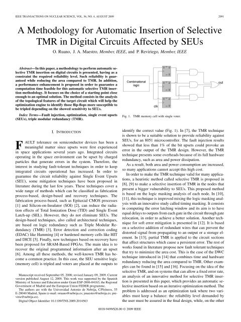
Fig. 1. TMR memory cell with single voter.<br />
I. INTRODUCTION<br />
F<br />
AULT tolerance on semiconductor devices has been a<br />
meaningful matter since upsets were first experienced<br />
in space applications several years ago. Integrated circuits<br />
operating in the space environment can be upset by charged<br />
particles that generate errors in the system. There<strong>for</strong>e, the<br />
interest in studying fault-tolerant techniques in order to keep<br />
integrated circuits operational has increased. In order to<br />
guarantee the circuit reliability against Single Event Upsets<br />
(SEU), some mitigation techniques have been proposed in<br />
literature during the last few years. These techniques cover a<br />
wide range <strong>of</strong> methods which can be classified as fabrication<br />
process-based, design-based and recovery techniques. The<br />
fabrication process-based, such as Epitaxial CMOS processes<br />
[1] and Silicon-on-Insulator (SOI) [2], can reduce the radiation<br />
effects <strong>of</strong> Total Ionization Dose (TID) and Single Event<br />
Latch-up (SEL). However, they do not eliminate SEUs. The<br />
design-based techniques, also called architectural techniques,<br />
are based on logic redundancy such as Triple Modular Redundancy<br />
(TMR) [3], Error detection and correction coding<br />
(EDAC) like Hamming [4] or hardened memory cells like HIT<br />
and DICE [5]. Finally, new techniques based on recovery have<br />
been proposed <strong>for</strong> SRAM-Based FPGAs. The main idea is to<br />
recover the original programmed in<strong>for</strong>mation after an upset<br />
[6]. Among all these methods, the well-known TMR has become<br />
a common practice. In this case, the SEU sensitive logic<br />
(memory cell) is tripled and voters are placed at the outputs to<br />
Manuscript received September 05, 2008; revised January 09, 2009. Current<br />
version published August 12, 2009. This work was supported by the Spanish<br />
Ministry <strong>of</strong> Science and Education under Grant ESP-2006-04163, the Regional<br />
Government <strong>of</strong> Madrid and the European Union FEDER programme.<br />
The authors are with the Universidad Antonio de Nebrija, C/Pirineos, 55<br />
E-28040 Madrid, Spain (e-mail: oruano@nebrija.es; jmaestro@nebrija.es; previrie@nebrija.es).<br />
Digital Object Identifier 10.1109/TNS.2009.2014563<br />
identify the correct value (Fig. 1). In [7], the TMR technique<br />
is shown to be a suitable solution to provide reliability against<br />
SEUs, <strong>for</strong> an 8051 microcontroller. The fault injection results<br />
showed that less than 1% <strong>of</strong> the bit upsets could provoke an<br />
error in the output <strong>of</strong> the TMR design. However, the TMR<br />
technique presents some overheads because <strong>of</strong> its full hardware<br />
redundancy, such as area and power dissipation.<br />
As a result, both area and power consumption are increased,<br />
so many applications cannot accept this high cost.<br />
In order to make the TMR technique valid <strong>for</strong> many applications,<br />
a heuristic method called selective TMR is proposed in<br />
[8], [9] to make a selective insertion <strong>of</strong> TMR in the nodes that<br />
present a bigger vulnerability to SEUs. This proposed method<br />
is based on the logic masking analysis <strong>of</strong> each node. In [10],<br />
[11], this technique is improved mixing the logic masking analysis<br />
with an innovative study called timing masking. It consists<br />
in computing the error latching window and its aim is to have<br />
equal delays to outputs from each gate in the circuit through gate<br />
relocation, in order to achieve a better solution. Another technique<br />
<strong>for</strong> s<strong>of</strong>t error mitigation is presented in [12]. It is based<br />
on a selective addition <strong>of</strong> redundant wires that can prevent the<br />
distorted signal from propagating to an output or a storage element.<br />
In [13], partial TMR is applied to the circuit sections<br />
that affect structures which cause a persistent error. The rest <strong>of</strong><br />
works found in literature propose new fault tolerant techniques<br />
that try to minimize the area cost. This is the case <strong>of</strong> the DWC<br />
technique introduced in [14] that combines time and hardware<br />
redundancy reducing the area compared to TMR. Other examples<br />
can be found in [15] and [16]. Focusing on the idea <strong>of</strong> the<br />
selective TMR, and on systems that can allow a fixed error rate,<br />
an analysis <strong>of</strong> an innovative method <strong>for</strong> selective TMR insertion<br />
is presented in this paper, which provides an automatic selective<br />
insertion based on an iterative optimization method. The<br />
problem is addressed as an optimization task where two variables<br />
must keep a balance: the reliability level demanded by<br />
the user must be assured in the final design, while, on the other<br />
0018-9499/$26.00 © 2009 <strong>IEEE</strong>
2092 <strong>IEEE</strong> TRANSACTIONS ON NUCLEAR SCIENCE, VOL. 56, NO. 4, AUGUST 2009<br />
Fig. 2.<br />
<strong>Methodology</strong> workflow.<br />
hand, the area cost due to the modular redundancy must be minimized.<br />
This paper is organized as follows. Section II introduces<br />
the proposed methodology <strong>for</strong> TMR optimization and explains<br />
in detail the major factors that are involved. In Section III, a<br />
tri-state pipeline stage is used as a case study where the methodology<br />
is validated by fault injection experiments in VHDL. In<br />
Section IV, the methodology is supplemented by an innovative<br />
static analysis process which enhances the per<strong>for</strong>mance <strong>of</strong> the<br />
optimization process. In Section V, the different criteria are analyzed<br />
experimentally via fault injection. Section VI shows in<br />
detail the previous case study with the enhancement integrated<br />
in the method. Final remarks and future work are placed in Section<br />
VII, followed by the references.<br />
II. PROPOSED METHODOLOGY<br />
Currently, the design <strong>of</strong> radiation tolerant circuits is very expensive<br />
in terms <strong>of</strong> area and power consumption if the Triple<br />
Modular Redundancy (TMR) technique is applied. There<strong>for</strong>e,<br />
this work proposes a selective TMR insertion adapted to the<br />
fault tolerance level required by the application. Although TMR<br />
clearly provides a superior protection level, not all the applications<br />
demand the highest fault tolerance level. In some cases,<br />
an intermediate protection could be enough, what makes TMR<br />
excessive in terms <strong>of</strong> area cost. The proposed methodology is<br />
based on a combinatorial optimization problem which makes<br />
use <strong>of</strong> the reliability constraints that the target circuit has to<br />
meet. The issue is addressed like a graph partitioning problem<br />
which is included in the category <strong>of</strong> NP-complete problems. It<br />
consists in partitioning a given initial graph which includes all<br />
registers <strong>of</strong> the initial circuit, in two sub-graphs. One <strong>of</strong> them,<br />
stores the registers that the system has chosen to protect with<br />
TMR, and the second stores the remaining registers without<br />
TMR. The purpose <strong>of</strong> this methodology is to find the best partition<br />
that assures the minimum possible area in terms <strong>of</strong> the<br />
number <strong>of</strong> registers on which TMR is inserted, while meeting<br />
the reliability constrains specified <strong>for</strong> the circuit. There<strong>for</strong>e, the<br />
optimization process looks <strong>for</strong> a solution among a finite set <strong>of</strong><br />
alternative results which minimizes the area and assures the required<br />
reliability. The methodology workflow defined to drive<br />
the process is described in Fig. 2.<br />
The operational method is detailed next. First <strong>of</strong> all, data<br />
inputs required by the methodology must include an original<br />
VHDL description, a random initial partition <strong>of</strong> the registers<br />
grouped into two sub-graphs and the fault tolerance constraints<br />
required by the application. Once these data are available, the<br />
methodology is able to obtain a valid partition which can satisfy<br />
the specified reliability constraints. The first step consists<br />
in measuring the fault tolerance <strong>for</strong> the random initial partition<br />
in order to evaluate it and see if it is a valid solution or not. In<br />
order to achieve this objective, the process is detailed next. The<br />
original VHDL and the set <strong>of</strong> registers with TMR are given to<br />
the <strong>Selective</strong> TMR insertion module in order to insert TMR on<br />
the appropriate registers. Next, the modified VHDL is used to<br />
per<strong>for</strong>m a fault injection campaign using the SEU Simulation<br />
Tool [17], [18]. The fault tolerance level <strong>of</strong> the modified VHDL<br />
is reported by the fault injection results through s<strong>of</strong>tware fault<br />
injection [19]. These results are sent to the optimization engine<br />
module which evaluates them against the reliability constraints<br />
required by the application. Once the initial partition has been<br />
measured, the above process is repeated with a new partition <strong>of</strong><br />
the registers selected by the optimization engine, which manages<br />
the remaining possible partitions through an optimization<br />
algorithm. For each new partition driven by the optimization algorithm,<br />
the <strong>Selective</strong> TMR <strong>Insertion</strong> module modifies the original<br />
VHDL and a new fault injection is run to evaluate the new<br />
tolerance. The process is finished when the optimization engine
RUANO et al.: A METHODOLOGY FOR AUTOMATIC INSERTION OF SELECTIVE TMR IN DIGITAL CIRCUITS AFFECTED BY SEUS 2093<br />
cannot find a new partition with less area cost that satisfies the<br />
demanded reliability. In the following, some issues which can<br />
have impact in the proposed methodology are discussed.<br />
A. Optimization Algorithm<br />
In order to guide the successive movements and the several<br />
partitions which are tested through the fault injection process,<br />
an iterative algorithm has been selected to per<strong>for</strong>m the experimental<br />
results. Fiduccia-Mattheyses [20] is the meta-heuristic<br />
algorithm which has been chosen due to its widely use in literature.<br />
A final solution is achieved by moving one register at a<br />
time, <strong>for</strong> one graph <strong>of</strong> the partition to the other, updating the partition<br />
in each step. Another feature <strong>of</strong> this algorithm is that it reduces<br />
the chance that the minimization process becomes trapped<br />
at local minima (hill-climbing) [20]. In an attempt to reduce the<br />
number <strong>of</strong> registers with TMR while satisfying the reliability<br />
constraints, it drives the intermediate partitions according to a<br />
cost function which will determine if each partition can satisfy<br />
the reliability constraints or not.<br />
B. Cost Function<br />
The cost function must drive the algorithm in order<br />
to accept or deny each movement that is proposed by<br />
Fiduccia-Mattheyses in the search space. This cost function<br />
is included in the minimization problem in the following<br />
way.<br />
— Given: a function .<br />
— Sought: an element in such that <strong>for</strong> all<br />
in .<br />
The domain <strong>of</strong> is called the search space, while the elements<br />
<strong>of</strong> are called candidate solutions or valid solutions. A<br />
valid solution that minimizes the objective function is called an<br />
optimal solution. With these premises, the selective TMR insertion<br />
issue can be characterized in the following way.<br />
— represents all possible partitions which can be generated<br />
from the whole set <strong>of</strong> registers that compose the design<br />
under test.<br />
— represents a valid solution, i.e., a partition composed<br />
by two sub-graphs in which the first contains the selected<br />
registers to protect with TMR and the second the rest <strong>of</strong><br />
registers without TMR that meets the specified reliability<br />
constraints.<br />
All valid solutions must satisfy a specified set <strong>of</strong> constraints. In<br />
our case, a set <strong>of</strong> reliability constraints on the circuit outputs<br />
are used. Consequently, in order to measure the quality <strong>of</strong> a solution<br />
according to the parameters <strong>of</strong> the problem (number <strong>of</strong><br />
registers, reliability constraints and real error rate obtained by<br />
the fault injection), the next cost function has been defined so<br />
that combines all these parameters<br />
# #<br />
#<br />
#<br />
where #registers is the total number <strong>of</strong> register that composes<br />
the currently partition, the number <strong>of</strong> errors<br />
detected in the output through the fault injection process,<br />
is the error threshold that must be<br />
satisfied by each output and finally the coefficients, which<br />
represent the influence <strong>of</strong> each output. Currently, the cost<br />
function takes no account <strong>of</strong> the overhead <strong>of</strong> the majority voters<br />
in an explicit way because this factor is directly proportional to<br />
the number <strong>of</strong> tripled registers.<br />
C. Reliability Constraints<br />
Reliability constraints mentioned previously<br />
, are defined as the tolerance<br />
level which must be met by a valid solution in any case.<br />
These constraints are measured as the maximum percentage<br />
<strong>of</strong> wrong cycles allowed in each output <strong>of</strong> the target design.<br />
The optimization engine and more specifically the F cost<br />
function requires these parameters in order to accept or deny<br />
the movement <strong>of</strong> each register. These factors must be specified<br />
by the user as the tolerance thresholds which must be met<br />
by each output <strong>of</strong> the circuit and there<strong>for</strong>e, their choice is<br />
considered key <strong>for</strong> the optimization process. Depending on<br />
these constraints, the circuit can tolerate more or less failures,<br />
and as a result it will have a direct effect on the insertion <strong>of</strong><br />
selective TMR.<br />
D. Optimization Per<strong>for</strong>mance<br />
It is known that the runtime required to obtain a valid solution,<br />
<strong>for</strong> the chosen iterative algorithm, increases with the size<br />
<strong>of</strong> the problem. In some cases, the computation time can be so<br />
high that the heuristic method is not able to obtain accurate solutions<br />
in reasonable runtimes (too many registers). According<br />
to this issue, it is detected that the initial partition has a<br />
major influence to reduce the execution time <strong>of</strong> the method as it<br />
will be shown in the experimental results <strong>of</strong> the next section. In<br />
this case, a previous knowledge or a static analysis which reports<br />
in<strong>for</strong>mation <strong>of</strong> possible weak points <strong>of</strong> the circuit (Section IV)<br />
can improve the runtime per<strong>for</strong>mance. This would reduce the<br />
number <strong>of</strong> iterations, initiating the process from a selected initial<br />
partition close to a valid solution instead <strong>of</strong> a random initial<br />
partition. Also, from this in<strong>for</strong>mation, the cost function can<br />
be customized through the coefficients in order to prioritize<br />
those weak points identified as sensitive to SEUs, converging<br />
earlier to a solution. Finally, other kinds <strong>of</strong> algorithms can be<br />
used in order to make a per<strong>for</strong>mance comparison, like a greedy<br />
heuristic. Moreover, two heuristics can be studied to address<br />
the following two sources <strong>of</strong> complexity. The first one would<br />
consist <strong>of</strong> avoiding exhaustive simulation <strong>of</strong> all states combinations<br />
using sampling and the second one would be referred to<br />
reduce the search space, considering the addition <strong>of</strong> TMR on<br />
those flip-flops which reach a primary output with a high probability<br />
[21], [22].<br />
For this work, all these points have been taken into account in<br />
the next section in order to present experimental results which<br />
optimize the insertion <strong>of</strong> TMR in a selective way ( , reliability<br />
constraints and coefficients).<br />
III. CASE STUDY<br />
In order to verify the proposed methodology, a case study is<br />
analyzed in this section. The circuit under test computes the sum
2094 <strong>IEEE</strong> TRANSACTIONS ON NUCLEAR SCIENCE, VOL. 56, NO. 4, AUGUST 2009<br />
Fig. 3.<br />
Tri-state pipeline stage.<br />
TABLE I<br />
AUTOMATIC INSERTION OF SELECTIVE TMR FOR AREA EFFICIENCY<br />
<strong>of</strong> three 8-bit data buses , and , that is to say<br />
, and and supplies the results on a single 9-bit output<br />
bus in three consecutive clock cycles. Also, an extra output control<br />
signal (OutDataReady) should be active <strong>for</strong> one clock cycle<br />
to indicate when the three summed outputs are available. The<br />
proposed design (54 flip-flops) is shown in Fig. 3 [23].<br />
The proposed methodology has been applied to this circuit<br />
in order to obtain results <strong>of</strong> the automatic insertion <strong>of</strong> selective<br />
TMR. Experimental results are collected in Table I, where three<br />
different scenarios regarding the requested tolerance (0, 0, 5, and<br />
1 per cent respectively) have been proposed in order to show the<br />
area decrease compared to TMR. Also, <strong>for</strong> each reliability scenario,<br />
three different tests have been proposed where the initial<br />
partitions are changed in order to study how the method per<strong>for</strong>mance<br />
can vary in terms <strong>of</strong> the explored solutions. The reliability<br />
constraint has been considered only <strong>for</strong> the Y output as all<br />
registers <strong>of</strong> the system have effect on it, included those which<br />
determine the value <strong>of</strong> the OutDataReady output. All tests have<br />
run simulations <strong>of</strong> 100 000 clock cycles injecting random campaigns<br />
<strong>of</strong> 10 000 SEUs with a minimum separation <strong>of</strong> 3 cycles<br />
between two consecutive ones. These results allow a comparison<br />
with the area cost <strong>of</strong> the standard TMR approach (Table I).
RUANO et al.: A METHODOLOGY FOR AUTOMATIC INSERTION OF SELECTIVE TMR IN DIGITAL CIRCUITS AFFECTED BY SEUS 2095<br />
With these results, it can be noticed that in the cases where<br />
the application does not demand the highest fault tolerance level<br />
(<strong>for</strong> example 0,5% or 1%), an intermediate protection could be<br />
enough to satisfy the reliability constraints, reducing the area<br />
cost in terms <strong>of</strong> flip-flops (29.6% and 40.7% respectively) compared<br />
to the standard TMR approach.<br />
On the other hand, an interesting result <strong>of</strong>fered by the methodology<br />
consists in the detection <strong>of</strong> critical nodes which show<br />
a bigger vulnerability to SEUs like in the case <strong>of</strong> the control<br />
flip-flops<br />
. In all tests,<br />
these registers have been tripled with a high priority in order<br />
to achieve the fault tolerance needed. In this way, the<br />
illustrated in Table I <strong>for</strong> tolerances <strong>of</strong> 0, 5, and 1% has included<br />
in all cases these control registers in the TMR sub-graph,<br />
and in second place the and Y registers were also<br />
added. Finally, it also should be noticed that the initial partition<br />
is a significant factor in order to improve the per<strong>for</strong>mance<br />
<strong>of</strong> the process. In this way, an innovative analysis based on the<br />
topology <strong>of</strong> the circuit will complete the optimization methodology<br />
in the next section, in order to select the best initial partition.<br />
This will reduce the number <strong>of</strong> searches required by the<br />
engine. Table I emphasizes that when beginning from a partition<br />
near to the final solution, a small number <strong>of</strong> searches is required.<br />
For example, in the case <strong>of</strong> 0% tolerance in order to achieve the<br />
same (54-0), starting from a partition without any register<br />
tripled (0-54) 103 explorations are required while using a better<br />
partition, like (26-28) or the best (54-0), 58 and 12 are needed<br />
respectively, improving the per<strong>for</strong>mance considerably.<br />
These results can be contrasted with an analysis <strong>of</strong> the circuit.<br />
As it has been said, in all final partitions the control flipflops<br />
have been included. This means that these flip-flops are<br />
considered more sensitive to SEUs by the process. An SEU<br />
in these flip-flops can alter significantly the good behavior <strong>of</strong><br />
the circuit being able to propagate the error during three cycles<br />
in the worst case (SEU on InDataReady flip-flop). The right<br />
functionality is only recovered when the SEU goes out <strong>of</strong> the<br />
delay line <strong>of</strong> the control path<br />
. On the other hand,<br />
, and data registers are considered<br />
less sensitive because they refresh the useful data each<br />
cycle and also are used <strong>of</strong> the cycles, so an SEU can be observed<br />
at the output or it cannot affect the output value. So, these<br />
registers usually have not been tripled by the system due to the<br />
low probability <strong>of</strong> observing an SEU in the Y output. Nevertheless,<br />
an SEU in the remaining registers and<br />
will be observed in all cases but only during one cycle. With this<br />
analysis, it has been proved why the methodology firstly triplicates<br />
control registers, secondly and Y, and finally, if<br />
it does not satisfy the reliability constraints yet, the rest <strong>of</strong> registers.<br />
IV. PERFORMANCE ENHANCEMENT: SELECTION OF THE<br />
INITIAL PARTITION<br />
In the previous section, it could be noticed the importance <strong>of</strong> a<br />
good initial partition <strong>for</strong> a successful optimization process. This<br />
factor is used as an input <strong>for</strong> the optimization engine and it has<br />
been demonstrated that it has a direct influence on the per<strong>for</strong>mance<br />
<strong>of</strong> the methodology. Depending on the initial partition,<br />
the optimization process can reach the best solution exploring<br />
more or less partial solutions, as it is shown in Table I. So, as the<br />
computational time depends on the circuit size, this can cause<br />
an unacceptable computational time. In order to mitigate this<br />
weakness, an enhancement will be presented and studied in an<br />
experimental way, validating it and later integrating it into the<br />
workflow, as it is shown in Fig. 4.<br />
In this figure, a new module has been included to improve the<br />
per<strong>for</strong>mance. It drives the selection process in order to choose<br />
the best starting point <strong>for</strong> the optimization engine. This method<br />
is based on an intuitive topological analysis <strong>of</strong> the target circuit,<br />
which is able to improve the computational time. The output <strong>of</strong><br />
this module is a suggested initial partition which is supposed to<br />
be close enough to the final solution so that the computation time<br />
is feasible, reducing the ef<strong>for</strong>t <strong>of</strong> the optimization algorithm. In<br />
Fig. 5, this idea is illustrated. Given a search space, the goal <strong>of</strong><br />
the proposed enhancement is not to look <strong>for</strong> the optimal solution<br />
(S) (this is the task <strong>of</strong> the optimization engine), but an approximation<br />
(D) which can reduce the number <strong>of</strong> steps needed<br />
to get the solution. With this, it is possible to partly reduce the<br />
dependence between the computational time and the size <strong>of</strong> the<br />
circuit.<br />
As it has been said above, the way to obtain an initial partition<br />
close to the optimal solution is based on the topological analysis<br />
<strong>of</strong> the flip-flops in the circuit. In order to do this, some topological<br />
criteria have been chosen to study how they can influence<br />
the correct behavior <strong>of</strong> the circuit in the presence <strong>of</strong> SEUs.<br />
These criteria have been analyzed experimentally <strong>for</strong> several circuit<br />
samples, allowing to draw conclusions about their relation<br />
to SEU sensitiveness. In other words, by examining these criteria,<br />
it will be possible to identify those flip-flops which are<br />
‘hot spots’ against SEUs. There<strong>for</strong>e, the proposed approach allows<br />
labeling this group <strong>of</strong> flip-flops as candidates to be part <strong>of</strong><br />
Graph 1 <strong>of</strong> the start partition (tripled registers) (Fig. 4).<br />
In order to characterize each flip-flop according to the criteria,<br />
the circuit is considered as a finite directed graph on vertices<br />
(flip-flops) where its adjacency matrix is used to represent the<br />
connectivity <strong>of</strong> the different nodes (Fig. 6) [24].<br />
The adjacency matrix is the matrix where each no-diagonal<br />
entry is a direct connection from flip-flop to flip-flop<br />
, and each diagonal entry is the feedback or loop at flip-flop<br />
. In the following, a set <strong>of</strong> topological criteria are chosen, allowing<br />
the characterization <strong>of</strong> each flip-flop. They have been<br />
described and finally analyzed, <strong>for</strong> a wide space <strong>of</strong> circuit samples,<br />
which allow estimating their relevance in a statistical way.<br />
A. FAN-IN Input Parameter<br />
This parameter refers to the number <strong>of</strong> flip-flops which have<br />
influence on the state <strong>of</strong> the analyzed flip-flop. The main reason<br />
to use this characteristic is the fact that the greater the number<br />
<strong>of</strong> inputs which drive the flip-flop state is, the less likely that an<br />
SEU can be stored in it. This is because the effect <strong>of</strong> the distorted<br />
value can be masked by the rest <strong>of</strong> inputs. On the other hand, if<br />
there is only one input that drives the target flip-flop and it is<br />
distorted, the SEU will be stored always. So, depending on the<br />
number <strong>of</strong> inputs <strong>of</strong> the implemented function, the flip-flop can<br />
be more or less tolerant to SEUs [8].<br />
Algorithm 1 is implemented in order to measure this attribute<br />
on a given topology.
2096 <strong>IEEE</strong> TRANSACTIONS ON NUCLEAR SCIENCE, VOL. 56, NO. 4, AUGUST 2009<br />
Fig. 4. <strong>Methodology</strong> workflow with the added enhancement.<br />
Algorithm 1: input criterion (Adjacency Matrix)<br />
Function: input criterion (Adjacency Matrix)<br />
Input: Adjacency Matrix,<br />
Foreach<br />
(Find<br />
(R) do<br />
Foreach<br />
(R) do<br />
Return C2<br />
Return C1<br />
B. FAN-OUT Output Parameter<br />
This parameter refers to the number <strong>of</strong> flip-flops which are affected<br />
directly by the state <strong>of</strong> each analyzed flip-flop. The main<br />
reason to decide on this characteristic is because an SEU in a<br />
flip-flop which propagates its state to several paths has a high<br />
probability <strong>of</strong> affecting any design output, and there<strong>for</strong>e its observability<br />
is increased. Algorithm 2 is implemented in order to<br />
measure this attribute:<br />
Algorithm 2: output criterion (Adjacency Matrix)<br />
Function: output criterion (Adjacency Matrix)<br />
Input: Adjacency Matrix,<br />
C. Influence on Output Paths<br />
This parameter refers to the number <strong>of</strong> primary outputs which<br />
are affected by the analyzed flip-flop. The main reason to take<br />
this issue into account, is the fact that an SEU in a flip-flop belonging<br />
to more than one output path, has a higher probability to<br />
propagate the error to at least one <strong>of</strong> these outputs, increasing its<br />
observability. Algorithm 3 is implemented in order to measure<br />
this attribute, using the Dijkstra’s algorithm, which is <strong>of</strong>ten used<br />
in computer networks [25], [26]. It is a graph search algorithm<br />
that solves the single-source shortest path problem <strong>for</strong> a graph.<br />
In this case Dijkstra’s algorithm is used to find the number <strong>of</strong><br />
outputs which are linked to each evaluated flip-flop. When Dijkstra<br />
returns a path between the flip-flop and the output, it means<br />
that there is connectivity.<br />
Algorithm 3: Influence output criterion (Adjacency<br />
Matrix)<br />
Function: Influence output criterion (Adjacency Matrix)
RUANO et al.: A METHODOLOGY FOR AUTOMATIC INSERTION OF SELECTIVE TMR IN DIGITAL CIRCUITS AFFECTED BY SEUS 2097<br />
Fig. 5. Selecting the initial partition: partition (A) All TMR partition; (B) None TMR partition; (C) Random partition; (D) Based on topological analysis; S)<br />
Optimal Solution.<br />
Function: proximity output criterion (Adjacency Matrix)<br />
Input: Adjacency Matrix,<br />
Foreach<br />
(R) do<br />
Fig. 6.<br />
Adjacency matrix example.<br />
Foreach<br />
(O) do<br />
Input: Adjacency Matrix,<br />
Foreach<br />
(R) do<br />
// take the minimum distance among all affected<br />
outputs<br />
Foreach<br />
(O) do<br />
Return C4<br />
Return C3<br />
If (dijkstra<br />
D. Proximity to the Outputs<br />
This parameter refers to the proximity <strong>of</strong> the evaluated<br />
flip-flop to the outputs which are affected by it. The main<br />
reason to take this criterion into account is the fact that depending<br />
on the distance to the output, an SEU can have a lower<br />
or higher probability to be masked. It is due to factors like<br />
masking logic, timing logic and so on [10], [11]. An SEU in a<br />
flip-flop with a greater distance to the output is more likely to<br />
be masked. Algorithm 4 is implemented in order to measure<br />
this attribute, using Dijkstra’s algorithm. In this case, it is used<br />
to find the shortest path between each evaluated flip-flop and<br />
all other circuit outputs affected by them.<br />
E. Feedback Loops<br />
This parameter refers to the situation in which the output<br />
signal <strong>of</strong> a flip-flop is passed (fed back) to its input, directly<br />
or through several previous stages. This is <strong>of</strong>ten used to control<br />
the dynamic behavior <strong>of</strong> the system. The main reason to take<br />
this criterion into account is the fact that an SEU in this type<br />
<strong>of</strong> flip-flop (with feedback) can be stored in the loop, making<br />
the effect <strong>of</strong> the SEU permanent. Algorithm 5 is implemented<br />
in order to measure this attribute, using the same Dijkstra algorithm.<br />
In this case, the direct outputs <strong>of</strong> the target flip-flop<br />
are identified and from each one, Dijkstra algorithm looks <strong>for</strong><br />
the shortest path to the target flip-flop. If this path is found, it<br />
means that there is a loop.<br />
Algorithm 5: feedback criterion (Adjacency Matrix)<br />
Function: feedback criterion (Adjacency Matrix)<br />
Input: Adjacency Matrix,<br />
Foreach<br />
(R) do<br />
Algorithm 4: proximity output criterion (Adjacency<br />
Matrix)<br />
Foreach<br />
do
2098 <strong>IEEE</strong> TRANSACTIONS ON NUCLEAR SCIENCE, VOL. 56, NO. 4, AUGUST 2009<br />
Fig. 7. Criteria Summary. Dark grey node: More sensitive FF, Light grey node: Less sensitive FF. (A) Input parameter. (B) Output parameter. (C) Influence on<br />
output paths.(D) Proximity to the output. (E) Feedback loop.<br />
// Count the feedback paths<br />
If<br />
to the explained criteria. These criteria will be analyzed experimentally<br />
through fault injection in the following section, in<br />
order to validate the expected behaviors.<br />
Finally, these algorithms have been implemented in order<br />
to obtain, in an automatic way, a criteria matrix, where each<br />
flip-flop is quantified <strong>for</strong> each <strong>of</strong> these criteria.<br />
V. EXPERIMENTAL ANALYSIS OF THE CRITERIA<br />
Return C5<br />
In Fig. 7, a summary <strong>of</strong> the criteria which have been introduced<br />
in this section is shown. In each example, the expected<br />
behavior <strong>of</strong> the highlighted target flip-flops is estimated against<br />
the injection <strong>of</strong> SEUs through a color code. Dark grey nodes are<br />
expected to be more sensitive than light grey nodes according<br />
In this section, the behavior <strong>of</strong> each criterion is verified experimentally,<br />
in order to guarantee the explained logic principles <strong>of</strong><br />
the previous section. A set <strong>of</strong> specific circuits have been used to<br />
make the fault injection and prove the expected behavior. These<br />
circuits have been selected in order to measure the influence <strong>of</strong><br />
each criterion independently (Fig. 7). Next, the obtained results<br />
achieved through fault injection are shown in Figs. 8 to 12. The<br />
results illustrate the number <strong>of</strong> error cycles observed at the outputs<br />
(Y axis) after having injected 1000 SEUs per register.
RUANO et al.: A METHODOLOGY FOR AUTOMATIC INSERTION OF SELECTIVE TMR IN DIGITAL CIRCUITS AFFECTED BY SEUS 2099<br />
Fig. 8. Experimental analysis <strong>of</strong> FAN-IN.<br />
Fig. 9. Experimental analysis <strong>of</strong> FAN-OUT.<br />
All these graphics represent the value <strong>of</strong> the associated<br />
criterion versus the measured error rate (wrong cycles/injected<br />
SEUs). With these results, it can be noticed that in all cases<br />
the behavior <strong>of</strong> the criteria corresponds with the expected one,<br />
explained in the previous section.<br />
For the first criterion (fan-in), the trend is to decrease the error<br />
rate when the number <strong>of</strong> inputs that drive the flip-flop increases.<br />
In this case, it can be concluded that a flip-flop with a higher<br />
fan-in should not be tripled.<br />
For criteria 2 and 3, the trend is to increase the error rate according<br />
to the increment <strong>of</strong> the number <strong>of</strong> paths/outputs respectively.<br />
In this case, it can be concluded that a flip-flop with a<br />
larger fan-out is susceptible to be tripled.<br />
For criterion 4, the experimental results meet the expected<br />
behavior too. In this case, it can be observed that depending on<br />
the distance <strong>of</strong> the injected flip-flop to one primary output, the<br />
measured error rate increases. This is due to the filter capacity<br />
<strong>of</strong> the masking logic. In this case, it can be concluded that a<br />
flip-flop which is far from a primary output is not convenient<br />
to be tripled. Finally <strong>for</strong> the last criterion (feedback loop), the<br />
experimental results show a bigger vulnerability <strong>for</strong> those flipflops<br />
that have larger feedback loops against others with smaller<br />
loops or the simple case without any loop. So it can be concluded<br />
that a flip-flop with feedback loops is more convenient to be<br />
tripled, depending on the size <strong>of</strong> the loop. As a result, taking<br />
into account the knowledge <strong>of</strong> the behavior against SEUs <strong>for</strong><br />
all these common topological features, they can be used in an<br />
automatic way to propose an initial partition which is able to<br />
reduce the search space, thus improving the efficiency <strong>of</strong> the<br />
methodology.<br />
VI. QUALITY ANALYSIS OF THE ENHANCED TECHNIQUE<br />
In order to verify the proposed enhancement, the same case<br />
study <strong>of</strong> Section III, is analyzed adding the criteria analysis. The
2100 <strong>IEEE</strong> TRANSACTIONS ON NUCLEAR SCIENCE, VOL. 56, NO. 4, AUGUST 2009<br />
Fig. 10. Experimental analysis <strong>of</strong> the influence on output paths.<br />
Fig. 11.<br />
Experimental analysis <strong>of</strong> the proximity to the output.<br />
objective is to prove how the selection <strong>of</strong> a good initial partition,<br />
based on the mentioned criteria, can improve the efficiency <strong>of</strong><br />
the optimization method. Now, <strong>for</strong> each reliability scenario proposed<br />
in Table I (0%, 0,5%, 1%) a similar test has been per<strong>for</strong>med,<br />
where the only difference is the initial partition which<br />
is chosen according to the previous criteria set. To accomplish<br />
this, the algorithm set introduced in Section IV has been implemented<br />
in order to obtain a criteria matrix where the values <strong>of</strong><br />
the criteria <strong>for</strong> each flip-flop are calculated. On this criteria matrix,<br />
once all flip-flops have been characterized, an algorithm has<br />
been applied in order to select those flip-flops which meet the<br />
next requirement. Any flip-flop is considered sensitive to SEUs<br />
if<br />
— at least one <strong>of</strong> the criteria C2, C3 or C5 has the maximum<br />
value;<br />
— the value <strong>of</strong> criterion C4 is high and has to affect at least a<br />
high-priority output;<br />
— the value <strong>of</strong> criterion C1 is not high.<br />
Applying these constraints, the following initial partition has<br />
been chosen by the automatic algorithm<br />
With TMR<br />
Without TMR .<br />
Next, this initial partition will be justified following the previous<br />
criteria. For A hold, Indataready delay, Enb, and Enc, the<br />
reason is because they have the maximum fan-out value. In addition,<br />
Indataready delay, Enb, and Enc affect the two primary<br />
outputs <strong>of</strong> the system, and there<strong>for</strong>e they are triplicated. For<br />
Ena delay, M delay and Out delay, the proximity to the primary
RUANO et al.: A METHODOLOGY FOR AUTOMATIC INSERTION OF SELECTIVE TMR IN DIGITAL CIRCUITS AFFECTED BY SEUS 2101<br />
Fig. 12.<br />
Experimental analysis <strong>of</strong> the feedback loop.<br />
TABLE II<br />
COMPARISON OF PARTIAL SOLUTIONS EXPLORED WITH OR WITHOUT ENHANCEMENT<br />
output has been useful. Ena delay is selected because its cost <strong>of</strong><br />
triplication is lower than A delay, which has the same value <strong>for</strong><br />
criterion C4, but it is <strong>for</strong>med by more flip-flops. The rest <strong>of</strong> registers<br />
make up the no-TMR sub-graph. For example Ena has a<br />
higher fan-in so the first criterion (fan-in) makes it unnecessary<br />
to be tripled.<br />
Finally, this initial partition has been used to per<strong>for</strong>m the optimization<br />
process again on the case study. In Table II the experimental<br />
results with this new partition (29–25) are shown, in<br />
order to compare the use <strong>of</strong> the topological criteria versus the<br />
use <strong>of</strong> trivial initial partitions.<br />
With these results, it can be concluded that this methodology<br />
helps the optimization engine to improve its efficiency,<br />
obtaining the same results in terms <strong>of</strong> cost as that in Table I<br />
(final partition). The only case where the technique does not<br />
improve the per<strong>for</strong>mance is the specific situation where 0% <strong>of</strong><br />
wrong cycles are required. In this case, it is clear that starting<br />
with all registers in TMR would be faster. Nevertheless, if a<br />
certain degree <strong>of</strong> fault tolerance is allowed, which is the usual<br />
situation in real applications, using the topological criteria to<br />
find a good initial partitioning is the most convenient approach.<br />
For this example, the search space is rather small and there<strong>for</strong>e<br />
per<strong>for</strong>mance has been improved by a small margin. But <strong>for</strong><br />
larger designs, this technique would be able to provide higher<br />
time savings by finding an initial partition closer to the optimal<br />
solution.<br />
VII. CONCLUSIONS AND FUTURE WORK<br />
In this paper, a new methodology to insert selective TMR <strong>for</strong><br />
SEU mitigation has been presented. The benefits <strong>of</strong> applying the<br />
automatic selective TMR methodology are clearly proved with<br />
the experimental results that have been obtained: the technique<br />
results in a lower circuit complexity than the traditional TMR<br />
approach, while meeting the specified reliability level. Besides,<br />
this methodology has been improved in terms <strong>of</strong> per<strong>for</strong>mance,<br />
adding an enhancement based on an innovative topological analysis<br />
<strong>of</strong> the target circuit. The benefit <strong>of</strong> this approach has been<br />
verified through fault injection experiments. This improvement<br />
results in a reduction <strong>of</strong> the number <strong>of</strong> explored partial solutions<br />
by the optimization engine, due to the calculation <strong>of</strong> an initial<br />
partition close enough to the optimal solution.<br />
The next steps will focus on the study <strong>of</strong> these criteria in<br />
general purpose circuits and real space circuits like SpaceWire<br />
[27]. Also, a more sophisticated model that studies all the calculated<br />
criteria and automatically produces the set <strong>of</strong> conditions<br />
to initially map or not any given flip-flop in TMR will be produced.<br />
Finally the study <strong>of</strong> other optimization algorithms (simulated<br />
annealing, genetic, mimetic, adaptive), and alternative cost<br />
functions that can be adapted prioritizing the influence <strong>of</strong> each<br />
output will be carried out.
2102 <strong>IEEE</strong> TRANSACTIONS ON NUCLEAR SCIENCE, VOL. 56, NO. 4, AUGUST 2009<br />
REFERENCES<br />
[1] Y. Moreau, S. Duzellier, and J. Gasiot, “Evaluation <strong>of</strong> the upset risk in<br />
CMOS SRAM through full three dimensional simulation,” <strong>IEEE</strong> Trans.<br />
Nucl. Sci., vol. 42, no. 6, pt. 1, pp. 1789–1796, Dec. 1995.<br />
[2] F. Irom, F. F. Farmanesh, A. H. Johnston, G. M. Swift, and D. G.<br />
Millward, “Single-event upset in commercial silicon-on-insulator PowerPC<br />
microprocessors,” <strong>IEEE</strong> Trans. Nucl. Sci., vol. 49, no. 6, pt. 1, pp.<br />
3148–3155, Dec. 2002.<br />
[3] C. Carmichael, “Triple modular redundancy design techniques <strong>for</strong><br />
virtex series FPGA,” presented at the Application Notes 197, San Jose,<br />
CA, 2000, Xilinx.<br />
[4] R. Hentschke, F. Marques, F. Lima, L. Carro, A. Susin, and R. Reis,<br />
“Analysing area an per<strong>for</strong>mance penalty <strong>of</strong> protecting different digital<br />
modules with hamming code and triple modular redundancy,” presented<br />
at the Symp. Integrated Circuits and Systems Design, Proceedings,<br />
Sep. 2002.<br />
[5] R. Velazco, D. Bessot, S. Duzellier, R. Ec<strong>of</strong>fet, and R. Koga, “Two<br />
CMOS memory cells suitable <strong>for</strong> the design <strong>of</strong> SEU-tolerant VLSI circuits,”<br />
<strong>IEEE</strong> Trans. Nucl. Sci., vol. 41, no. 6, pt. 1, pp. 2229–2234, Dec.<br />
1994.<br />
[6] L. Sterpone and M. Violante, “A new partial reconfiguration-based<br />
fault-injection system to evaluate SEU effects in SRAM-based<br />
FPGAs,” <strong>IEEE</strong> Trans. Nucl. Sci., vol. 54, no. 4, pt. 2, pp. 965–970,<br />
Aug. 2007.<br />
[7] F. Lima, S. Rezgui, E. Cota, L. Carro, M. Lubaszewski, R. Reis, and R.<br />
Velazco, “Designing a radiation hardened 8051-like micro-controller,”<br />
in Proc. Symp. Integrated Circuits and Systems Design, Sep. 2000, pp.<br />
255–260.<br />
[8] P. K. Samudrala, J. Ramos, and S. Katkoori, “<strong>Selective</strong> triple modular<br />
redundancy (STMR) based single-event upset (SEU) tolerant synthesis<br />
<strong>for</strong> FPGAs,” <strong>IEEE</strong> Trans. Nucl. Sci., vol. 51, no. 10, pp. 2957–2969,<br />
Oct. 2004.<br />
[9] P. K. Samudrala, J. Ramos, and S. Katkoori, “Method and Apparatus<br />
<strong>for</strong> Creating Circuit Redundancy in Programmable Logic Devices,”<br />
U.S. Patent Pub. No. WO/2004/077260, Oct. 2004.<br />
[10] S. Krishnaswamy, S. M. Plaza, I. L. Markov, and J. P. Hayes, “Enhancing<br />
design robustness with realiability-aware resynthesis and logic<br />
simulation,” in Proc. Int. Conf. Computer Aided Design, pp. 149–154.<br />
[11] S. Krishnaswamy, I. L. Markov, and J. P. Hayes, “On the role <strong>of</strong> timing<br />
masking in reliable logic circuit design,” presented at the Design Automation<br />
Conf., 2008.<br />
[12] S. Almukhaizim and Y. Makris, “S<strong>of</strong>t error mitigation through selective<br />
addition <strong>of</strong> functionally redundant wires,” <strong>IEEE</strong> Trans. Rel., vol.<br />
57, no. 1, pp. 23–31, Mar. 2008.<br />
[13] B. Pratt, M. Caffrey, J. F. Carroll, P. Graham, K. Morgan, and M.<br />
Wirthlin, “Fine-grain SEU mitigation <strong>for</strong> FPGAs using partial TMR,”<br />
<strong>IEEE</strong> Trans. Nucl. Sci., vol. 55, no. 4, pt. 1, pp. 2274–2280, Aug. 2008.<br />
[14] F. Lima, G. Neuberger, R. Hentschke, L. Carro, and R. Reis, “Designing<br />
fault-tolerant techniques <strong>for</strong> SRAM-based FPGAs,” <strong>IEEE</strong> Des.<br />
Test Comput., vol. 21, no. 6, pp. 552–562, Nov.–Dec. 2004.<br />
[15] P. Reyes, P. Reviriego, J. A. Maestro, and O. Ruano, “New protection<br />
techniques against SEUs <strong>for</strong> moving average filters in a radiation environment,”<br />
<strong>IEEE</strong> Trans. Nucl. Sci., vol. 54, no. 4, pp. 957–964, Aug.<br />
2007.<br />
[16] O. Ruano, P. Reviriego, and J. A. Maestro, “A new EDAC technique<br />
against s<strong>of</strong>t errors based on pulse detectors,” presented at the <strong>IEEE</strong> Int.<br />
Symp. Industrial Electronics, Cambridge, U.K., Jun. 2008.<br />
[17] D. Gonzalez, Single Event Upset Simulation Tool Functional Description<br />
ESA Rep. TEC-EDM/DCC-SST2, Jul. 2004.<br />
[18] O. Ruano, J. A. Maestro, P. Reyes, and P. Reviriego, “A simulation<br />
plat<strong>for</strong>m <strong>for</strong> the study <strong>of</strong> s<strong>of</strong>t errors on signal processing circuits<br />
through s<strong>of</strong>tware fault injection,” in Proc. <strong>IEEE</strong> Int. Symp. Industrial<br />
Electronics, 2007, pp. 3316–3321.<br />
[19] J. C. Baraza, J. Gracia, S. Blanc, D. Gil, and P. J. Gil, “Enhancement <strong>of</strong><br />
fault injection techniques based on the modification <strong>of</strong> VHDL code,”<br />
<strong>IEEE</strong> Trans. Very Large Scale Integr. (VLSI) Syst., vol. 16, no. 6, pp.<br />
693–706, Jun. 2008.<br />
[20] C. Fiduccia and R. Mattheyses, “A linear time heuristic <strong>for</strong> improving<br />
network partitions,” in Proc. 19th <strong>IEEE</strong> Design Automation Conf.,<br />
1982, pp. 175–181.<br />
[21] M. L. Bushnell and V. D. Agrawal, Essentials <strong>of</strong> Electronic Testing<br />
<strong>for</strong> Digital, Memory, and Mixed-Signal VLSI Circuits. New York:<br />
Springer-Verlag, 2000, 978-0-7923-7991-1.<br />
[22] H. Fujiwara and T. Shimono, “On the acceleration <strong>of</strong> test generation<br />
algorithms,” <strong>IEEE</strong> Trans. Comput., vol. C-32, no. 12, pp. 1137–1144,<br />
Dec. 1983.<br />
[23] D. J. Smith, HDL Chip Design. A Practical Guide <strong>for</strong> Designing, Sythesizing<br />
and Simulating ASICs and FPGAs Using VHDL or Verilog .<br />
Madison, AL: Doone, 2001, ISBN 0-9651934-3-8.<br />
[24] J. L. Gross and J. Yellen, Grahp Theory and Its Applications. Boca<br />
Raton, FL: Chapman & Hall/CRC, ISBN: 158488505X.<br />
[25] E. Dijkstra, “A note on the problems in connection with graphs,”<br />
Numer. Math., Oct. 1959.<br />
[26] W. Stallings, Data & Computer Communications. Upper Saddle<br />
River, NJ: Pearson Prentice-Hall, 2007, ISBN-10: 0132433109.<br />
[27] SpaceWire. [Online]. Available: http://spacewire.esa.int/content/Home/HomeIntro.php<br />
.