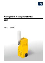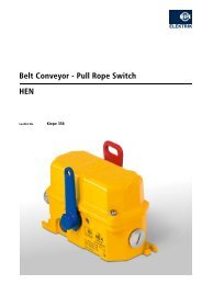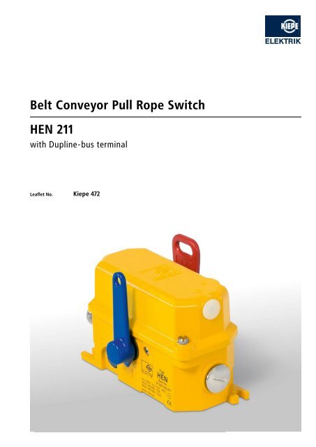
Belt Conveyor Pull Rope Switch HEN 211
Belt Conveyor Pull Rope Switch HEN 211
Belt Conveyor Pull Rope Switch HEN 211

Create successful ePaper yourself
Turn your PDF publications into a flip-book with our unique Google optimized e-Paper software.
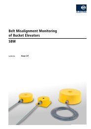
<strong>Belt</strong> conveyor pull rope switch<br />
hen <strong>211</strong><br />
with Dupline - bus terminal<br />
leaflet no. Kiepe 472
application<br />
Kiepe <strong>Pull</strong> <strong>Rope</strong> <strong>Switch</strong>es <strong>HEN</strong> provide a switching system<br />
to isolate the power to conveyor systems and other process<br />
equipment in event of an emergency. The devices have been<br />
designed for a maximum of safe operation under severe<br />
conditions.<br />
Kiepe <strong>Pull</strong> <strong>Rope</strong> <strong>Switch</strong>es and accessories meet the requirements<br />
of international safety standards with respect to personnel safety<br />
and equipment (BGI 710).<br />
operation<br />
Kiepe <strong>Pull</strong> <strong>Rope</strong> <strong>Switch</strong>es are actuated by a plastic coated steel<br />
wire rope placed along-side the conveyor. <strong>Pull</strong>ing on the rope<br />
at any point will trip and automatically lock the switches, deenergizing<br />
the conveyor starter contactor.<br />
Each switch is bi-directional in operation and has two ropes fitted<br />
to it from opposite directions terminating with a spring at the<br />
anchor points. The springs will operate the switch in the event of<br />
rope breakage. The length of rope in either direction may be up to<br />
50 meters. After tripping, the mechanical latch can be released only<br />
on the switch itself.<br />
monitoring<br />
In addition to the emergency cut-out function the <strong>HEN</strong> <strong>211</strong><br />
provides a Dupline field and installation bus node of the Carlo<br />
Gavazzi company. The Dupline system offers an economic solution<br />
to locate actuated pull rope switches within large conveying<br />
systems.<br />
Up to 128 independent signals can be transmitted via merely<br />
two wires of the Dupline bus towards any direction over several<br />
kilometres.<br />
The Dupline bus is a pure information bus and not a safety bus.<br />
<strong>Switch</strong>ing off a conveyor must be realized by disconnecting the<br />
safety circuit via positive making switching elements.<br />
To shorten installation work both circuits can be run in one cable.<br />
By means of a manual coder an address will be applied to each<br />
pull rope switch.<br />
The channel generator continously transmits the digital pulse<br />
code (the Dupline carrier signal) to the Dupline network. It<br />
synchronises the system via the clock pulse and time control<br />
of all bus participants connected to the system. It enables the<br />
connection to all important upper-level control systems, e.g.<br />
Profibus-DP, DeviceNet and others.<br />
technical data<br />
Device complies with EN 60947-5-1<br />
EN ISO 13850<br />
VDE 0110 - degree of pollution: 2 (interior), 4 (exterior)<br />
BGI 710 (UVV-VBG 10)<br />
Housing<br />
Aluminium GK-AlSi12<br />
Finish<br />
2-component DD-tile enamel<br />
Enclosure yellow, RAL 1004<br />
Actuating lever red, Ral 3000<br />
Reset lever blue, RAL 5010<br />
Mounting 2 bolts M 8<br />
Ambient temperature - 25 °C … + 70 °C<br />
Protection IP 67 according to EN 60529<br />
<strong>Switch</strong>ing system<br />
2 positive making NC - contacts for emergency cut off<br />
1 NO-contact to activate the bus module<br />
Rated insulation voltage U i<br />
AC 380 V<br />
Rated operational voltage U e<br />
AC 240 V<br />
Conventional thermal current I th<br />
16 A<br />
Breaking capacity I e / U e<br />
AC 10 A/230 V<br />
Connection max. 2,5 mm 2<br />
Cable entry 2 x M 25 x 1,5<br />
Bus terminal<br />
Operating voltage of the bus module<br />
via Dupline bus<br />
Order number 91.043 450.<strong>211</strong>
accessoires<br />
<strong>Pull</strong> rope, flexible steel wire, plastic coated, n 3 mm, red color,<br />
50 m length<br />
100 m length<br />
500 m length<br />
94.045 731.011<br />
94.045 731.021<br />
94.045 731.031<br />
Tension spring, stainless steel, 170 mm x n 20 mm 94.000 026.681<br />
Turnbuckle (metal, 1 hook, 1 eye) 215.22.80.02.01<br />
<strong>Rope</strong> clamp, egg-formed, size 3 94.047 869.001<br />
Eyebolt M 12 x 60 94.045 727.001<br />
Eyebolt M 12 x 200 94.045 727.002<br />
Swing hook M 10 94.045 728.001<br />
<strong>Switch</strong>ing element SN 4 220.03.01.01.01<br />
Bus module type G 88 10 22 01 367.07.01.04.01<br />
adjustment<br />
1. Install the pull rope on one side of the actuating lever<br />
according to the drawing below.<br />
2. Adjust the rope tension in such a way that the spring will<br />
properly operate the switch. Maximum extension of the spring<br />
is 500 mm. Now detach again the turnbuckle.<br />
3. Repeat procedure 1. and 2. on the other side.<br />
4. Attach both turnbuckles and operate the switch.<br />
5. The now movable actuating lever should be balanced in the<br />
mid position by means of the two turnbuckles.<br />
6. To limit the actuating distance of the pull rope and to avoid an<br />
inadmissible extension of the spring, a rope loop of approx. 40<br />
to 60 mm longer than the tensioned spring should be installed<br />
in a parallel position.<br />
7. Reset the switch. The system is now ready for operation.<br />
<strong>Pull</strong> rope<br />
Clamp Tension wire lock Release lever<br />
installation<br />
The switches are easily installed along the edge of the conveyor<br />
structure. The actuating lever should be positioned adjacent to<br />
the belt edge with the reset lever on the outside. Flexible vinyl<br />
coated steel wire is available for the pull rope. One egg-formed<br />
clamp is used for each rope fastening point.<br />
For guiding and rope support eyebolts are used at intervals up<br />
to 2,5 m. Stainless steel springs at the end of the rope ensure<br />
operation of the switch in the event of rope breakage (Fail safe).<br />
The spring pretension is adjusted by means of turnbuckles<br />
which can simply be attached onto the actuating lever. Since the<br />
switches are bi-directional in operation, variations of temperature<br />
which can influence the rope length become balanced by means<br />
of the two springs.<br />
installation<br />
Swing hook<br />
Tension<br />
spring<br />
Turnbuckle<br />
Turnbuckle<br />
Clamp<br />
Clamp<br />
Angle of<br />
Eyebolts<br />
actuating<br />
Eyebolts<br />
M 12 x 60 15° 15°<br />
M 12 x 60<br />
Swing hook<br />
Tension<br />
spring<br />
Actuating distance<br />
max. 0,3 m<br />
Actuating distance<br />
<strong>Rope</strong> loop max. 2,5 m<br />
<strong>Pull</strong> rope <strong>Pull</strong> rope<br />
max. 2,5 m<br />
<strong>Rope</strong> loop
dimensions<br />
Reset lever<br />
Dome light<br />
(optional)<br />
Angle of actuating<br />
15°<br />
15°<br />
192<br />
176<br />
162<br />
80,5<br />
54<br />
15<br />
8,5<br />
7<br />
31<br />
123<br />
16<br />
7<br />
43 80<br />
Plug M 25 x 1,5<br />
Cable entry M 25 x 1,5<br />
22<br />
13,25<br />
81<br />
119<br />
Actuating lever<br />
contact arrangements<br />
13 14 21<br />
N.O.<br />
41<br />
N.C.<br />
22<br />
42<br />
G 88 10 22 01<br />
D+ D+ D– D–<br />
Subjects to change without notice.<br />
Vossloh Kiepe GmbH<br />
D-40599 Düsseldorf (Germany) · Kiepe-Platz 1<br />
Phone +49 (0) <strong>211</strong> 74 97-0 · Fax +49 (0) <strong>211</strong> 74 97-420<br />
info@kiepe-elektrik.com · www.kiepe-elektrik.com<br />
472/2–04/09