Conveyor Belt-misalignment Switch SEL
Conveyor Belt-misalignment Switch SEL
Conveyor Belt-misalignment Switch SEL
- No tags were found...

Create successful ePaper yourself
Turn your PDF publications into a flip-book with our unique Google optimized e-Paper software.
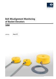
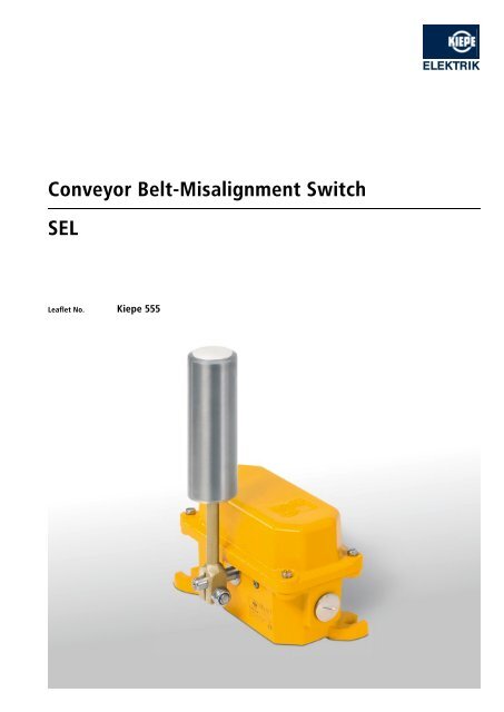
<strong>Conveyor</strong> <strong>Belt</strong>-<strong>misalignment</strong> <strong>Switch</strong><strong>SEL</strong>Leaflet No. Kiepe 555
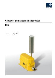
APPLICATIONKIEPE belt <strong>misalignment</strong> switches of the <strong>SEL</strong> type are designed forheavy duty application and used at fixed belt conveyors accordingto DIN EN 620 requirements in order to keep the risk of unintentionaloperation as low as possible. The lateral movement of theconveyor belt is monitored and by switching off the conveyor inthe case of unacceptable belt drift, the belt monitoring preventsdamage and destruction of the belt and the machine.Misalignment <strong>Switch</strong>es are allocated in pairs on both sides at thecarrying belt and return belt. The total number of pairs to be usedand their installation points are dependent on design characteristicssuch as e.g. horizontal or vertical tensioning stations, singleendedor reversible operation and the length of the belt conveyor.Usually (horizontal tensioning station, single-ended operation,length of up to 30 m) one pair of switches is installed in front ofthe discharge station at the carrying belt.OPERATIONInadmissible belt drift occurs when the belt edge approaches theend of the supporting rollers through lateral movement and surpassesit. Then the actuator of the <strong>misalignment</strong> switch is operatedand displaced. In the case of a displacement of the actuator, thefirst adjustable switching point is between 5° and 15°, the secondbetween 15° and 35°. The shut-off of the conveyor is carried outoptionally with the first or second switching point.Alternatively, a <strong>misalignment</strong> warning can be created with the firstswitching point or a safety switch-off with the second switchingpoint. The actuating roller is equipped with ball-bearings andmade of alloyed steel. With its large roll diameter of 48 mm it is resistantto wear and used for belt speeds of up to 3 m/s and higher.TECHNICAL DATAComplies with EN 60947-5-1Suited for controls and facilities according to EN 60204EnclosureCast iron, EN-GJL-200Finish 2 component DD-tile enamel, yellow RAL 1004Mounting2 oblong holes for M10 screwsAdmissible ambient temperature–25°C … +70°CProtection IP 67 according to EN 60529<strong>Switch</strong>ing system2 cam operated snap action change over contacts SPDT, positive makingActuator<strong>SEL</strong> 011: Roller lever, Ø48 mm, stainless steel<strong>SEL</strong> 311: Roller lever, Ø108 mm, stainless steel<strong>Switch</strong>ing points Adjustable between 5° … 15° or 15° … 35° (standard setting is 2 x 10°)Displacement of actuator max. 75°Rated operating voltage U eAC 230 V, DC 230 VConventional thermal current I th6 ABreaking capacityAC-15DC-24U e = AC 240V, I e = 1.5AT = 2 .. 3 ms, max. 3 ACable entry Threaded hole 2 x M 25 x 1.51x screwed cable gland M 25 x 1.5; sealing area Ø11mm to Ø16mm1x dummy plug M 25 x 1.5Connection cross section max. 1.5 mm 2Protective conductor connection Inside enclosure, M 4, max. 2.5 mm 2Contact life0.5 x 10 6 switching cycles at 100 % I eMechanical life10 4 switching cyclesOptionalVentilation duct to avoid condensationPlease note: The switches may be used in control circuits only!
<strong>SEL</strong>ECTION TABLETypeContactconfigurationChange over contacts (SPDT)Order number<strong>SEL</strong> 011 2 92.056 979.011<strong>SEL</strong> 311 2 91.056 979.311Spares and optionsActuating roller, stainless steel, ∅ 48 mm 93.058 650.001Actuating roller, stainless steel, ∅ 108 mm 92.043 542.001<strong>Switch</strong> element 220.06.04.01.05Ventilation duct 580.00.16.01.01CONNECTION DIAGRAM<strong>Switch</strong>ing elements according to DIN EN 50013242221141211Actuator sideDimensions <strong>SEL</strong> 011119.57029112412 M25 x 1.5Cable entry∅ 4811177205M25 x 1.5Cable entry
Dimensions <strong>SEL</strong> 31112∅ 1082051771112M25 x 1.5124M25 x 1.52651771135370205Subject to change without notice.Vossloh Kiepe GmbHD-40599 Düsseldorf (Germany) · Kiepe-Platz 1Telephone +49(0)211 7497-0 · Fax +49(0)2117497-420info@kiepe-elektrik.com · www.kiepe-elektrik.com555/2–02/09