Belt Conveyor - Pull Rope Switch HEN
Belt Conveyor - Pull Rope Switch HEN
Belt Conveyor - Pull Rope Switch HEN

Create successful ePaper yourself
Turn your PDF publications into a flip-book with our unique Google optimized e-Paper software.
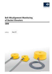
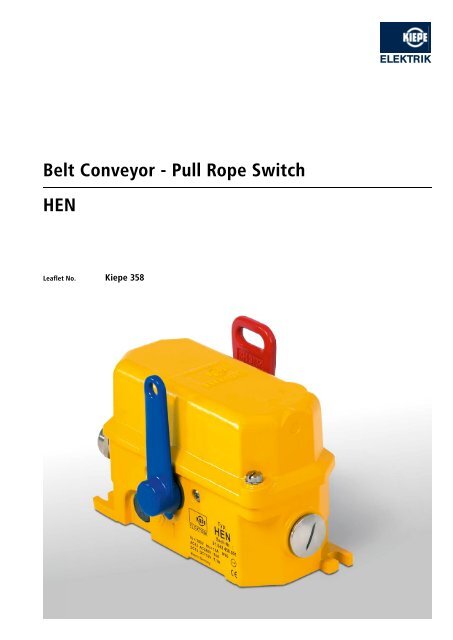
<strong>Belt</strong> <strong>Conveyor</strong> - <strong>Pull</strong> <strong>Rope</strong> <strong>Switch</strong><strong>HEN</strong>Leaflet No. Kiepe 358
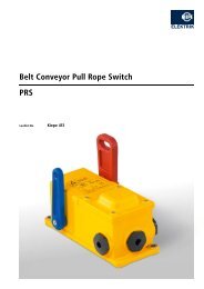
APPLICATIONKiepe pull rope emergency stop switches are used according to DINEN 620 requirements together with functionally suited accessories,largely consisting of pull rope, tension springs and eyebolts, forthe assembly of emergency stop systems at fixed belt conveyors.These emergency stop systems meet the requirements of internationalsafety standards to ensure safety at work and to preventdamage and destruction of the machine (BGI 710).OPERATIONThe emergency stop function is implemented with positive makingnormally closed contacts according to the closed circuit principle.The direct operating switching mechanism inside the switch is ofsnap action and is actuated when the pull rope is either pulledin any direction or if the rope breaks. After the triggering of theemergency stop function, the switching mechanism locks in the offposition. Through manual actuation of the blue reset lever locallyat the pull rope switch the switching mechanism is reset to theoperating position and the belt conveyor is prepared for start-up.The resetting of the switching mechanism may not start the beltconveyor.With the <strong>HEN</strong> type pull rope switch, the pull rope is symmetricallytensioned on both sides of the red release lever and thus acomplete compensation of the rope forces at the release leveris achieved. For this reason, double-sided pull rope switches ofthe <strong>HEN</strong> design are especially suitable for outdoor use with largechanges of the ambient temperature (summer – winter) of up to60°C and more.TECHNICAL DATAComplies with EN 620, BGI 710 (UVV-VGB 10)DIN EN ISO 13850, EN 60947-5-5, EN 60947-5-1Suited for controls and facilities according to EN 60204Enclosure Aluminum alloy GK-AlSi 12Finish 2 component DD-tile enamel, yellow, RAL 1004Actuating lever, red, RAL 3000Reset lever, blue, RAL 5010Mounting2 oblong holes for M8 screwsAdmissible ambient temperature - 25 °C ... + 70 °CExtended temperature range- 40 °C ... + 70 °C for <strong>HEN</strong> 70x modelsProtection IP 67 according to EN 60529<strong>Switch</strong>ing systemmax. 3NC and 3NO cam operated switches, positive making,snap actionRated operating voltage U eAC 240 V, DC 250 VConventional thermal current I th16 ABreaking capacityAC-15DC-13U e = 230 V, I e = 6 AU e = 110 V, I e = 1.1 ACable entry Threaded holes, 2 x M25 x 1.51 x screwed cable gland M25 x 1.5; sealing area Ø 11mm to Ø 16mm1 x dummy plug M25 x 1.5Connection cross section max. 2,5 mm 2Protective conductor connection Inside enclosure, M4, max. 2.5 mm 2Contact life0.5 x 106 switching cycles at 100 % I eMechanical life10 4 switching cyclesOptionalVentilation duct to avoid condensationGold-plated contactsDome lightPlease note: The switches may be used in control circuits only!
CONNECTION DIAGRAM<strong>Switch</strong>ing elements according to DIN EN 50013(the maximum configuration with 3NO / 3NC is shown)131421223334414253546162DIMENSIONS15°15°123X1X2317119.543 801619217616280.55413.2515228.581119Subject to change without notice.Vossloh Kiepe GmbHD-40599 Düsseldorf (Germany) · Kiepe-Platz 1Telephone +49 (0) 211 74 97-0 · Fax +49 (0) 211 74 97-420info@kiepe-elektrik.com · www.kiepe-elektrik.com358/2–02/09