Misalignment Switch SBW
Misalignment Switch SBW
Misalignment Switch SBW

Create successful ePaper yourself
Turn your PDF publications into a flip-book with our unique Google optimized e-Paper software.
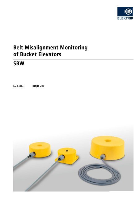
elt misalignment monitoringof bucket elevatorssbWleaflet no. Kiepe 217
applicationKiepe Belt <strong>Misalignment</strong> <strong>Switch</strong>es <strong>SBW</strong> are used in bucklet elevatorinstallations for monitoring the true tracking of the elevatorsbelt. The switches will operate if the belt exceeds the permissibledeviation from the nominal tracking. The switch´s output signalenergizes the connected control units to stop the elevator inorder to avoid spillage of material, severe damage and seriousdowntime.OperationThe monitoring of the true tracking of the buckets is realized bymounting a pair of inductive proximity switches near theheadpulley on the carrying side and another pair located nearthe tailpulley on the return side. <strong>Misalignment</strong> of the bucketsbecomes detected as soon as a bucket mistracks into the sensingzone of the proximity switch.The sensing distance of the inductive proximity switches isadjustable by means of a potentiometer accessible from thesensor´s surface. A LED indicates when the sensor´s oscillatorfield is interfered by a bucket. All switches can be programmedfrom NO to NC.technical dataDevice complies with IEC 947-1EN 50081-1EN 50082-2MountingNon-f lush mountingOperating voltageDC-Version: 15 … 60 VAC-Version: 20 … 250 VLoad current400 mASurge current4 A (AC- type)Minimum load current8 mA (AC- type)Hysteresis~ 10 % s nAmbient temperature - 20 °C … + 70 °CProtection IP 67<strong>Switch</strong>ing frequencyAC: 25 Hz, DC: 100 HzConnecting cableDC: 3 x 0.50 mm 2 , length: approx. 2 mAC: 2 x 0.75 mm 2 , length: approx. 2 mOutput c ircuitDC - PNP - NC / NO - programmableAC - NC / NO - programmableselection tableType s n (mm) AdjustablerangeDC AC Min. diameterof the holeOrder Number<strong>SBW</strong> 001 55 10 … 80 mm x 160 mm ∅ 94.046 510.001<strong>SBW</strong> 051 55 10 … 80 mm x 160 mm ∅ 94.046 510.051Mounting plate required for type <strong>SBW</strong> 001 / 051 96.048 808.001<strong>SBW</strong> 002 70 10 … 110 mm x 250 mm ∅ 94.046 510.002<strong>SBW</strong> 052 70 10 … 110 mm x 250 mm ∅ 94.046 510.052Mounting plate for type <strong>SBW</strong> 002 / 052, complete with plastic rear cover 96.048 808.002<strong>SBW</strong> 003 120 20 … 150 mm x 400 mm ∅ 94.046 510.003<strong>SBW</strong> 053 120 20 … 150 mm x 400 mm ∅ 94.046 510.053Mounting plate for type <strong>SBW</strong> 003 / 053, complete with plastic rear cover 96.048 808.003s n (mm) = Rated operating distance, related to steel ST 37. For other metals a reduction factor must be considered:V 4 A: s n x 0,65 - Al: s n x 0,4 - Cu: s n x 0,45 - Ms: s n x 0,6Note: The switches types <strong>SBW</strong> 002 / 052 and <strong>SBW</strong> 003 / 053 may become operated by means of movable metal parts inf luencing theswitch from the side or from the back. To avoid this fault operation we recommend to protect the switch with a plastic cover.
operating modes<strong>Switch</strong>es in AC-Mode to fit in relay/contactor-circuitsUp to 4 switches can operate in series when using the NC-mode.The voltage drop of each switch amounts to 6 volts.<strong>Switch</strong>es in DC-Mode -protected against short- circuits and wrong polarityUp to 4 switches can operate as well in series when using the NCmodeas in parallel when using the NO-mode. <strong>Switch</strong>es inDC-mode are suitable to fit directly a PLC.NONCAll switches are NO -Preset by factory. To select the NC -modeloose the cable gland and remove the connecting cable. Now theslide switch (see drawing beside) can be moved to the NC -position.slide switchNote:Exceeding the nominal operating distance s n will cause an increaseof the switching hysteresis and of the sensi tivity against metal partsapproaching from the back or from the side.installationThe assembly consists of the inductive proximity switches, theconnecting cable and a flame resistant mounting plate, togetherwith a gasket, a plastic rear cover and a set of fixing screws.A hole must be cut in both sides of the chute wall of the bucketelevator. The holes at the headpulley as well as those at thetailpulley should be cut in the travel line of the buckets.Since the switches are designed for a non-flush mounting a metalfreearea should be considered around the switch (please refer tothe selection table: min. diam.).The mounting plates with their gaskets shall be placed on theopenings in such a way that they fully cover and seal the holes.The mounting plates are fixed by means of the supplied screws.For further information please refer to the mounting instructions.Chute wallBeltBucketBucketMetal-free area<strong>Misalignment</strong> switchBucketMounting plate
dimensions<strong>SBW</strong> 001/ 05118521018555Opening diameter ∅ 1604085,58065725 22210movable444PotentiometerLED<strong>SBW</strong> 002 / 0523002757ca. 82ca. 8203002754028Opening diameter ∅ 250∅ 13∅ 100movablePotentiometerLEDCover not shown<strong>SBW</strong> 003 / 0534504261427145ca. 1060∅ 3035∅ 13450426142Opening diameter ∅ 400ca. ∅ 260∅ 160PotentiometerLEDmovableCover not shownSubject to change without notice.Vossloh Kiepe GmbHD-40599 Düsseldorf (Germany) · Kiepe-Platz 1Phone +49 (0) 211 74 97-0 · Fax +49 (0) 211 74 97-420info@kiepe-elektrik.com · www.kiepe-elektrik.com217/2–04/09