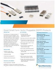
Power Connector Systems
Power Connector Systems
Power Connector Systems

You also want an ePaper? Increase the reach of your titles
YUMPU automatically turns print PDFs into web optimized ePapers that Google loves.
<strong>Power</strong> <strong>Connector</strong>s & Interconnection <strong>Systems</strong><br />
Mini CROWN EDGE High Current <strong>Power</strong> <strong>Connector</strong>s<br />
for 1U/2U Pluggable VRMs (Continued)<br />
Cutout View Showing<br />
CROWN BAND <strong>Power</strong> Contacts<br />
Flexible <strong>Power</strong> Arrangements<br />
In contrast with other VRM interconnects where U-shaped<br />
contacts are used, in Mini CROWN EDGE connectors all<br />
power contacts are isolated from each other, allowing the<br />
design engineer flexibility in laying out multiple voltage<br />
rails and returns.<br />
Robust, Low-Profile Housing Design<br />
Mini CROWN EDGE connectors feature a low profile housing<br />
design that leaves more room for placement of components<br />
on the VRM board. Rigorous shock and vibration<br />
testing shows that the two latches used to hold the VRM<br />
are robust enough to safely hold 2U height modules.<br />
Voltage Regulation Module<br />
(VRM) <strong>Connector</strong>s<br />
Current Ratings<br />
As shown on the chart at<br />
right, Mini CROWN EDGE<br />
power contacts are rated at<br />
25A at 30°C temperature<br />
rise.<br />
160<br />
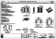
Product Specifications<br />
Materials<br />
Insulators<br />
Contacts<br />
Finishes<br />
Contacts<br />
Electrical<br />
High Temperature Thermoplastic, UL 94V-0 flammability rated, color black<br />
Copper Alloy<br />
Selectively plated gold (30 micro inches minimum) with tin on<br />
terminations, all over nickel<br />
Current Rating UL 30 Amp, per UL 1977, para 16<br />
<strong>Power</strong> Contacts CUR/CSA 25 Amp<br />
Signal Contacts<br />
UL 3 Amp, per UL 1977, para 16<br />
CUR/CSA<br />
2 Amp<br />
Contact resistance<br />
<strong>Power</strong><br />
2 MΩ maximum initial, (3 MΩ maximum<br />
after 250 cycles durability), at 25A<br />
Signal<br />
10 MΩ maximum initial, (15 MΩ maximum<br />
after 250 cycles durability)<br />
Dielectric Strength 1,500 VDC for 1 minute, per UL 1977, para 17.3b<br />
Mechanical<br />
Durability<br />
Shock<br />
Vibration<br />
Operating Temperature<br />
Temperature Life<br />
Recommended PCB Hole,<br />
Compliant Press-Fit and<br />
Solder tail<br />
Marking<br />
250 Cycles, per EIA-364-9C<br />
per EIA-364-27B, Test Condition H<br />
per EIA-364-28D, Test Condition VII<br />
-40° to +105°C<br />
105°C for 96 hours, per EIA-364-17B, Method C<br />
Finished hole: 0.040 +/- .0030″ dia. (1.02 +/- .08 mm dia.)<br />
Drilled hole: 0.0453 +/- .0005″ dia. (1.15 =/- .013 mm dia.)<br />
Copper Plate: 0.0010″ (.025 mm) min. per surface<br />
Tin Plate: 0.0003″ (.008 mm) min. per surface<br />
<strong>Connector</strong>s are marked with manufacturer’s logo, part number and lot code<br />
Catalog 1773096 Dimensions are in inches and Dimensions are shown for USA: 1-800-522-6752 South America: 55-11-2103-6000<br />
Revised 7-07 millimeters unless otherwise reference purposes only. Canada: 1-905-470-4425 Hong Kong: 852-2735-1628<br />
specified. Values in brackets Specifications subject Mexico: 01-800-733-8926 Japan: 81-44-844-8013<br />
www.tycoelectronics.com are metric equivalents. to change. C. America: 52-55-1106-0803 UK: +44 (0) 800-267-666