Lumax Family of ICDs and CRTâDs - BIOTRONIK USA - News
Lumax Family of ICDs and CRTâDs - BIOTRONIK USA - News
Lumax Family of ICDs and CRTâDs - BIOTRONIK USA - News

Create successful ePaper yourself
Turn your PDF publications into a flip-book with our unique Google optimized e-Paper software.
<strong>BIOTRONIK</strong><br />
<strong>Lumax</strong> <strong>ICDs</strong> <strong>and</strong> CRT‐Ds<br />
Technical Manual<br />
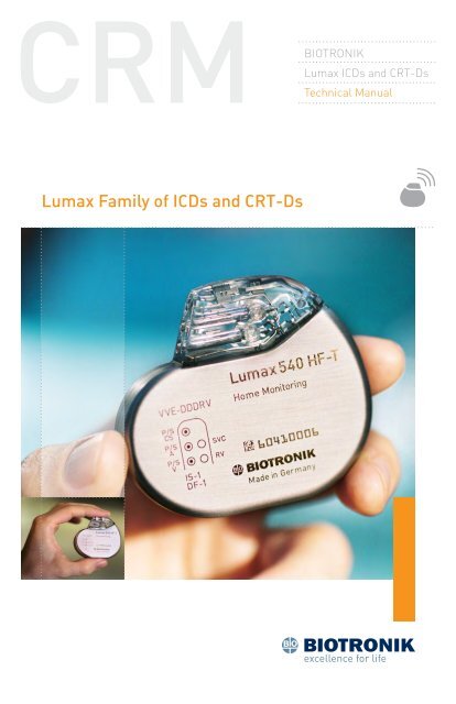
<strong>Lumax</strong> <strong>Family</strong> <strong>of</strong> <strong>ICDs</strong> <strong>and</strong> CRT‐Ds
X‐ray Identification<br />
<strong>Lumax</strong> <strong>Family</strong><br />
Implantable Cardioverter Defibrillator <strong>and</strong> Cardiac Resynchronization<br />
Therapy Defibrillators<br />
Inside the housing:<br />
Model X‐Ray Identification Year <strong>of</strong> Manufacture<br />
<strong>Lumax</strong> 300 HR nn<br />
<strong>Lumax</strong> 340 HR nn<br />
<strong>Lumax</strong> 500 SH nn<br />
<strong>Lumax</strong> 540 SH nn<br />
Caution<br />
Federal (U.S.A.) law restricts this device to sale by, or on the order <strong>of</strong>,<br />
a physician.<br />
©2010 <strong>BIOTRONIK</strong>, Inc., all rights reserved.
Contents<br />
<strong>Lumax</strong> <strong>Family</strong> Technical Manual i<br />
1. General.............................................................................................. 1<br />
1.1 System Description...........................................................................1<br />
1.2 Indications <strong>and</strong> Usage.......................................................................3<br />
1.3 Contraindications..............................................................................4<br />
1.4 Warnings <strong>and</strong> Precautions................................................................4<br />
1.4.1 Sterilization, Storage, <strong>and</strong> H<strong>and</strong>ling............................................6<br />
1.4.2 Device Implantation <strong>and</strong> Programming.......................................7<br />
1.4.3 Lead Evaluation <strong>and</strong> Connection..................................................9<br />
1.4.4 Follow‐up Testing.......................................................................10<br />
1.4.5 Pulse Generator Explant <strong>and</strong> Disposal......................................10<br />
1.4.6 Hospital <strong>and</strong> Medical Hazards....................................................11<br />
1.4.7 Home <strong>and</strong> Occupational Hazards...............................................12<br />
1.4.8 Cellular Phones..........................................................................12<br />
1.4.9 Electronic Article Surveillance (EAS).........................................13<br />
1.4.10 Home Appliances......................................................................13<br />
1.4.11 Home Monitoring .....................................................................14<br />
1.5 Potential/Observed Effects <strong>of</strong> the Device on Health.......................15<br />
1.5.1 Potential Adverse Events...........................................................15<br />
1.5.2 Observed Adverse Events...........................................................16<br />
1.6 Clinical Studies...............................................................................25<br />
1.6.1 Kronos LV‐T Study......................................................................25<br />
1.6.2 Tupos LV⁄ATx Study.....................................................................27<br />
1.6.3 <strong>Lumax</strong> HF‐T V‐V Clinical Study..................................................44<br />
1.6.4 TRUST Clinical Study..................................................................51<br />
1.6.5 Deikos A+ ...................................................................................58<br />
1.7 Patient Selection <strong>and</strong> Treatment....................................................61<br />
1.7.1 Individualization <strong>of</strong> Treatment....................................................61<br />
1.7.2 Specific Patient Populations......................................................62<br />
1.8 Patient Counseling Information......................................................63<br />
1.9 Evaluating Prospective CRT‐D/ICD Patients..................................63<br />
2. Device Features............................................................................... 65<br />
2.1 Cardiac Resynchronization Therapy (CRT).....................................65<br />
2.2 Sensing (Automatic Sensitivity Control).........................................69<br />
2.2.1 Right Ventricular Sensitivity Settings........................................69<br />
2.2.2 Minimum Right Ventricular Threshold......................................71
ii <strong>Lumax</strong> <strong>Family</strong> Technical Manual<br />
2.2.3 Atrial Sensitivity Settings...........................................................71<br />
2.2.4 Minimum Atrial Threshold.........................................................72<br />
2.2.5 Left Ventricular Sensitivity Settings...........................................72<br />
2.2.6 Minimum Left Ventricular Threshold.........................................73<br />
2.2.7 Far Field Protection....................................................................73<br />
2.2.8 Additional Sensing Parameters.................................................73<br />
2.3 Automatic Threshold Measurement (ATM).....................................74<br />
2.3.1 Signal Quality Check...................................................................75<br />
2.3.2 Threshold Measurement............................................................75<br />
2.3.3 Loss <strong>of</strong> Capture Detection..........................................................76<br />
2.3.4 ATM in <strong>Lumax</strong> HF‐T Models.......................................................76<br />
2.4 Ventricular Tachyarrhythmia Detection..........................................76<br />
2.4.1 VF Classifications.......................................................................77<br />
2.4.2 VT Interval Counters...................................................................77<br />
2.4.3 VT Classification.........................................................................77<br />
2.4.4 SMART Detection........................................................................78<br />
2.4.5 Onset ..........................................................................................78<br />
2.4.6 Stability.......................................................................................79<br />
2.4.7 Sustained VT Timer....................................................................79<br />
2.4.8 VT Monitoring Zone....................................................................80<br />
2.4.9 Atrial Monitoring Zone...............................................................80<br />
2.5 Tachyarrhythmia Redetection.........................................................80<br />
2.5.1 VT Redetection............................................................................80<br />
2.5.2 SMART Redetection....................................................................81<br />
2.5.3 Forced Termination....................................................................81<br />
2.5.4 VF Redetection............................................................................81<br />
2.6 Tachyarrhythmia Termination.........................................................81<br />
2.7 Tachyarrhythmia Therapy...............................................................81<br />
2.7.1 Therapy Options..........................................................................81<br />
2.7.2 Anti‐Tachycardia Pacing (ATP)...................................................82<br />
2.7.3 Shock Therapy............................................................................84<br />
2.7.4 Progressive Course <strong>of</strong> Therapy..................................................90<br />
2.8 Bradycardia Therapy.......................................................................91<br />
2.8.1 Bradycardia Pacing Modes.........................................................91<br />
2.8.2 Basic Rate...................................................................................92<br />
2.8.3 Night Rate...................................................................................92<br />
2.8.4 Rate Hysteresis...........................................................................92
<strong>Lumax</strong> <strong>Family</strong> Technical Manual iii<br />
2.8.5 Dynamic AV Delay.......................................................................95<br />
2.8.6 IOPT............................................................................................97<br />
2.8.7 Upper Tracking Rate...................................................................98<br />
2.8.8 Mode Switching..........................................................................99<br />
2.8.9 PMT Management....................................................................100<br />
2.8.10 VES Discrimination after Atrial Sensed Events.....................103<br />
2.8.11 Rate‐Adaptive Pacing.............................................................103<br />
2.8.12 Pulse Amplitude.....................................................................104<br />
2.8.13 Pulse Width.............................................................................104<br />
2.8.14 Post Ventricular Atrial Refractory Period..............................105<br />
2.8.15 PVARP after VES.....................................................................105<br />
2.8.16 Auto PVARP............................................................................105<br />
2.8.17 Noise Response......................................................................105<br />
2.8.18 Post Shock Pacing..................................................................105<br />
2.9 EP Test Functions..........................................................................106<br />
2.9.1 P <strong>and</strong> R‐wave Amplitude Measurements................................106<br />
2.9.2 Pacing Impedance Measurements...........................................107<br />
2.9.3 Shock Impedance Measurements............................................107<br />
2.9.4 Testing for Retrograde Conduction..........................................107<br />
2.9.5 Pacing Threshold .....................................................................108<br />
2.9.6 Arrhythmia Induction Features................................................108<br />
2.9.7 Manual Shock...........................................................................109<br />
2.9.8 Test Shock................................................................................109<br />
2.9.9 Manual ATP...............................................................................110<br />
2.9.10 Emergency Shock...................................................................110<br />
2.10 Special Features..........................................................................110<br />
2.10.1 ICD Therapy Status.................................................................111<br />
2.10.2 Home Monitoring ...................................................................111<br />
2.10.3 Real‐time IEGM Transmission ..............................................121<br />
2.10.4 Capacitor Reforming..............................................................121<br />
2.10.5 Patient <strong>and</strong> Implant Data.......................................................122<br />
2.10.6 System Status.........................................................................122<br />
2.10.7 HF Monitor Statistics..............................................................123<br />
2.10.8 Holter Memory........................................................................124<br />
2.10.9 Timing Statistics.....................................................................126<br />
2.10.10 Atrial Arrhythmias................................................................127<br />
2.10.11 Ventricular Arrhythmias.......................................................127
iv <strong>Lumax</strong> <strong>Family</strong> Technical Manual<br />
2.10.12 Sensor...................................................................................127<br />
2.10.13 Sensing.................................................................................128<br />
2.10.14 Impedances..........................................................................128<br />
2.10.15 Automatic Threshold ...........................................................128<br />
3. Sterilization <strong>and</strong> Storage................................................................129<br />
4. Implant Procedure..........................................................................131<br />
4.1 Implant Preparation......................................................................131<br />
4.2 Lead System Evaluation................................................................134<br />
4.3 Opening the Sterile Container......................................................135<br />
4.4 Pocket Preparation.......................................................................136<br />
4.5 Lead to Device Connection............................................................136<br />
4.6 Blind Plug Connection..................................................................139<br />
4.7 Program the ICD⁄CRT‐D................................................................140<br />
4.8 Implant the ICD⁄CRT‐D..................................................................140<br />
5. Follow‐up Procedures.....................................................................145<br />
5.1 General Considerations................................................................145<br />
5.2 Longevity ......................................................................................145<br />
5.2.1 <strong>Lumax</strong> 300/340 Devices............................................................146<br />
5.2.2 <strong>Lumax</strong> 500/540 Devices............................................................148<br />
5.3 Explantation..................................................................................151<br />
6. Technical Specifications..................................................................153<br />
Appendix A...........................................................................................163<br />
Appendix B – Known Anomalies..........................................................165
<strong>Lumax</strong> <strong>Family</strong> Technical Manual v<br />
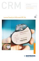
VR (‐T) DR (‐T)/VR-T DX HF (‐T)<br />
Figure 1: <strong>Lumax</strong> <strong>ICDs</strong> <strong>and</strong> CRT‐D<br />
Table 1: <strong>Lumax</strong> Specifications<br />
Battery Voltage<br />
3.2 Volts<br />
Maximum Shock Energy<br />
300⁄500 Models 30 Joules programmed<br />
340⁄540 Models 40 Joules programmed<br />
Defibrillation Lead Ports<br />
Two DF1 (3.2 mm)<br />
Pacing Lead Ports<br />
VR(‐T) Models<br />
One IS‐1 (3.2 mm)<br />
DR(‐T)/VR-T DX Models<br />
Two IS‐1 (3.2 mm)<br />
HF(‐T) Models<br />
Three IS‐1 (3.2 mm)<br />
Materials<br />
Housing<br />
Titanium<br />
Header<br />
Epoxy Resin<br />
Sealing Plug<br />
Silicone<br />
Detailed technical specifications are provided in Section 6.
vi <strong>Lumax</strong> <strong>Family</strong> Technical Manual
<strong>Lumax</strong> <strong>Family</strong> Technical Manual 1<br />
1. General<br />
1.1 System Description<br />
The <strong>Lumax</strong> family <strong>of</strong> Implantable Cardioverter Defibrillators (<strong>ICDs</strong>) <strong>and</strong><br />
Cardiac Resynchronization Therapy Defibrillators (CRT‐Ds) detect <strong>and</strong><br />
treat ventricular tachyarrhythmias <strong>and</strong> provide rate adaptive bradycardia<br />
pacing support. The HF <strong>and</strong> HF‐T versions <strong>of</strong> <strong>Lumax</strong> provide Cardiac<br />
Resynchronization Therapy (CRT) through biventricular pacing. Both<br />
CRT‐Ds <strong>and</strong> <strong>ICDs</strong> detect <strong>and</strong> treat ventricular tachyarrhythmias <strong>and</strong><br />
provide rate adaptive bradycardia pacing support. They are designed to<br />
collect diagnostic data to aid the physician’s assessment <strong>of</strong> a patient’s<br />
condition <strong>and</strong> the performance <strong>of</strong> the implanted device.<br />
The <strong>Lumax</strong> family <strong>of</strong> devices provides therapy for ventricular<br />
tachyarrhythmias with a sophisticated range <strong>of</strong> programmable<br />
anti‐tachycardia pacing (ATP), <strong>and</strong>⁄or defibrillation therapy features. The<br />
shock polarity <strong>and</strong> energy may be programmed to tailor the therapy to<br />
appropriately treat each patient’s tachyarrhythmias. The <strong>ICDs</strong>⁄CRT‐Ds<br />
provide shock therapies with programmable energies from 5 to 40 joules.<br />
The <strong>Lumax</strong> family <strong>of</strong> <strong>ICDs</strong>⁄CRT‐Ds includes the following members:<br />
• <strong>Lumax</strong> HF—provides three chamber rate‐adaptive bradycardia<br />
pacing support including biventricular pacing via a left ventricular<br />
pacing lead. The CRT‐D uses right atrial <strong>and</strong> ventricular<br />
sensing⁄pacing leads to provide enhanced atrial <strong>and</strong> ventricular<br />
tachyarrhythmia discrimination through <strong>BIOTRONIK</strong>’s SMART<br />
Detection algorithm.<br />
• <strong>Lumax</strong> HF‐T—In addition to the functionality found with HF model,<br />
<strong>Lumax</strong> HF‐T also has <strong>BIOTRONIK</strong>’s Home Monitoring® System.<br />
The Home Monitoring System enables automatic exchange <strong>of</strong><br />
information about a patient’s cardiac status from the implant to the<br />
physician remotely.<br />
• <strong>Lumax</strong> DR—provides dual chamber rate adaptive bradycardia<br />
pacing support. The ICD uses atrial <strong>and</strong> ventricular sensing⁄pacing<br />
leads to provide enhanced atrial <strong>and</strong> ventricular tachyarrhythmia<br />
discrimination through <strong>BIOTRONIK</strong>’s SMART Detection algorithm.<br />
• <strong>Lumax</strong> DR‐T—In addition to the functionality found with the<br />
DR model, it also has <strong>BIOTRONIK</strong>’s Home Monitoring System.<br />
The Home Monitoring System enables automatic exchange <strong>of</strong><br />
information about a patient’s cardiac status from the implant to the<br />
physician remotely.
2 <strong>Lumax</strong> <strong>Family</strong> Technical Manual<br />
• <strong>Lumax</strong> VR—provides single chamber rate adaptive bradycardia<br />
pacing support as well as tachyarrhythmia detection <strong>and</strong> therapy.<br />
• <strong>Lumax</strong> VR‐T—In addition to the functionality found with st<strong>and</strong>ard<br />
VR model, it also has <strong>BIOTRONIK</strong>’s Home Monitoring System.<br />
The Home Monitoring System enables automatic exchange <strong>of</strong><br />
information about a patient’s cardiac status from the implant to the<br />
physician remotely.<br />
• <strong>Lumax</strong> VR-T DX – provides ventricular rate adaptive bradycardia<br />
pacing support that can include atrial tracking with a single pass<br />
ICD lead <strong>and</strong> also has <strong>BIOTRONIK</strong>’s Home Monitoring system.<br />
The 300⁄500 <strong>and</strong> 340⁄540 designation for each <strong>of</strong> the above‐described<br />
models denote the maximum programmable shock energy <strong>of</strong> 30 joules<br />
<strong>and</strong> 40 joules, respectively.<br />
The <strong>Lumax</strong> 500⁄540 models also feature a third programmable shock<br />
path for delivery <strong>of</strong> defibrillation⁄cardioversion shocks. The shock path<br />
is programmable between the different shock coils (SVC⁄RV) <strong>and</strong>⁄or the<br />
device housing. Section 2.7.3.6 provides further details on the available<br />
shock configurations.<br />
Additionally, the <strong>Lumax</strong> 500⁄540 models feature Automatic Threshold<br />
Measurement (ATM) <strong>of</strong> ventricular pacing thresholds. This feature<br />
is separately programmable for the right (RV) <strong>and</strong> left (LV) ventricle.<br />
Section 2.3 provides further details.<br />
The <strong>Lumax</strong> HF (‐T) models have three IS‐1 pacing⁄sensing header ports<br />
<strong>and</strong> two DF‐1 defibrillation⁄cardioversion ports. The <strong>Lumax</strong> DR (‐T)<br />
models have two IS‐1 pacing⁄sensing header ports. The <strong>Lumax</strong> VR (‐T)<br />
models have one IS‐1 pacing⁄sensing header ports. IS‐1 refers to the<br />
international st<strong>and</strong>ard whereby leads <strong>and</strong> generators from different<br />
manufacturers are assured a basic fit [Reference ISO 5841‐3:1992].<br />
DF‐1 refers to the international st<strong>and</strong>ard for defibrillation lead<br />
connectors [Reference ISO 11318:1993].<br />
External devices that interact with <strong>and</strong> test the implantable devices are<br />
also part <strong>of</strong> the ICD⁄CRT‐D System. These external devices include the<br />
ICS 3000 Programming <strong>and</strong> Tachyarrhythmia Monitoring System <strong>and</strong><br />
the Implant Module System Analyzer or Pacing System Analyzer for<br />
acute lead testing. The ICS 3000 programmer is used to interrogate <strong>and</strong><br />
program the ICD⁄CRT‐Ds.<br />
<strong>BIOTRONIK</strong> conducted the TRUST study to evaluate the safety <strong>and</strong><br />
effectiveness <strong>of</strong> Home Monitoring, which is available in some models <strong>of</strong><br />
this device. Refer to Section 1.6.4 for details regarding the study design
<strong>Lumax</strong> <strong>Family</strong> Technical Manual 3<br />
<strong>and</strong> results. With the TRUST study, <strong>BIOTRONIK</strong> was able to show the<br />
following with regards to Home Monitoring:<br />
• <strong>BIOTRONIK</strong> Home Monitoring information may be used as a<br />
replacement for device interrogation during in-<strong>of</strong>fice follow-up<br />
visits.<br />
• A strategy <strong>of</strong> care using <strong>BIOTRONIK</strong> Home Monitoring with <strong>of</strong>fice<br />
visits when needed has been shown to extend the time between<br />
routine, scheduled in-<strong>of</strong>fice follow-ups <strong>of</strong> <strong>BIOTRONIK</strong> implantable<br />
devices in many patients. Home Monitoring data is helpful in<br />
determining the need for additional in-<strong>of</strong>fice follow-up.<br />
• <strong>BIOTRONIK</strong> Home Monitoring-patients—who are followed remotely<br />
with <strong>of</strong>fice visits when needed—have been shown to have similar<br />
numbers <strong>of</strong> strokes, invasive procedures <strong>and</strong> deaths as patients<br />
followed with conventional in-<strong>of</strong>fice follow ups.<br />
• <strong>BIOTRONIK</strong> Home Monitoring provides early detection <strong>of</strong><br />
arrhythmias.<br />
• <strong>BIOTRONIK</strong> Home Monitoring provides early detection <strong>of</strong> silent,<br />
asymptomatic arrhythmias.<br />
• Automatic early detection <strong>of</strong> arrhythmias <strong>and</strong> device system<br />
anomalies by <strong>BIOTRONIK</strong> Home Monitoring allows for earlier<br />
intervention than conventional in-<strong>of</strong>fice follow-ups.<br />
• <strong>BIOTRONIK</strong> Home Monitoring allows for improved access to patient<br />
device data compared to conventional in-<strong>of</strong>fice follow ups since<br />
device interrogation is automatically scheduled at regular intervals.<br />
1.2 Indications <strong>and</strong> Usage<br />
The <strong>Lumax</strong> CRT‐Ds are indicated for use in patients with all <strong>of</strong> the<br />
following conditions:<br />
• Indicated for ICD therapy<br />
• Receiving optimized <strong>and</strong> stable Congestive Heart Failure (CHF) drug<br />
therapy<br />
• Symptomatic CHF (NYHA Class III⁄IV <strong>and</strong> LVEF ≤ 35%); <strong>and</strong><br />
• Intraventricular conduction delay (QRS duration ≥130 ms)<br />
The <strong>Lumax</strong> Implantable Cardioverter Defibrillators (<strong>ICDs</strong>) <strong>and</strong> Cardiac<br />
Resynchronization Therapy Defibrillators (CRT‐Ds) are intended to<br />
provide ventricular anti‐tachycardia pacing <strong>and</strong> ventricular defibrillation,<br />
for automated treatment <strong>of</strong> life‐threatening ventricular arrhythmias.
4 <strong>Lumax</strong> <strong>Family</strong> Technical Manual<br />
1.3 Contraindications<br />
The <strong>Lumax</strong> devices are contraindicated for use in patients with the<br />
following conditions:<br />
• Patients whose ventricular tachyarrhythmias may have transient or<br />
reversible causes such as:<br />
--<br />
Acute myocardial<br />
infarction<br />
--<br />
Digitalis intoxication<br />
--<br />
Drowning<br />
--<br />
Electrocution<br />
--<br />
Electrolyte imbalance<br />
--<br />
Hypoxia<br />
--<br />
Sepsis<br />
• Patients with incessant ventricular fibrillation (VF) <strong>and</strong> ventricular<br />
tachycardia (VT)<br />
• Patients whose only disorder is brady arrhythmias or atrial<br />
arrhythmias<br />
1.4 Warnings <strong>and</strong> Precautions<br />
MRI (Magnetic Resonance Imaging)—Do not expose a patient to MRI<br />
device scanning. Strong magnetic fields may damage the device <strong>and</strong><br />
cause injury to the patient.<br />
Electrical Isolation—To prevent inadvertent arrhythmia induction,<br />
electrically isolate the patient during the implant procedure from<br />
potentially hazardous leakage currents.<br />
Left Ventricular Lead Systems—<strong>BIOTRONIK</strong> CRT‐Ds may be implanted<br />
with any legally marketed, compatible LV lead. Compatibility is defined<br />
as:<br />
• IS‐1 pacing connector<br />
• Active or passive fixation technology<br />
• Insertion <strong>and</strong> withdrawal forces as specified by ISO 5841‐3 (IS‐1)
<strong>Lumax</strong> <strong>Family</strong> Technical Manual 5<br />
The following LV leads were evaluated in the OPTION CRT⁄ATx study with<br />
<strong>BIOTRONIK</strong>’s CRT‐Ds:<br />
• Guidant‐EASYTRAK®<br />
IS‐1 Lead<br />
• Guidant‐EASYTRAK 2 Lead<br />
• Medtronic‐Attain® OTW Lead<br />
• St. Jude‐QuickSite Lead<br />
• Medtronic‐Epicardial<br />
5071 Lead<br />
• Guidant‐EASYTRAK LV–1 Lead<br />
• Guidant‐EASYTRAK 3 Lead<br />
• St. Jude‐Aescula Lead<br />
• Biomec‐Myopore Epicardial<br />
Lead<br />
• Medtronic‐CapSure® EPI Lead<br />
• <strong>BIOTRONIK</strong>‐ELC 54‐UP Lead<br />
The following LV leads were bench tested for compatibility with<br />
<strong>BIOTRONIK</strong>’s CRT‐Ds:<br />
• Guidant EASYTRAK<br />
4512 (unipolar) Lead<br />
• Guidant EASYTRAK<br />
3 4525 (bipolar) Lead<br />
• Medtronic Attain OTW<br />
4194 (bipolar) Lead<br />
• St. Jude Medical QuickSite<br />
1056K (unipolar) Lead<br />
• <strong>BIOTRONIK</strong> Corox OTW 75‐UP<br />
Steroid #346542 (unipolar)<br />
Lead<br />
• Guidant EASYTRAK<br />
4513 (bipolar) Lead<br />
• Medtronic Attain OTW<br />
4193 (unipolar) Lead<br />
• Medtronic Attain LV<br />
2187 (unipolar) Lead<br />
• ELA SITUS® OTW (unipolar)<br />
Lead<br />
• <strong>BIOTRONIK</strong> Corox+ LV–H<br />
75‐BP #341885 (bipolar) Lead<br />
ICD Lead Systems—<strong>BIOTRONIK</strong> <strong>ICDs</strong>⁄CRT‐Ds may be implanted with any<br />
legally marketed, compatible ICD lead. Compatibility is defined as:<br />
• IS‐1 pacing <strong>and</strong> sensing connector(s)<br />
• DF‐1 shock coil connector(s)<br />
• Integrated or dedicated bipolar pacing <strong>and</strong> sensing configuration<br />
• Active or passive fixation technology<br />
• Single or dual defibrillation shock coil(s)<br />
• High energy shock accommodation <strong>of</strong> at least 30 joules<br />
• Insertion <strong>and</strong> withdrawal forces as specified by ISO 5841‐3 (IS‐1)<br />
<strong>and</strong> ISO 11318:1993 (E) DF‐1
6 <strong>Lumax</strong> <strong>Family</strong> Technical Manual<br />
The following leads were evaluated in a retrospective study with<br />
<strong>BIOTRONIK</strong>’s <strong>ICDs</strong>⁄CRT‐Ds:<br />
• Medtronic Sprint Lead 6932<br />
• Medtronic Sprint Quattro<br />
Lead 6944<br />
• St. Jude (Ventritex) TVL‐ ADX<br />
Lead 1559<br />
• Guidant ENDOTAK® DSP Lead<br />
• Guidant (Intermedics) Lead<br />
497‐24.<br />
• Medtronic Sprint Lead 6943<br />
• Medtronic Transvene RV<br />
Lead 6936<br />
• St. Jude SPL® SP02 Lead<br />
• Guidant ENDOTAK Endurance<br />
EZ Lead, ENDOTAK Reliance<br />
Lead<br />
The following leads were bench tested for compatibility with <strong>BIOTRONIK</strong>’s<br />
<strong>ICDs</strong>⁄CRT‐Ds:<br />
• Guidant ENDOTAK Endurance<br />
Lead “CPI 0125”<br />
• Medtronic Sprint Lead 6932<br />
• Medtronic Sprint Lead 6943<br />
• Medtronic Sprint Quattro Lead<br />
6944<br />
• St. Jude SPL SPO1 Lead<br />
• Guidant ENDOTAK Reliance<br />
Lead 0148<br />
• Medtronic Sprint Lead 6942<br />
• Medtronic Sprint Lead6945<br />
• St. Jude Riata® Lead 1571⁄65<br />
Resuscitation Availability—Do not perform induction testing unless<br />
an alternate source <strong>of</strong> patient defibrillation such as an external<br />
defibrillator is readily available. In order to implant the ICD⁄CRT‐D<br />
system, it is necessary to induce <strong>and</strong> convert the patient’s ventricular<br />
tachyarrhythmias.<br />
Unwanted Shocks—Always program ICD Therapy to OFF prior to<br />
h<strong>and</strong>ling the device to prevent the delivery <strong>of</strong> serious shocks to the<br />
patient or the person h<strong>and</strong>ling the device during the implant procedure.<br />
Rate‐Adaptive Pacing—Use rate‐adaptive pacing with care in patients<br />
unable to tolerate increased pacing rates.<br />
1.4.1 Sterilization, Storage, <strong>and</strong> H<strong>and</strong>ling<br />
Device Packaging—Do not use the device if the device’s packaging is<br />
wet, punctured, opened or damaged because the integrity <strong>of</strong> the sterile<br />
packaging may be compromised. Return the device to <strong>BIOTRONIK</strong>.<br />
Re‐sterilization—Do not re‐sterilize <strong>and</strong> re‐implant explanted devices.
<strong>Lumax</strong> <strong>Family</strong> Technical Manual 7<br />
Storage (temperature)—Store the device between 5° to 45°C (41°—<br />
113° F) because temperatures outside this range could damage the<br />
device.<br />
Storage (magnets)—To avoid damage to the device, store the device in a<br />
clean area, away from magnets, kits containing magnets, <strong>and</strong> sources <strong>of</strong><br />
electromagnetic interference (EMI).<br />
Temperature Stabilization—Allow the device to reach room temperature<br />
before programming or implanting the device because temperature<br />
extremes may affect initial device function.<br />
Use Before Date—Do not implant the device after the USE BEFORE<br />
DATE because the device may have reduced longevity.<br />
1.4.2 Device Implantation <strong>and</strong> Programming<br />
Blind Plug—A blind plug must be inserted <strong>and</strong> firmly connected into any<br />
unused header port to prevent chronic fluid influx <strong>and</strong> possible shunting<br />
<strong>of</strong> high energy therapy.<br />
Capacitor Reformation—Infrequent charging <strong>of</strong> the high voltage<br />
capacitors may extend the charge times <strong>of</strong> the ICD⁄CRT‐D. The<br />
capacitors are reformed automatically at least every 85 days. For further<br />
information, please refer to Section 2.10.4, Capacitor Reforming.<br />
Connector Compatibility—ICD⁄CRT‐D <strong>and</strong> lead system compatibility<br />
should be confirmed prior to the implant procedure. Consult your<br />
<strong>BIOTRONIK</strong> representative regarding lead⁄pulse generator compatibility<br />
prior to the implantation <strong>of</strong> an ICD⁄CRT‐D system. For further<br />
information, please refer to Appendix A.<br />
ERI (Elective Replacement Indicator)—Upon reaching ERI, the battery<br />
has sufficient energy remaining to continue monitoring for at least three<br />
months <strong>and</strong> to deliver a minimum <strong>of</strong> six maximum energy shocks. After<br />
this period (EOS), all tachyarrhythmia detection <strong>and</strong> therapy is disabled.<br />
Bradycardia functions are still active at programmed values until the<br />
battery voltage drops below 1.75 volts.<br />
Magnets—Positioning <strong>of</strong> a magnet or the programming w<strong>and</strong> over<br />
the ICD⁄CRT‐D will suspend tachycardia detection <strong>and</strong> treatment. The<br />
minimum magnet strength required to suspend tachycardia treatment is<br />
1.8 mT. When the magnet strength decreases to less than 1 mT, the reed<br />
contact is reopened.<br />
Programmed Parameters—Program the device parameters to<br />
appropriate values based on the patient’s specific arrhythmias <strong>and</strong><br />
condition.
8 <strong>Lumax</strong> <strong>Family</strong> Technical Manual<br />
Programmers—Use only <strong>BIOTRONIK</strong> ICS 3000 programmers to<br />
communicate with the device.<br />
Sealing System—Failure to properly insert the torque wrench into the<br />
perforation at an angle perpendicular to the connector receptacle may<br />
result in damage to the sealing system <strong>and</strong> its self‐sealing properties.<br />
Defibrillation Threshold—Be aware that changes in the patient’s<br />
condition, drug regimen, <strong>and</strong> other factors may change the defibrillation<br />
threshold (DFT) which may result in non‐conversion <strong>of</strong> the arrhythmia<br />
post‐operatively. Successful conversion <strong>of</strong> ventricular fibrillation or<br />
ventricular tachycardia during arrhythmia conversion testing is no<br />
assurance that conversion will occur post‐operatively.<br />
Manual Shocks—User‐comm<strong>and</strong>ed shocks may be withheld if the<br />
ICD⁄CRT‐D is already busy processing a manual comm<strong>and</strong> or the Battery<br />
Status is low.<br />
Charge Time—When preparing a high energy shock the charge circuit<br />
stops charging the capacitors after 20 seconds, <strong>and</strong> delivers the stored<br />
energy as shock therapy. After the device reaches ERI the stored energy<br />
may be less than the maximum programmable energy for each shock.<br />
Programming W<strong>and</strong> Separation Distance—The w<strong>and</strong> (with magnet)<br />
must not be placed closer than 2 cm to the device (implanted or out <strong>of</strong><br />
the box). Programming w<strong>and</strong> (with magnet) distance closer than 2 cm<br />
may damage the device.<br />
Shipment Mode—The shipment mode is a factory set mode that<br />
controls the charge current <strong>of</strong> automatic capacitor reformations.<br />
This mode controls the charge current to avoid temporary low battery<br />
readings. The shipment mode is automatically deactivated as soon as<br />
electrophysiological tests (e.g., Impedance measurement) have been<br />
performed. To ensure delivery <strong>of</strong> programmed shock energy, make sure<br />
shipment mode is disabled prior to completion <strong>of</strong> implant procedure.<br />
Shock Therapy Confirmation—Programming CONFIRMATION to OFF<br />
may increase the incidence <strong>of</strong> the ICD⁄CRT‐D delivering inappropriate<br />
shocks.<br />
Shock Impedance—If the shock impedance is less than twenty‐five<br />
ohms (25 Ω), reposition the lead system to allow a greater distance<br />
between the electrodes. Never implant the device with a lead system<br />
that has measured shock impedance <strong>of</strong> less than twenty‐five ohms<br />
(25 Ω). Damage to the device may result.
<strong>Lumax</strong> <strong>Family</strong> Technical Manual 9<br />
Negative AV Hysteresis—This feature insures ventricular pacing, a<br />
technique which has been used in patients with hypertrophic obstructive<br />
cardiomyopathy (HOCM) with normal AV conduction in order to replace<br />
intrinsic ventricular activation. No clinical study was conducted to<br />
evaluate this feature, <strong>and</strong> there is conflicting evidence regarding the<br />
potential benefit <strong>of</strong> ventricular pacing therapy for HOCM patients.<br />
In addition, there is evidence with other patient groups to suggest<br />
that inhibiting the intrinsic ventricular activation sequence by right<br />
ventricular pacing may impair hemodynamic function <strong>and</strong>⁄or survival.<br />
1.4.3 Lead Evaluation <strong>and</strong> Connection<br />
Capping Leads—If a lead is ab<strong>and</strong>oned rather than removed, it must be<br />
capped to ensure that it is not a pathway for currents to or from the<br />
heart.<br />
Gripping Leads—Do not grip the lead with surgical instruments or use<br />
excessive force or surgical instruments to insert a stylet into a lead.<br />
Kinking Leads—Do not kink leads. This may cause additional stress on<br />
the leads that can result in damage to the lead.<br />
Liquid Immersion—Do not immerse leads in mineral oil, silicone oil, or<br />
any other liquid.<br />
Short Circuit—Ensure that none <strong>of</strong> the lead electrodes are in contact (a<br />
short circuit) during delivery <strong>of</strong> shock therapy as this may cause current<br />
to bypass the heart or cause damage to the ICD⁄CRT‐D system.<br />
Far‐Field Sensing—<strong>of</strong> signals from the atrium in the ventricular<br />
channel or ventricular signals in the atrial channel should be avoided<br />
by appropriate lead placement, programming <strong>of</strong> pacing⁄sensing<br />
parameters, <strong>and</strong> maximum sensitivity settings. If it is necessary to<br />
modify the Far Field Blanking parameter, the parameter should be<br />
lengthened only long enough to eliminate far‐field sensing as evidenced<br />
on the IEGMs. Extending the parameter unnecessarily may cause under<br />
sensing <strong>of</strong> actual atrial or ventricular events.<br />
Suturing Leads—Do not suture directly over the lead body as this<br />
may cause structural damage. Use the appropriate suture sleeve to<br />
immobilize the lead <strong>and</strong> protect it against damage from ligatures.<br />
Tricuspid Valve Bioprosthesis—Use ventricular transvenous leads with<br />
caution in patients with a tricuspid valvular bioprosthesis.<br />
Setscrew Adjustment—Back‐<strong>of</strong>f the setscrew(s) prior to insertion <strong>of</strong><br />
lead connector(s) as failure to do so may result in damage to the lead(s),<br />
<strong>and</strong>⁄or difficulty connecting lead(s).
10 <strong>Lumax</strong> <strong>Family</strong> Technical Manual<br />
Cross Threading Setscrew(s)—To prevent cross threading the<br />
setscrew(s), do not back the setscrew(s) completely out <strong>of</strong> the threaded<br />
hole. Leave the torque wrench in the slot <strong>of</strong> the setscrew(s) while the<br />
lead is inserted.<br />
Tightening Setscrew(s)—Do not overtighten the setscrew(s). Use only<br />
the <strong>BIOTRONIK</strong> supplied torque wrench.<br />
Sealing System—Be sure to properly insert the torque wrench into the<br />
perforation perpendicular to the connector receptacle. Failure to do so<br />
may result in damage to the plug <strong>and</strong> its self‐sealing properties.<br />
1.4.4 Follow‐up Testing<br />
Defibrillation Threshold—Be aware that changes in the patient’s<br />
condition, drug regimen, <strong>and</strong> other factors may change the defibrillation<br />
threshold (DFT), which may result in non‐conversion <strong>of</strong> the arrhythmia<br />
post‐operatively. Successful conversion <strong>of</strong> ventricular fibrillation or<br />
ventricular tachycardia during arrhythmia conversion testing is no<br />
assurance that conversion will occur post‐operatively.<br />
Resuscitation Availability—Ensure that an external defibrillator <strong>and</strong><br />
medical personnel skilled in cardiopulmonary resuscitation (CPR) are<br />
present during post‐implant device testing should the patient require<br />
external rescue.<br />
Safe Program—Within the EP Test screen, pressing the “Safe Program”<br />
key on the programmer head immediately sends the safe program to the<br />
ICD⁄CRT‐D.<br />
1.4.5 Pulse Generator Explant <strong>and</strong> Disposal<br />
Device Incineration—Never incinerate the ICD⁄CRT‐D due to the<br />
potential for explosion. The ICD⁄CRT‐D must be explanted prior to<br />
cremation.<br />
Explanted Devices—Return all explanted devices to <strong>BIOTRONIK</strong>.<br />
Unwanted Shocks—Always program ICD Therapy to OFF prior to<br />
h<strong>and</strong>ling the device to prevent the delivery <strong>of</strong> serious shocks to the<br />
patient or the person h<strong>and</strong>ling the device during the procedure.
1.4.6 Hospital <strong>and</strong> Medical Hazards<br />
<strong>Lumax</strong> <strong>Family</strong> Technical Manual 11<br />
Electromagnetic interference (EMI) signals present in hospital <strong>and</strong><br />
medical environments may affect the function <strong>of</strong> any ICD⁄CRT‐D or<br />
pacemaker. The ICD⁄CRT‐D is designed to selectively filter out EMI noise.<br />
However, due to the variety <strong>of</strong> EMI signals, absolute protection from EMI<br />
is not possible with this or any other ICD⁄CRT‐D.<br />
The ICD⁄CRT‐D system should have detection <strong>and</strong> therapy disabled (OFF)<br />
prior to performing any <strong>of</strong> the following medical procedures. In addition,<br />
the ICD⁄CRT‐D should be checked after the procedures to assure proper<br />
programming:<br />
Diathermy—Diathermy therapy is not recommended for ICD⁄CRT‐D<br />
patients due to possible heating effects <strong>of</strong> the pulse generator <strong>and</strong> at<br />
the implant site. If diathermy therapy must be used, it should not be<br />
applied in the immediate vicinity <strong>of</strong> the pulse generator or lead system.<br />
Electrocautery—Electrosurgical cautery could induce ventricular<br />
arrhythmias <strong>and</strong>⁄or fibrillation, or may cause device malfunction or<br />
damage. If use <strong>of</strong> electrocautery is necessary, the current path <strong>and</strong><br />
ground plate should be kept as far away from the pulse generator <strong>and</strong><br />
leads as possible (at least 6 inches (15 cm)).<br />
External Defibrillation—The device is protected against energy normally<br />
encountered from external defibrillation. However, any implanted device<br />
may be damaged by external defibrillation procedures. In addition,<br />
external defibrillation may also result in permanent myocardial damage<br />
at the electrode‐tissue interface as well as temporary or permanent<br />
elevated pacing thresholds. When possible, observe the following<br />
precautions:<br />
• Position the adhesive electrodes or defibrillation paddles <strong>of</strong> the<br />
external defibrillator anterior‐posterior or along a line perpendicular<br />
to the axis formed by the implanted device <strong>and</strong> the heart.<br />
• Set the energy to a level not higher than is required to achieve<br />
defibrillation.<br />
• Place the paddles as far as possible away from the implanted device<br />
<strong>and</strong> lead system.<br />
• After delivery <strong>of</strong> an external defibrillation shock, interrogate the<br />
ICD⁄CRT‐D to confirm device status <strong>and</strong> proper function.<br />
Lithotripsy—Lithotripsy may damage the ICD⁄CRT‐D. If lithotripsy must<br />
be used, avoid focusing near the ICD⁄CRT‐D implant site.
12 <strong>Lumax</strong> <strong>Family</strong> Technical Manual<br />
MRI (Magnetic Resonance Imaging)—Do not expose a patient to MRI<br />
device scanning. Strong magnetic fields may damage the device <strong>and</strong><br />
cause injury to the patient.<br />
Radiation—High radiation sources such as cobalt 60 or gamma<br />
radiation should not be directed at the pulse generator. If a patient<br />
requires radiation therapy in the vicinity <strong>of</strong> the pulse generator, place<br />
lead shielding over the device to prevent radiation damage <strong>and</strong> confirm<br />
its function after treatment.<br />
Radio Frequency Ablation—Prior to performing an ablation procedure,<br />
deactivate the ICD⁄CRT‐D during the procedure. Avoid applying ablation<br />
energy near the implanted lead system whenever possible.<br />
1.4.7 Home <strong>and</strong> Occupational Hazards<br />
Patients should be directed to avoid devices that generate strong<br />
electromagnetic interference (EMI) or magnetic fields. EMI could cause<br />
device malfunction or damage resulting in non‐detection or delivery <strong>of</strong><br />
unneeded therapy. Moving away from the source or turning it <strong>of</strong>f will<br />
usually allow the ICD⁄CRT‐D to return to its normal mode <strong>of</strong> operation.<br />
The following equipment (<strong>and</strong> similar devices) may affect normal<br />
ICD⁄CRT‐D operation: electric arc or resistance welders, electric melting<br />
furnaces, radio⁄television <strong>and</strong> radar transmitters, power‐generating<br />
facilities, high‐voltage transmission lines, <strong>and</strong> electrical ignition<br />
systems (<strong>of</strong> gasoline‐powered devices) if protective hoods, shrouds, etc.,<br />
are removed.<br />
1.4.8 Cellular Phones<br />
Testing has indicated there may be a potential interaction between<br />
cellular phones <strong>and</strong> <strong>BIOTRONIK</strong> ICD⁄CRT‐D systems. Potential effects<br />
may be due to either the cellular phone signal or the magnet within the<br />
telephone <strong>and</strong> may include inhibition <strong>of</strong> therapy when the telephone is<br />
within 6 inches (15 centimeters) <strong>of</strong> the ICD⁄CRT‐D, when the ICD⁄CRT‐D<br />
is programmed to st<strong>and</strong>ard sensitivity.<br />
Patients having an implanted <strong>BIOTRONIK</strong> ICD⁄CRT‐D who operate a<br />
cellular telephone should:<br />
• Maintain a minimum separation <strong>of</strong> 6 inches (15 centimeters)<br />
between a h<strong>and</strong>‐held personal cellular telephone <strong>and</strong> the implanted<br />
device.<br />
• Set the telephone to the lowest available power setting, if possible.
<strong>Lumax</strong> <strong>Family</strong> Technical Manual 13<br />
• Patients should hold the phone to the ear opposite the side <strong>of</strong> the<br />
implanted device. Patients should not carry the telephone in a<br />
breast pocket or on a belt over or within 6 inches (15 centimeters)<br />
<strong>of</strong> the implanted device as some telephones emit signals when they<br />
are turned ON, but not in use (i.e., in the listen or st<strong>and</strong>‐by mode).<br />
Store the telephone in a location opposite the side <strong>of</strong> implant.<br />
Based on results to date, adverse effects resulting from interactions<br />
between cellular telephones <strong>and</strong> implanted <strong>ICDs</strong>⁄CRT‐Ds have been<br />
transitory. The potential adverse effects could include inhibition<br />
or delivery <strong>of</strong> additional therapies. If electromagnetic interference<br />
(EMI) emitting from a telephone does adversely affect an implanted<br />
ICD⁄CRT‐D, moving the telephone away from the immediate vicinity <strong>of</strong><br />
the ICD⁄CRT‐D should restore normal operation. A recommendation to<br />
address every specific interaction <strong>of</strong> EMI with implanted <strong>ICDs</strong>⁄CRT‐Ds is<br />
not possible due to the disparate nature <strong>of</strong> EMI.<br />
1.4.9 Electronic Article Surveillance (EAS)<br />
Equipment such as retail theft prevention systems may interact with<br />
pulse generators. Patients should be advised to walk directly through<br />
<strong>and</strong> not to remain near an EAS system longer than necessary.<br />
1.4.10 Home Appliances<br />
Home appliances normally do not affect ICD⁄CRT‐D operation if the<br />
appliances are in proper working condition <strong>and</strong> correctly grounded <strong>and</strong><br />
shielded. There have been reports <strong>of</strong> the interaction <strong>of</strong> electric tools or<br />
other external devices (e.g. electric drills, older models <strong>of</strong> microwave<br />
ovens, electric razors, etc.) with <strong>ICDs</strong>⁄CRT‐Ds when they are placed in<br />
close proximity to the device.
14 <strong>Lumax</strong> <strong>Family</strong> Technical Manual<br />
1.4.11 Home Monitoring<br />
<strong>BIOTRONIK</strong>’s Home Monitoring system is designed to notify clinicians in<br />
less than 24 hours <strong>of</strong> changes to the patient’s condition or status <strong>of</strong> the<br />
implanted device. Updated data may not be available if:<br />
• The patient’s CardioMessenger is <strong>of</strong>f or damaged <strong>and</strong> is not able to<br />
connect to the Home Monitoring system through an active telephone<br />
link<br />
• The CardioMessenger cannot establish a connection to the<br />
implanted device<br />
• The telephone <strong>and</strong>/or Internet connection do not operate properly<br />
• The Home Monitoring Service Center is <strong>of</strong>f-line (upgrades are<br />
typically completed in less than 24 hours)<br />
Patient’s Ability—Use <strong>of</strong> the Home Monitoring System requires the<br />
patient <strong>and</strong>⁄or caregiver to follow the system instructions <strong>and</strong> cooperate<br />
fully when transmitting data.<br />
If the patient cannot underst<strong>and</strong> or follow the instructions because<br />
<strong>of</strong> physical or mental challenges, another adult who can follow the<br />
instructions will be necessary for proper transmission.<br />
Use in Cellular Phone Restricted Areas—The mobile patient device<br />
(transmitter⁄receiver) should not be utilized in areas where cellular<br />
phones are restricted or prohibited (i.e., commercial aircraft).
<strong>Lumax</strong> <strong>Family</strong> Technical Manual 15<br />
1.5 Potential/Observed Effects <strong>of</strong> the Device on Health<br />
1.5.1 Potential Adverse Events<br />
The following are possible adverse events that may occur relative to the<br />
implant procedure <strong>and</strong> chronic implant <strong>of</strong> the ICD⁄CRT‐D:<br />
• Air embolism<br />
• Allergic reactions to contrast<br />
media<br />
• Arrhythmias<br />
• Bleeding<br />
• Body rejection phenomena<br />
• Cardiac tamponade<br />
• Chronic nerve damage<br />
• Damage to heart valves<br />
• Device migration<br />
• Elevated pacing thresholds<br />
• Extrusion<br />
• Fluid accumulation<br />
• Hematoma<br />
• Infection<br />
• Keloid formation<br />
• Lead dislodgment<br />
• Lead fracture⁄ insulation<br />
damage<br />
• Lead‐related thrombosis<br />
• Local tissue reaction ⁄ fibrotic<br />
tissue formation<br />
• Muscle or nerve stimulation<br />
• Myocardial damage<br />
• Myopotential sensing<br />
• Pacemaker mediated<br />
tachycardia<br />
• Pneumothorax<br />
• Pocket erosion<br />
• Thromboembolism<br />
• Undersensing <strong>of</strong> intrinsic<br />
signals<br />
• Venous occlusion<br />
• Venous or cardiac perforation<br />
In addition, patients implanted with the ICD⁄CRT‐D system may have the<br />
following risks. These are the same risks related with implantation <strong>of</strong> any<br />
ICD⁄CRT‐D system:<br />
• Acceleration <strong>of</strong> arrhythmias (speeding up heart rhythm caused by<br />
the CRT‐D)<br />
• Dependency<br />
• Depression<br />
• Fear <strong>of</strong> premature battery depletion (fear that battery will stop<br />
working before predicted time)<br />
• Fear <strong>of</strong> shocking while awake
16 <strong>Lumax</strong> <strong>Family</strong> Technical Manual<br />
• Fear that shocking ability may be lost<br />
• Anxiety about the CRT‐D resulting from frequent shocks<br />
• Imagined shock (phantom shock)<br />
• Inappropriate detection <strong>of</strong> ventricular arrhythmias<br />
• Inappropriate shocks<br />
• Potential death due to inability to defibrillate or pace<br />
• Shunting current or insulating myocardium during defibrillation<br />
with external or internal paddles<br />
There may be other risks associated with this device that are currently<br />
unforeseeable.<br />
1.5.2 Observed Adverse Events<br />
Reported Adverse Events are classified as either observations or<br />
complications. Complications are defined as clinical events that require<br />
additional invasive intervention to resolve. Observations are defined as<br />
clinical events that do not require additional invasive intervention to<br />
resolve.<br />
1.5.2.1 Kronos LV–T Study<br />
NOTE:<br />
The Kronos LV–T CRT‐D is an earlier generation <strong>of</strong> <strong>BIOTRONIK</strong><br />
devices. The <strong>Lumax</strong> CRT‐Ds are based upon the Kronos LV–T <strong>and</strong><br />
other <strong>BIOTRONIK</strong> CRT‐Ds <strong>and</strong> <strong>ICDs</strong> (i.e., Tupos LV⁄ATx CRT‐D, Lexos<br />
<strong>and</strong> Lumos families <strong>of</strong> <strong>ICDs</strong>).<br />
The HOME‐CARE Observational study, conducted outside the US on the<br />
Kronos LV–T cardiac resynchronization defibrillator (CRT‐D) in patients<br />
with congestive heart failure (CHF) involved 45 devices implanted with a<br />
cumulative implant duration <strong>of</strong> 202 months (mean implant duration <strong>of</strong><br />
4.5 months).<br />
Of the 31 adverse events reported, there have been 26 observations in<br />
23 patients <strong>and</strong> 5 complications in 3 patients with a cumulative implant<br />
duration <strong>of</strong> 202 months (16.8 patient‐years). 6.7% <strong>of</strong> the enrolled<br />
patients have experienced a complication with two patients experiencing<br />
2 separate complications. The rate <strong>of</strong> complications per patient‐year<br />
was 0.30. 51% <strong>of</strong> the enrolled study patients had a reported observation<br />
with 3 patients having more than 1 observation. The rate <strong>of</strong> observations<br />
per patient‐year is 1.54. Complications <strong>and</strong> observations for the patient<br />
group are summarized in Table 2 <strong>and</strong> Table 3, respectively.
<strong>Lumax</strong> <strong>Family</strong> Technical Manual 17<br />
Table 2: Summary <strong>of</strong> Complications—Kronos LV‐T<br />
Category<br />
# <strong>of</strong><br />
Pts<br />
% <strong>of</strong><br />
Pts<br />
# <strong>of</strong><br />
Complications<br />
Complications<br />
Per pt‐year<br />
Left Ventricular Lead Related<br />
Dislodgement 1 2.2% 1 0.06<br />
No Capture 1 2.2% 1 0.06<br />
Total 2 4.4% 2 0.12<br />
ICD Lead Related<br />
Dislodgement 1 2.2% 1 0.06<br />
Elevated Pacing<br />
Threshold<br />
1 2.2% 1 0.06<br />
Total 2 4.4% 2 0.12<br />
Unrelated to CRT‐D or Leads<br />
Hemathorax 1 2.2% 1 0.06<br />
Total 1 2.2% 1 0.06<br />
Overall<br />
Complication Totals<br />
3 6.7% 5 0.30<br />
Number <strong>of</strong> Patients = 45, Number <strong>of</strong> Patient‐Years = 16.8<br />
Table 3: Summary <strong>of</strong> Observations—Kronos LV‐T<br />
Category<br />
# <strong>of</strong><br />
Pts<br />
% <strong>of</strong><br />
Pts<br />
# <strong>of</strong><br />
Complications<br />
Complications<br />
Per pt‐year<br />
Unsuccessful LV<br />
lead implant<br />
8 17.8% 8 0.48<br />
Elevated LV pacing<br />
threshold<br />
5 11.1% 5 0.30<br />
Phrenic nerve<br />
stimulation<br />
3 6.7% 3 0.18<br />
Elevated DFT<br />
measurement<br />
2 4.4% 2 0.12<br />
T‐wave oversensing 2 4.4% 2 0.12
18 <strong>Lumax</strong> <strong>Family</strong> Technical Manual<br />
Table 3: Summary <strong>of</strong> Observations—Kronos LV‐T<br />
Category<br />
# <strong>of</strong><br />
Pts<br />
% <strong>of</strong><br />
Pts<br />
# <strong>of</strong><br />
Complications<br />
Complications<br />
Per pt‐year<br />
Worsening CHF 2 4.4% 2 0.12<br />
Elevated RV pacing<br />
threshold<br />
1 2.2% 1 0.06<br />
Hepatitis 1 2.2% 1 0.06<br />
Arrhythmias 1 2.2% 1 0.06<br />
Cardiac<br />
Decompensation<br />
1 2.2% 1 0.06<br />
All Observations 23 51.1% 26 1.54<br />
Number <strong>of</strong> Patients = 45, Number <strong>of</strong> Patient‐Years = 16<br />
Two patient deaths were reported during the HOME‐CARE Observational<br />
Study. One death resulted from worsening heart failure <strong>and</strong> the second<br />
death resulted from cardiogenic shock due to ischemic cardiomyopathy.<br />
None <strong>of</strong> the deaths were related to the implanted CRT‐D system. There<br />
were no device explants during the HOME‐CARE Observational Study.<br />
1.5.2.2 Tupos LV⁄ATx Study<br />
NOTE:<br />
The clinical study information included in this Section <strong>and</strong> in<br />
Section 1.6.2 was performed with the Tupos LV⁄ATx CRT‐D, which<br />
is an earlier version <strong>of</strong> the <strong>Lumax</strong> CRT‐D⁄ICD families. The clinical<br />
study data presented here is applicable because the <strong>Lumax</strong> family<br />
are downsized versions <strong>of</strong> the Tupos LV⁄ATx CRT‐D <strong>and</strong> Tachos ICD<br />
families. The <strong>Lumax</strong> family is slightly different as compared to the<br />
Tupos LV⁄ATx (<strong>and</strong> Tachos family) in the following areas:<br />
--<br />
Reduced size from 50⁄48 cc to 40⁄35 cc<br />
--<br />
Addition <strong>of</strong> Home Monitoring functionality<br />
--<br />
Addition <strong>of</strong> triggered pacing for biventricular pacing modes<br />
--<br />
True three chamber pacing <strong>and</strong> sensing capabilities (CRT‐Ds)<br />
The OPTION CRT⁄ATx study was a prospective, r<strong>and</strong>omized, multi‐center<br />
study to demonstrate the safety <strong>and</strong> effectiveness <strong>of</strong> the investigational<br />
Tupos LV⁄ATx Cardiac Resynchronization Therapy Defibrillator (CRT‐D) in<br />
patients with congestive heart failure (CHF) <strong>and</strong> atrial tachyarrhythmias.
<strong>Lumax</strong> <strong>Family</strong> Technical Manual 19<br />
All patients enrolled into the clinical study were r<strong>and</strong>omly assigned to<br />
either the study group or the control group at a 2 to 1 ratio. Patients in<br />
the study group were implanted with the Tupos LV⁄ATx. Patients in the<br />
control group were implanted with a legally marketed ICD that provides<br />
CRT.<br />
Of the 278 adverse events reported in the Tupos LV⁄ATx study group,<br />
there have been 210 observations in 104 patients <strong>and</strong> 68 complications<br />
in 50 patients with a cumulative implant duration <strong>of</strong> 1240.4 months<br />
(101.9 patient‐years). 37.6% <strong>of</strong> the enrolled study patients have<br />
experienced a complication. The rate <strong>of</strong> complications per patient‐year<br />
is 0.67. 78.2% <strong>of</strong> the enrolled study patients have a reported observation.<br />
The rate <strong>of</strong> observations per patient‐year is 2.06.<br />
Complications <strong>and</strong> observations for the Tupos LV⁄ATx study group are<br />
summarized in Table 4 <strong>and</strong> Table 5. The total number <strong>of</strong> patients may<br />
not equal the sum <strong>of</strong> the number <strong>of</strong> patients listed in each category, as<br />
an individual patient may have experienced more than one complication<br />
or observation.<br />
Category<br />
Table 4: Summary <strong>of</strong> Complications—Tupos LV⁄ATx<br />
# <strong>of</strong><br />
Pts<br />
% <strong>of</strong><br />
Pts<br />
# <strong>of</strong><br />
Complications<br />
Complications<br />
per pt‐year<br />
Procedure Related<br />
Hematoma 4 3.01% 4 0.04<br />
Pneumothorax 2 1.50% 2 0.02<br />
Total 6 4.51% 6 0.06<br />
Atrial Lead Related<br />
Dislodgement 3 2.26% 3 0.03<br />
Total 3 2.26% 3 0.03<br />
ICD Lead Related<br />
High threshold⁄<br />
No capture<br />
2 1.50% 2 0.02<br />
Diaphragmatic⁄<br />
Intercostal<br />
1 0.75% 1 0.01<br />
stimulation (RV)<br />
Total 3 2.26% 3 0.03
20 <strong>Lumax</strong> <strong>Family</strong> Technical Manual<br />
Category<br />
Table 4: Summary <strong>of</strong> Complications—Tupos LV⁄ATx<br />
# <strong>of</strong><br />
Pts<br />
% <strong>of</strong><br />
Pts<br />
LV Lead Related<br />
# <strong>of</strong><br />
Complications<br />
Complications<br />
per pt‐year<br />
High threshold⁄<br />
Intermittent<br />
biventricular 11 8.27% 12 0.12<br />
capture⁄ No<br />
capture<br />
Unable to implant<br />
lead via coronary 11 8.27% 11 0.11<br />
sinus<br />
Dislodgement 4 3.01% 4 0.04<br />
Diaphragmatic⁄<br />
Intercostal<br />
1 0.75% 2 0.02<br />
stimulation<br />
Total 27 20.3% 29 0.28<br />
Device Related<br />
Infection 3 2.26% 7 0.07<br />
Device migration 4 3.01% 4 0.04<br />
Elective<br />
replacement 4 3.01% 4 0.04<br />
indicator reached<br />
Inductions <strong>and</strong><br />
conversions<br />
1 0.75% 1 0.01<br />
Unable to<br />
interrogate device<br />
1 0.75% 1 0.01<br />
Total 12 9.02% 17 0.17<br />
Total Procedure<br />
<strong>and</strong> Device<br />
Related<br />
43 32.33% 58 0.57
<strong>Lumax</strong> <strong>Family</strong> Technical Manual 21<br />
Category<br />
Table 4: Summary <strong>of</strong> Complications—Tupos LV⁄ATx<br />
# <strong>of</strong><br />
Pts<br />
% <strong>of</strong><br />
Pts<br />
# <strong>of</strong><br />
Complications<br />
Other Medical Related<br />
Complications<br />
per pt‐year<br />
Non‐CHF Cardiac<br />
Symptoms<br />
4 3.01% 4 0.04<br />
Ventricular<br />
arrhythmias<br />
2 1.50% 3 0.03<br />
Other medical 2 1.50% 2 0.02<br />
Atrial arrhythmia 1 0.75% 1 0.01<br />
Total 9 6.77% 10 0.10<br />
Total—All<br />
Patients <strong>and</strong><br />
Categories<br />
50 37.59% 68 0.67<br />
Number <strong>of</strong> Patients = 133, Number <strong>of</strong> Patient‐Years = 101.9<br />
One Unanticipated Adverse Device Effect (UADE) occurred with a<br />
Tupos LV⁄ATx CRT‐D during the OPTION clinical study. The device was<br />
explanted after it was unable to be interrogated with the programmer<br />
s<strong>of</strong>tware <strong>and</strong> no pacing output was evident. The analysis showed an<br />
inappropriately depleted battery <strong>and</strong> no anomalies with the IC module.<br />
The battery depletion strongly suggests that the high voltage circuit<br />
was activated over a prolonged period due to a single‐bit execution<br />
path failure. The current programmer s<strong>of</strong>tware with Automatic Battery<br />
Management (ABM) would have prevented the battery from becoming<br />
completely depleted. There were no other instances <strong>of</strong> this failure<br />
mechanism in Tupos LV⁄ATx devices.<br />
For the Tupos LV⁄ATx study group, there were 210 observations in<br />
104 patients with cumulative implant duration <strong>of</strong> 1240.4 months<br />
(101.9 patient years). 78.2% <strong>of</strong> the enrolled study patients have a<br />
reported observation. The rate <strong>of</strong> observations per patient‐year was<br />
2.06. Table 5 summarizes by category each type <strong>of</strong> observation for the<br />
study group.
22 <strong>Lumax</strong> <strong>Family</strong> Technical Manual<br />
Category<br />
Table 5: Summary <strong>of</strong> Observations—Tupos LV⁄ATx<br />
# <strong>of</strong><br />
Pts<br />
% <strong>of</strong><br />
Pts<br />
Procedure Related<br />
# <strong>of</strong><br />
Complications<br />
Complications<br />
per pt‐year<br />
Hematoma 10 7.52% 10 0.10<br />
Cardiac arrest 2 1.50% 2 0.02<br />
Unable to implant<br />
system<br />
1 0.75% 1 0.01<br />
Total 13 9.77% 13 0.13<br />
Atrial Lead Related<br />
Dislodgement 1 0.75% 1 0.01<br />
High threshold 1 0.75% 1 0.01<br />
Total 2 1.50% 2 0.02<br />
ICD Lead Related<br />
High threshold⁄ No<br />
capture<br />
1 0.75% 1 0.01<br />
Total 1 0.75% 1 0.01<br />
LV Lead Related<br />
High threshold⁄<br />
Intermittent<br />
biventricular<br />
capture⁄<br />
No capture<br />
24 18.05% 24 0.24<br />
Diaphragmatic⁄<br />
Intercostal<br />
8 6.02% 8 0.08<br />
stimulation<br />
Total 30 22.56% 32 0.31<br />
Device Related<br />
Infection 1 0.75% 1 0.01<br />
Inductions <strong>and</strong><br />
conversions<br />
6 4.51% 6 0.06<br />
Inappropriate<br />
sensing<br />
20 15.04% 20 0.20
<strong>Lumax</strong> <strong>Family</strong> Technical Manual 23<br />
Category<br />
Table 5: Summary <strong>of</strong> Observations—Tupos LV⁄ATx<br />
# <strong>of</strong><br />
Pts<br />
% <strong>of</strong><br />
Pts<br />
# <strong>of</strong><br />
Complications<br />
Complications<br />
per pt‐year<br />
Symptomatic<br />
with biventricular 2 1.50% 2 0.02<br />
pacing<br />
Total 25 18.80% 29 0.28<br />
Total Procedure,<br />
Lead <strong>and</strong> Device 61 45.86% 77 0.76<br />
Related<br />
Other Medical Related<br />
Non‐CHF Cardiac<br />
Symptoms<br />
21 15.79% 21 0.21<br />
Ventricular<br />
arrhythmias<br />
11 8.27% 11 0.11<br />
Other medical 26 19.55% 32 0.31<br />
Atrial arrhythmia 14 10.53% 14 0.14<br />
Dizziness 4 3.01% 4 0.04<br />
Medication 5 3.76% 5 0.05<br />
Worsening CHF 46 34.59% 46 0.45<br />
Total 82 61.65% 133 1.31<br />
Total—All<br />
Patients <strong>and</strong><br />
Categories<br />
104 78.20% 210 2.06<br />
Number <strong>of</strong> Patients = 133 Number <strong>of</strong> Patient‐Years = 101.9<br />
There have been 4 patient deaths reported for the control group (out<br />
<strong>of</strong> 67 total control patients) <strong>and</strong> 10 patient deaths have been reported<br />
for the study group (out <strong>of</strong> 133 total study patients). None <strong>of</strong> the deaths<br />
were related to the implanted CRT‐D system. One patient in the control<br />
group died prior to receiving a biventricular device implant. There is no<br />
significant difference between the number <strong>of</strong> deaths in the study group<br />
versus the control group (p = 0.777, Fisher’s Exact Test, 2 sided). Table 6<br />
provides a summary <strong>of</strong> reported patient deaths <strong>and</strong> Table 7 provides<br />
survival percentages by follow‐up interval during the first 12 months <strong>of</strong><br />
study participation.
24 <strong>Lumax</strong> <strong>Family</strong> Technical Manual<br />
Category <strong>of</strong> Death<br />
Table 6: Summary <strong>of</strong> Patient Deaths<br />
Study<br />
(N = 133)<br />
Number <strong>of</strong> Patients<br />
Control<br />
(N = 67)<br />
Number <strong>of</strong> Patients<br />
Sudden Cardiac 1 1<br />
Non‐Sudden Cardiac 5 2<br />
Non‐Cardiac 4 1<br />
All Causes 10 4<br />
Figure 2 shows the associated Kaplan‐Meier survival curves for the<br />
study <strong>and</strong> control group. The significance level for the difference<br />
between the two study groups based on a Log Rank test was p = 0.795.<br />
Cumulative Survival<br />
1.0<br />
0.9<br />
0.8<br />
0.7<br />
0.6<br />
0.5<br />
0.4<br />
0.3<br />
0.2<br />
0.1<br />
0.0<br />
Log Rank = 0.795<br />
Control<br />
Study<br />
0<br />
3<br />
6<br />
9<br />
12<br />
15<br />
18<br />
21<br />
Survival Time (months)<br />
Figure 2: Kaplan‐Meier Survival Curves
<strong>Lumax</strong> <strong>Family</strong> Technical Manual 25<br />
Follow‐up<br />
Interval<br />
Table 7: Survival Table<br />
Study Group<br />
(n = 133)<br />
Control Group<br />
(n = 66)<br />
Number % Number %<br />
Enrollment 133 100.00% 67 100.00%<br />
3‐month 131 98.50% 63 94.03%<br />
6‐month 127 95.49% 63 94.03%<br />
12‐month 123 92.48% 63 94.03%<br />
1.6 Clinical Studies<br />
The Kronos LV‐T Clinical study (HOME‐CARE, Section 1.6.1) supports<br />
the safety <strong>of</strong> the <strong>Lumax</strong> CRT‐D⁄ICD device family. Additionally, because<br />
the Tupos LV⁄ATx <strong>and</strong> the <strong>Lumax</strong> CRT‐D devices have identical CRT <strong>and</strong><br />
ventricular ICD therapy, the effectiveness results from the OPTION<br />
CRT⁄ATx IDE Clinical study (Tupos LV⁄ATx, Section 1.6.2) support the<br />
effectiveness <strong>of</strong> the <strong>Lumax</strong> family.<br />
1.6.1 Kronos LV‐T Study<br />
The purpose <strong>of</strong> the HOME‐CARE Observational Study is to demonstrate<br />
the safety <strong>of</strong> the CE‐marked Kronos LV–T cardiac resynchronization<br />
defibrillator (CRT‐D) in patients with congestive heart failure (CHF).<br />
1.6.1.1 Methods<br />
The multi‐center, non‐r<strong>and</strong>omized observational study was designed<br />
to evaluate the safety <strong>of</strong> the Kronos LV–T through an analysis <strong>of</strong> the<br />
complication‐free rate through three months.<br />
The HOME‐CARE Observational Study Primary Endpoint was to<br />
evaluate complications (adverse events that require additional invasive<br />
intervention to resolve) related to the implanted CRT system which<br />
includes the Kronos LV–T, the right atrial lead, the right ventricular ICD<br />
lead, <strong>and</strong> the left ventricular lead
26 <strong>Lumax</strong> <strong>Family</strong> Technical Manual<br />
Inclusion Criteria<br />
To support the objectives <strong>of</strong> this investigation, patients were required to<br />
meet the following inclusion criteria prior to enrollment:<br />
• Indication for Cardiac Resynchronization Therapy<br />
• Sufficient GSM‐network coverage in the patient’s area<br />
• Age greater than or equal to 18 years<br />
Exclusion Criteria<br />
To support the objectives <strong>of</strong> this investigation, the exclusion criteria at the<br />
time <strong>of</strong> patient enrollment included the following:<br />
• Permanent atrial fibrillation<br />
• Myocardial infarction or unstable angina pectoris within the last<br />
3 prior to enrollment<br />
• Planned cardio‐surgical intervention within 3 months after<br />
enrollment (e.g. PTCA, CABG, HTX)<br />
• Acute myocarditis<br />
• Life expectancy less than 6 months<br />
• Pregnant or breast‐feeding woman<br />
• Drug or Alcohol abuse<br />
• The patient is mentally or physically unable to take part in the<br />
observational study<br />
• No signed declaration <strong>of</strong> consent for the patient<br />
At the enrollment screening, the physician evaluated the patient to<br />
verify that all inclusion⁄exclusion criteria were met in accordance to the<br />
protocol <strong>and</strong> the patient signed the informed consent. After successful<br />
enrollment, all patients were implanted with the Kronos LV–T CRT‐D.<br />
Evaluations at the One‐ <strong>and</strong> Three‐month follow‐ups included resting<br />
ECG, NYHA classification, medications, <strong>and</strong> activation <strong>of</strong> Home<br />
Monitoring.
1.6.1.2 Summary <strong>of</strong> Clinical Results<br />
<strong>Lumax</strong> <strong>Family</strong> Technical Manual 27<br />
The study involved 45 patients (37 males, 82.2%, <strong>and</strong> 8 females, 17.8%),<br />
with a mean age <strong>of</strong> 64 years (range: 36‐79), a left ventricular ejection<br />
fraction <strong>of</strong> 26 % (range: 15‐43), NYHA Class III (NHYA Class 1 (2.3%),<br />
Class II (11.4%), Class III (79.5%), Class IV (6.8%)) <strong>and</strong> QRS duration <strong>of</strong><br />
154 ms (range: 84‐208).<br />
The mean implant duration was 4.5 months with a cumulative implant<br />
duration <strong>of</strong> 202 months. The patient follow‐up compliance rate was<br />
95.9% out <strong>of</strong> 221 required follow‐ups.<br />
Primary Endpoint<br />
The safety <strong>of</strong> the Kronos LV–T was evaluated based on complications<br />
(adverse events that require additional invasive intervention to resolve)<br />
related to the implanted CRT system which includes the Kronos LV–T, the<br />
right atrial lead, the right ventricular ICD lead, <strong>and</strong> the left ventricular<br />
lead. 5 complications were seen in 3 patients with cumulative implant<br />
duration <strong>of</strong> 202 months (16.8 patient‐years). 6.7% <strong>of</strong> the patients had<br />
a reported complication. The rate <strong>of</strong> complications per patient‐year is<br />
0.30.<br />
The freedom from Kronos LV–T system‐related complications is 93.3%<br />
with a two sided lower 95% confidence bound <strong>of</strong> 83.8%. The null<br />
hypothesis is rejected, <strong>and</strong> it is concluded that the complication‐free<br />
rate is equivalent to 85% within 10%.<br />
1.6.2 Tupos LV⁄ATx Study<br />
NOTE:<br />
The clinical study information included in this Section was performed<br />
with the Tupos LV⁄ATx CRT‐D, which is an earlier version <strong>of</strong> the<br />
<strong>Lumax</strong> CRT‐D⁄ICD families. The clinical study data presented here<br />
is applicable because the <strong>Lumax</strong> family are downsized versions <strong>of</strong><br />
the Tupos LV⁄ATx CRT‐D <strong>and</strong> Tachos ICD families. The <strong>Lumax</strong> family<br />
is slightly different as compared to the Tupos LV⁄ATx (<strong>and</strong> Tachos<br />
family) in the following areas:<br />
--<br />
Reduced size from 50⁄48 cc to 40⁄35 cc<br />
--<br />
Addition <strong>of</strong> Home Monitoring functionality<br />
--<br />
Addition <strong>of</strong> triggered pacing for biventricular pacing modes<br />
--<br />
True three chamber pacing <strong>and</strong> sensing capabilities (CRT‐Ds)
28 <strong>Lumax</strong> <strong>Family</strong> Technical Manual<br />
1.6.2.1 Study Overview<br />
The purpose <strong>of</strong> the prospective, r<strong>and</strong>omized, multi‐center OPTION<br />
CRT⁄ATx study was to demonstrate the safety <strong>and</strong> effectiveness <strong>of</strong><br />
the investigational Tupos LV⁄ATx Cardiac Resynchronization Therapy<br />
Defibrillator (CRT‐D) in patients with congestive heart failure (CHF) <strong>and</strong><br />
atrial tachyarrhythmias. Patients in the study group were implanted with<br />
a <strong>BIOTRONIK</strong> Tupos LV⁄ATx. Patients in the control group were implanted<br />
with any legally marketed CRT‐D. Patients in both the study <strong>and</strong> control<br />
groups were implanted with a legally marketed left ventricular lead.<br />
1.6.2.2 Methods<br />
Primarily, the study evaluates <strong>and</strong> compares the functional benefits <strong>of</strong><br />
CRT between the two r<strong>and</strong>omized groups using a composite endpoint<br />
consisting <strong>of</strong> a six‐minute walk test (meters walked) <strong>and</strong> quality <strong>of</strong> life<br />
measurement (assessed using the Minnesota Living with Heart Failure<br />
Questionnaire). Relevant measurements were completed twice for<br />
each patient: once at the Baseline evaluation (two‐week post implant<br />
follow‐up) <strong>and</strong> again at a six‐month follow‐up evaluation. The data<br />
collected during this clinical study was used to demonstrate equivalent<br />
treatment <strong>of</strong> CHF in both the study <strong>and</strong> control groups. This study also<br />
evaluated other outcomes including: the effectiveness <strong>of</strong> atrial therapy<br />
to automatically convert atrial tachyarrhythmias, the percentage <strong>of</strong> time<br />
CRT is delivered, <strong>and</strong> other measures <strong>of</strong> CHF status including NYHA<br />
classification, peak oxygen consumption during metabolic exercise<br />
testing, <strong>and</strong> the rate <strong>of</strong> hospitalization for CHF.<br />
Inclusion Criteria<br />
To support the objectives <strong>of</strong> this investigation, patients were required to<br />
meet the following inclusion criteria prior to enrollment:<br />
• Stable, symptomatic CHF status<br />
• NYHA Class III or IV congestive heart failure<br />
• Left ventricular ejection fraction ≤ 35% (measured within Six‐Months<br />
prior to enrollment)<br />
• Intraventricular conduction delay (QRS duration greater than or<br />
equal to 130 ms)<br />
• For patients with an existing ICD⁄CRT‐D, optimal <strong>and</strong> stable CHF<br />
drug regimen including ACE‐inhibitors <strong>and</strong> beta‐blockers unless<br />
contraindicated (stable is defined as changes in dosages less than<br />
50% during the last 30 days)
• Indicated for ICD therapy<br />
<strong>Lumax</strong> <strong>Family</strong> Technical Manual 29<br />
• History or significant risk <strong>of</strong> atrial tachyarrhythmias<br />
• Willing to receive possibly uncomfortable atrial shock therapy for<br />
the treatment <strong>of</strong> atrial tachyarrhythmias<br />
• Able to underst<strong>and</strong> the nature <strong>of</strong> the study <strong>and</strong> give informed consent<br />
• Ability to tolerate the surgical procedure required for implantation<br />
• Ability to complete all required testing including the six‐minute walk<br />
test <strong>and</strong> cardiopulmonary exercise testing<br />
• Available for follow‐up visits on a regular basis at the investigational<br />
site<br />
• Age greater than or equal to 18 years<br />
Exclusion Criteria<br />
To support the objectives <strong>of</strong> this investigation, the exclusion criteria at the<br />
time <strong>of</strong> patient enrollment included the following:<br />
• Previously implanted CRT device<br />
• ACC⁄AHA⁄NASPE indication for bradycardia pacing (sinus node<br />
dysfunction)<br />
• Six‐minute walk test distance greater than 450 meters<br />
• Chronic atrial tachyarrhythmias refractory to cardioversion shock<br />
therapy<br />
• Receiving intermittent, unstable intravenous inotropic drug therapy<br />
(patients on stable doses <strong>of</strong> positive inotropic outpatient therapy for<br />
at least One‐Month are permitted)<br />
• Enrolled in another cardiovascular or pharmacological clinical<br />
investigation<br />
• Expected to receive a heart transplant within 6 months<br />
• Life expectancy less than 6 months<br />
• Presence <strong>of</strong> another life‐threatening, underlying illness separate<br />
from their cardiac disorder<br />
• Acute myocardial infarction, unstable angina or cardiac<br />
revascularization within the last 30 days prior to enrollment<br />
• Conditions that prohibit placement <strong>of</strong> any <strong>of</strong> the lead systems
30 <strong>Lumax</strong> <strong>Family</strong> Technical Manual<br />
1.6.2.3 Summary <strong>of</strong> Clinical Results<br />
A total <strong>of</strong> 200 patients were enrolled in the OPTION CRT⁄ATx clinical<br />
study at 25 sites:<br />
There were 133 study patients <strong>and</strong> 67 active control patients in this<br />
prospective, multi‐center, r<strong>and</strong>omized clinical study. For the study<br />
group, there were 129 successful implants (91.4%) <strong>of</strong> the Tupos LV⁄ATx<br />
CRT‐D system. For the active control group, there were 64 successful<br />
implants (92.2%) <strong>of</strong> the legally marketed CRT‐D systems.<br />
Patient Accountability<br />
After r<strong>and</strong>omization <strong>and</strong> enrollment, 7 patients (4 in the study group<br />
<strong>and</strong> 3 in the control group) did not receive an implant. The reasons for<br />
patients not receiving an implant are outlined in Figure 3.
<strong>Lumax</strong> <strong>Family</strong> Technical Manual 31<br />
Enrolled <strong>and</strong> R<strong>and</strong>omized<br />
Patients<br />
Study 133<br />
Control 67 No implant Attempted<br />
Withdrawal <strong>of</strong> Consent<br />
Study 2<br />
Control 1<br />
Not Meeting Inclusion Criteria<br />
Study 1<br />
Control 1<br />
Implant Attempted<br />
Study 130<br />
Control 65<br />
Unsuccessful implant<br />
Withdrawal <strong>of</strong> IC before 2nd Attempt<br />
Study 1<br />
Control 0<br />
Expired before Second Attempt<br />
Study 0<br />
Control 1<br />
Successful implant<br />
Study 129<br />
Control 64<br />
Patients completed 6-Month<br />
Follow-up<br />
Study 100<br />
Control 49<br />
6-Month Follow-up Data<br />
Patient Death before 6-Month<br />
Study 7<br />
Control 3<br />
Withdrawal before 6-Month<br />
Study 1<br />
Control 2<br />
Not Reached 6-Month FU<br />
or Data Pending<br />
Study 21<br />
Control 10<br />
Figure 3: Patient Accountability
32 <strong>Lumax</strong> <strong>Family</strong> Technical Manual<br />
Overall Results<br />
• There were 192 endocardial <strong>and</strong> 19 epicardial leads implanted in<br />
193 patients. Investigators were allowed to choose among any legally<br />
marketed LV lead according to familiarity with the lead <strong>and</strong> patient<br />
anatomy. The Tupos LV⁄ATx CRT‐D was implanted with 7 endocardial<br />
<strong>and</strong> 4 epicardial lead models from 6 different manufacturers. There<br />
were no adverse events reported attributable to lead‐generator<br />
incompatibility.<br />
• The cumulative implant duration was 1240.4 months with a mean<br />
duration <strong>of</strong> 9.6 months for the study group. The cumulative implant<br />
duration is 596.5 months with a mean duration <strong>of</strong> 9.3 months for the<br />
control group.<br />
• For the study group, there have been 278 adverse events<br />
(210 observations in 104 patients <strong>and</strong> 68 complications in<br />
50 patients). There has been one unanticipated adverse device effect<br />
reported.<br />
• For the control group, there have been 105 adverse events<br />
(81 observations in 44 patients <strong>and</strong> 24 complications in 19 patients).<br />
There have been no unanticipated adverse device effects reported.<br />
• There have been 10 patient deaths reported in the study group<br />
<strong>and</strong> 4 patient deaths reported in the control group. The clinical<br />
investigators have determined that no deaths were related to the<br />
study device.<br />
1.6.2.4 Primary Endpoint 1: Six Minute Walk Test & QOL<br />
(Effectiveness)<br />
The purpose <strong>of</strong> Primary Endpoint 1 is to evaluate the effectiveness <strong>of</strong><br />
the Tupos LV⁄ATx system in providing CRT as measured by the average<br />
composite rate <strong>of</strong> improvement in six minute walk test <strong>and</strong> QOL.<br />
Table 8 presents the average composite rate <strong>of</strong> improvement in six<br />
minute walk test distance <strong>and</strong> QOL score, the average 6‐minute<br />
walk test distance <strong>and</strong> the average QOL score at Baseline <strong>and</strong> at the<br />
Six‐Month follow‐up, as well as the average difference in 6‐minute<br />
walk test distance <strong>and</strong> QOL score between Baseline <strong>and</strong> the Six‐Month<br />
follow‐up for the Study <strong>and</strong> Control Groups for those patients with six<br />
minute walk test data <strong>and</strong> complete QOL data at both Baseline <strong>and</strong> the<br />
Six‐Month follow‐up.
<strong>Lumax</strong> <strong>Family</strong> Technical Manual 33<br />
Table 8: Composite <strong>of</strong> Six Minute Walk Test <strong>and</strong> QOL (Effectiveness)<br />
Category<br />
Distance Walked at<br />
Baseline<br />
Distance Walked at<br />
Six‐Months<br />
∆ Distance Walked<br />
QOL Score at<br />
Baseline<br />
QOL Score at<br />
Six‐Months<br />
∆ in QOL Score**<br />
Composite Rate***<br />
Study Group<br />
(N = 74)<br />
Mean ± SE<br />
Control Group<br />
(N = 38)<br />
Mean ± SE<br />
P‐value*<br />
310.51 ± 10.89 288.76 ± 15.37 0.249<br />
340.77 ± 12.32 301.84 ± 17.02 0.067<br />
30.26 ± 10.40<br />
17.27% ±<br />
5.59%<br />
13.08 ± 13.05<br />
8.71% ± 5.26%<br />
0.322<br />
0.326<br />
44.39 ± 2.78 45.53 ± 4.13 0.817<br />
28.68 ± 2.66 33.95 ± 4.35 0.279<br />
15.72± 2.83<br />
19.08% ±<br />
12.21%<br />
18.18% ±<br />
7.07%<br />
11.58 ± 3.45<br />
‐13.42% ±<br />
34.54%<br />
0.376<br />
0.281<br />
‐2.36% ± 17.73% 0.030<br />
1.6.2.5 Effectiveness Endpoint Analysis <strong>and</strong> Conclusions<br />
A composite rate <strong>of</strong> six minute walk test <strong>and</strong> QOL improvement from<br />
Baseline to the Six‐Month follow‐up is evaluated as a measure <strong>of</strong> CRT<br />
effectiveness. For this analysis both six minute walk test <strong>and</strong> QOL are<br />
equally weighted at 50%.<br />
* The calculated p‐values are associated with a Student’s t‐test (2‐sided) <strong>of</strong> the<br />
equality <strong>of</strong> means in the two groups, except for the p‐value <strong>of</strong> the composite rate,<br />
which is associated with a test <strong>of</strong> equivalence (non‐inferiority).<br />
** ∆ in QOL Score is calculated as the average <strong>of</strong> the individual differences<br />
between Baseline <strong>and</strong> Six‐Months for each patient. Negative values for mean ∆<br />
QOL in percent are possible when positive mean values for absolute changes in<br />
QOL are recorded. In some cases, small, negative changes in absolute QOL scores<br />
resulted in relatively large percentage changes.<br />
*** The Composite Rate (=(∆ Distance Walked (%) + ∆ QOL Score (%)) ⁄ 2) is<br />
calculated for each patient <strong>and</strong> then averaged to obtain the Composite Rates.<br />
For all calculations, a positive number represents improvement from Baseline to<br />
Six‐Months.
34 <strong>Lumax</strong> <strong>Family</strong> Technical Manual<br />
The mean difference in the composite rate between study <strong>and</strong> control<br />
group was 20.53% with an associated one‐sided, 95% confidence bound<br />
is (‐6.10%). The p‐value for non‐inferiority within 10% is 0.030. The<br />
analysis <strong>of</strong> the composite rate in six minute walk test distance <strong>and</strong> QOL<br />
score demonstrates that the study group is non‐inferior to the control<br />
group <strong>and</strong> that the primary effectiveness endpoint was met (p=0.030).<br />
1.6.2.6 Primary Endpoint 2: Complication‐Free Rate<br />
(Safety)<br />
The purpose <strong>of</strong> Primary Endpoint 2 was to evaluate complications<br />
(adverse events that require additional invasive intervention to resolve)<br />
related to the implanted CRT system which includes the Tupos LV⁄ATx,<br />
the right atrial lead, the right ventricular ICD lead, the left ventricular<br />
lead, <strong>and</strong> the implant procedure. The target complication‐free rate at<br />
Six‐Months is 85%.<br />
Table 9 provides the categorized complication rates at 6‐months for the<br />
study <strong>and</strong> the control group as well as a comparison between the study<br />
<strong>and</strong> the control group.<br />
Category<br />
Procedure<br />
Related<br />
Atrial Lead<br />
Related<br />
ICD Lead<br />
Related<br />
LV Lead<br />
Related<br />
Device<br />
Related<br />
Other<br />
Medical<br />
Related<br />
Table 9: Complications at 6‐Month—Study <strong>and</strong> Control<br />
Study<br />
N = 133<br />
Control<br />
N = 67<br />
6 (4.51%) 1 (1.49%) 3.02%<br />
3 (2.26%) 1 (1.49%) 0.76%<br />
3 (2.26%) 0 (0%) 2.26%<br />
26 (19.55%) 9 (13.43%) 6.12%<br />
Study versus Control<br />
Comparison<br />
Delta 95% CI P‐value<br />
[‐3.64%,<br />
8.45%]<br />
0.428<br />
[‐5.74%,<br />
5.37%]<br />
1.000<br />
[‐3.03%,<br />
6.53%]<br />
0.552<br />
[‐5.50%,<br />
16.45%]<br />
0.329<br />
7 (5.26%) 5 (7.46%) ‐2.20% [‐11.42%,<br />
4.77%]<br />
9 (6.77%) 2 (2.99%) 3.78%<br />
[‐3.82%,<br />
10.13%]<br />
0.541<br />
0.341
<strong>Lumax</strong> <strong>Family</strong> Technical Manual 35<br />
Category<br />
Total<br />
Procedure,<br />
Lead <strong>and</strong><br />
Device<br />
Related<br />
Table 9: Complications at 6‐Month—Study <strong>and</strong> Control<br />
Study<br />
N = 133<br />
Control<br />
N = 67<br />
39 (29.32%) 15 (22.39%) 6.94%<br />
Study versus Control<br />
Comparison<br />
Delta 95% CI P‐value<br />
[‐6.46%,<br />
19.17%]<br />
Total 46 (34.59%) 17 (25.37%) 9.21% [‐4.96%,<br />
21.99%]<br />
0.317<br />
0.201<br />
1.6.2.7 Primary Safety Endpoint Analysis <strong>and</strong> Conclusions<br />
The observed procedure, lead <strong>and</strong> device related complication‐free<br />
rate at 6 months was 70.68%. The 95% confidence interval for the<br />
complication‐free rate was [62.16%, 78.25%]. The lower, one‐sided<br />
95% confidence bound for the complication‐free rate was 63.50%.<br />
Therefore the procedure, lead <strong>and</strong> device related complication‐free rate<br />
at 6 months did not meet the pre‐specified acceptance criterion for this<br />
endpoint.<br />
1.6.2.8 Post‐Hoc Safety Analysis<br />
<strong>BIOTRONIK</strong> did not meet the pre‐specified objective performance<br />
criteria <strong>of</strong> 85% within 10% for the safety endpoint. Therefore, a post‐hoc<br />
safety analysis was conducted. It was noted that 79.80% (39 out <strong>of</strong><br />
49 events) <strong>of</strong> the complications were right atrial lead, right ventricular<br />
ICD lead, left ventricular lead <strong>and</strong> procedure related. The atrial, ICD <strong>and</strong><br />
LV leads used during this study are legally marketed devices.<br />
This post‐hoc analysis evaluated the LV lead complications that were<br />
“related” or “possibly related” to the Tupos LV⁄ATx CRT‐D, but excludes<br />
the complications that were “not related” to the Tupos LV⁄ATx device<br />
(see Table 10). There were 11 patients who had an attempt to implant<br />
the LV lead, but the physician was unsuccessful in either obtaining<br />
coronary sinus (CS) access or unable to find a stable position for the<br />
LV lead. Additionally, there were 4 patients with a documented LV<br />
lead dislodgement that has no direct relationship to the implanted<br />
Tupos LV⁄ATx.
36 <strong>Lumax</strong> <strong>Family</strong> Technical Manual<br />
Table 10: Complications at 6‐Months (Excluding LV Lead Related)—<br />
Study versus Control<br />
Category<br />
Study<br />
N=133<br />
Control<br />
N=67<br />
Difference<br />
Study vs<br />
Control<br />
Procedure Related 6 (4.51%) 2 (2.99%) 1.53%<br />
Atrial Lead Related 3 (2.26%) 1 (1.49%) 0.76%<br />
ICD Lead Related 3 (2.26%) 0 (0%) 2.26%<br />
LV Lead Related 11 (8.27%) 1 (1.49%) 6.78%<br />
Device Related 7 (5.26%) 5 (7.46%) ‐2.20%<br />
Other Medical Related 9 (6.77%) 2 (2.99%) 3.78%<br />
Total Procedure, Lead<br />
<strong>and</strong> Device Related<br />
27 (20.30%) 8 (11.94%) 8.36%<br />
Total 35 (26.32%) 10 (14.93%) 11.39%<br />
The pulse generator related complication rate is higher in the control<br />
group as compared to the study group. The complication rates for<br />
procedure related, atrial lead related, ICD lead related, LV lead related<br />
<strong>and</strong> other medical related are higher in the study group as compared to<br />
the control group.<br />
1.6.2.9 Post hoc Safety Analysis Conclusion<br />
There are no clinically substantial differences in the total complication<br />
rate or in the rates for the different complication rate categories<br />
between the study <strong>and</strong> the control group.<br />
Table 11 compares this post‐hoc Safety Endpoint analysis to previous<br />
CRT‐D clinical studies:
<strong>Lumax</strong> <strong>Family</strong> Technical Manual 37<br />
CRT‐D Study<br />
Table 11: Safety Endpoint Comparisons<br />
Estimated<br />
freedom from<br />
Complications @<br />
6mos.<br />
Lower 95%<br />
CI<br />
95%<br />
lower<br />
bound<br />
criteria<br />
<strong>BIOTRONIK</strong> OPTION<br />
(Original Analysis)<br />
70.68% 63.5% 75%<br />
<strong>BIOTRONIK</strong> OPTION<br />
(Post‐hoc Analysis)<br />
78.95% 72.29% 75%<br />
Medtronic Insync ICD 81.1% 77.6% 67%<br />
Guidant Contak CD N⁄A N⁄A 70%<br />
St. Jude Medical<br />
Epic HF<br />
93.4% 90.6% 70%<br />
This analysis confirms that the safety pr<strong>of</strong>ile <strong>of</strong> the Tupos LV⁄ATx is within<br />
a similar range determined during trials <strong>of</strong> other legally marketed<br />
CRT‐D devices.<br />
1.6.2.10 Secondary Endpoint Results<br />
The purpose <strong>of</strong> Secondary Endpoint 1 is to evaluate the overall ability<br />
<strong>of</strong> the Tupos LV⁄ATx to appropriately convert spontaneous AT (atrial<br />
tachycardia) <strong>and</strong> AF (atrial fibrillation). The results from the OPTION<br />
study were compared to the results from <strong>BIOTRONIK</strong>’s TACT study<br />
(P000009⁄S4, dated 09‐09‐2002) that demonstrated the effectiveness <strong>of</strong><br />
these atrial therapy features in the Tachos DR ‐ Atrial Tx ICD.<br />
Table 12 summarizes success rates for each individual atrial<br />
tachyarrhythmia therapy type <strong>and</strong> overall success rate from the OPTION<br />
study compared to the TACT study. The number <strong>of</strong> episodes <strong>and</strong> patients<br />
receiving any therapy is less than the total episodes <strong>of</strong> each therapy<br />
type, as episodes may have included more than one type <strong>of</strong> therapy.
38 <strong>Lumax</strong> <strong>Family</strong> Technical Manual<br />
Therapy<br />
Type<br />
Table 12: Overall Atrial Conversion Rate<br />
Patients Success Episodes<br />
Conversion<br />
rate<br />
OPTION Study<br />
ATP 3 3 5 60.0%<br />
HF Burst 17 45 111 40.5%<br />
Shock 12 30 34 88.2%<br />
All<br />
Therapies<br />
25 78 129 60.5%<br />
TACT Study<br />
ATP 29 62 142 43.6 %<br />
HF Burst 49 156 408 38.2 %<br />
Shock 42 84 108 77.8 %<br />
All<br />
Therapies<br />
66 302 542 55.7 %<br />
The overall conversion rate <strong>and</strong> the conversion rates for each therapy<br />
are comparable to the conversion rates observed in the TACT study,<br />
demonstrating that the Tupos LV⁄ATx device has similar atrial conversion<br />
capabilities as the legally marketed Tachos DR – Atrial Tx ICD.<br />
The purpose <strong>of</strong> Secondary Endpoint 2 is to evaluate VT (ventricular<br />
tachycardia) <strong>and</strong> VF (ventricular fibrillation) detection times <strong>of</strong> the<br />
Tupos LV⁄ATx. This is a measure <strong>of</strong> the ability <strong>of</strong> the ventricular detection<br />
algorithm to detect VT <strong>and</strong> VF in an appropriate time frame. This<br />
endpoint was evaluated based on the review <strong>of</strong> electrograms following<br />
induced VT⁄VF episodes. A comparison <strong>of</strong> data from the TACT study that<br />
utilized the legally marketed Tachos DR – Atrial Tx ICD (P000009⁄S4,<br />
dated 09‐09‐2002) to data collected during the OPTION study for the<br />
Tupos LV⁄ATx was performed.<br />
Table 13 summarizes <strong>and</strong> compares the results from these two clinical<br />
studies.
<strong>Lumax</strong> <strong>Family</strong> Technical Manual 39<br />
Detection<br />
Time<br />
Table 13: Summary <strong>of</strong> Detection Times<br />
Tachos DR—Atrial Tx<br />
ICD Mean (SE) / N<br />
Tupos LV⁄ATx<br />
Mean (SE) / N<br />
Difference<br />
Individual<br />
Readings<br />
2.27 (0.06) ⁄ 52 2.26 (0.06) ⁄ 71 0.01<br />
By Patient 2.27 (0.07) ⁄ 26 2.24 (0.06) ⁄ 35 0.03<br />
The analysis demonstrates that the average detection times <strong>of</strong> the<br />
Tupos LV⁄ATx are comparable to the detection times observed with<br />
the legally marketed Tachos DR ‐ Atrial Tx ICD. Both devices utilize<br />
identical ventricular detection algorithms <strong>and</strong> only sense with the right<br />
ventricular lead. This clinical data demonstrates that the ventricular<br />
detection times are similar in both devices.<br />
The purpose <strong>of</strong> Secondary Endpoint 3 is to evaluate the percentage <strong>of</strong><br />
ventricular pacing (thus, CRT) as demonstrated by the device diagnostics<br />
at required follow‐ups. This data was based on diagnostic data stored by<br />
the Tupos LV⁄ATx.<br />
Table 14 summarizes the percentage <strong>of</strong> ventricular pacing between<br />
follow‐ups as shown by device diagnostics for patients in the study<br />
group.<br />
Percentage <strong>of</strong><br />
Ventricular Pacing<br />
Table 14: Percentage <strong>of</strong> Ventricular Pacing<br />
3‐Month <strong>and</strong> 6‐Month Follow‐ups<br />
3‐Months<br />
Patients (percentage)<br />
6‐Months Patients<br />
(percentage)<br />
40 <strong>Lumax</strong> <strong>Family</strong> Technical Manual<br />
The purpose <strong>of</strong> secondary endpoint 4 is to evaluate improvement in<br />
functional capacity as measured by the six minute walk test. The six<br />
minute walk test is a well‐accepted measure <strong>of</strong> functional capacity <strong>and</strong><br />
exercise tolerance. Also, this test more closely mimics the patient’s<br />
day‐to‐day activities than maximal exercise testing.<br />
Table 15 summarizes the six minute walk test distance at Baseline <strong>and</strong><br />
the Six‐Month follow‐up for patients in the study group <strong>and</strong> the control<br />
group.<br />
Table 15: Six Minute Walk Distance<br />
Distance (meters) Study Control<br />
Baseline<br />
N<br />
Mean ± SE<br />
Range<br />
Median<br />
Six‐Month<br />
N<br />
Mean ± SE<br />
Range<br />
Median<br />
127<br />
283.14 ± 9.27<br />
23 to 511<br />
302.00<br />
93<br />
329.73 ± 10.82<br />
78 to 596<br />
335.00<br />
61<br />
269.43 ± 13.77<br />
29 to 507<br />
244.00<br />
44<br />
310.70 ± 15.49<br />
91 to 489<br />
313.00<br />
* Student’s t‐test, 2‐sided<br />
There are no clinically relevant differences in the six minute walk test<br />
results between the study <strong>and</strong> the control group.<br />
The purpose <strong>of</strong> Secondary Endpoint 5 is to evaluate the improvement<br />
in the patient’s NYHA classification. Table 16 summarizes the average<br />
improvement in NYHA from Baseline to Six‐Months for 140 patients that<br />
were able to complete both NYHA classification evaluations.
<strong>Lumax</strong> <strong>Family</strong> Technical Manual 41<br />
Change in NYHA Class<br />
Table 16: Improvement in NYHA Classification<br />
at Six‐Months from Baseline<br />
NYHA Change During OPTION Study<br />
Study Patients<br />
(N=97) (percentage)<br />
Control Patients<br />
(N=43) (percentage)<br />
Improved 2 classes 10 (10.3%) 2 (4.7%)<br />
Improved 1 class 47 (48.5%) 20 (46.5%)<br />
Total improved 57 (58.8%) 23 (51.2%)<br />
No change 39 (40.2%) 20 (46.5%)<br />
Worsened 1 class 1 (1.0%) 1 (2.3%)<br />
The study <strong>and</strong> the control group have similar NYHA classes <strong>and</strong> similar<br />
rates <strong>of</strong> improvement in NYHA class from Baseline to the Six‐Month<br />
follow‐up.<br />
The purpose <strong>of</strong> Secondary Endpoint 6 is to evaluate the rate <strong>of</strong><br />
hospitalization, for CHF <strong>and</strong> for all other causes. The occurrence rate<br />
<strong>and</strong> reasons for hospitalization <strong>of</strong> the study group were compared to<br />
the control group. To be consistent with other large‐scale clinical trials,<br />
clinical sites were instructed to report hospitalizations for CHF using<br />
the following definitions:<br />
1) hospitalization for heart failure management<br />
2) outpatient visit in which IV inotropes or vasoactive infusion are<br />
administered continuously for at least 4 hours, or<br />
3) emergency room (ER) visit <strong>of</strong> at least 12 hours duration in which<br />
intravenous heart failure medications including diuretics are<br />
administered.<br />
Table 17 summarizes hospitalization, ER visits <strong>and</strong> outpatient visits for<br />
enrolled patients.
42 <strong>Lumax</strong> <strong>Family</strong> Technical Manual<br />
Table 17: Hospitalization, ER Visits <strong>and</strong> Outpatient Visits<br />
Medical Visits Study (N=128) Control (N=65)<br />
Hospital Admissions<br />
Patients<br />
Hospitalizations<br />
Patients<br />
Hospitalizations<br />
Emergency Room<br />
Visits<br />
Patients<br />
Visits<br />
Patients<br />
Visits<br />
Outpatient Visits<br />
Patients<br />
Visits<br />
Patients<br />
Visits<br />
CHF Related:<br />
20 (15.6%)<br />
28<br />
All causes:<br />
68 (53.1%)<br />
76<br />
CHF Related:<br />
1 (0.8%)<br />
1<br />
All causes:<br />
13 (10.1%)<br />
16<br />
CHF Related:<br />
1 (0.8%)<br />
1<br />
All causes:<br />
5 (3.9%)<br />
5<br />
CHF Related:<br />
5 (7.7%)<br />
9<br />
All causes:<br />
29 (44.6%)<br />
46<br />
CHF Related:<br />
0 (0.0%)<br />
0<br />
All causes:<br />
2 (3.1%)<br />
2<br />
CHF Related:<br />
0 (0.0%)<br />
0<br />
All causes:<br />
2 (3.1%)<br />
2<br />
A large percentage <strong>of</strong> All Cause hospitalizations can be attributed<br />
to pacing lead revisions, device infections, or other device‐related<br />
interventions (e.g., pocket revision or device replacements for ERI<br />
or device recall). The CHF hospitalization rate for both the study <strong>and</strong><br />
control groups is clinically acceptable considering the enrollment CHF<br />
status <strong>of</strong> the patients.<br />
The purpose <strong>of</strong> Secondary Endpoint 7 is to evaluate the observation rate.<br />
Observations are defined as clinical events that do not require additional<br />
invasive intervention to resolve. For the study group, there were<br />
210 observations in 104 patients with cumulative implant duration <strong>of</strong><br />
1240.4 months (101.9 patient years). 78.2% <strong>of</strong> the enrolled study patients<br />
have a reported observation. The rate <strong>of</strong> observations per patient‐year is<br />
2.06. For the control group, there were 81 observations in 44 patients<br />
with cumulative implant duration <strong>of</strong> 596.5 months (49.0 patient years).<br />
65.7% <strong>of</strong> the enrolled control patients had a reported observation. The<br />
rate <strong>of</strong> observations per patient‐year was 1.65.
<strong>Lumax</strong> <strong>Family</strong> Technical Manual 43<br />
The purpose <strong>of</strong> Secondary Endpoint 8 is to evaluate peak VO2 as a<br />
measure <strong>of</strong> effectiveness <strong>of</strong> the Tupos LV⁄ATx system in providing CRT.<br />
The core lab was blinded to study r<strong>and</strong>omization assignments during<br />
evaluation <strong>of</strong> the results <strong>of</strong> the cardiopulmonary exercise (CPX) testing<br />
in order to minimize the potential for bias. According to the protocol, to<br />
be included in the analysis, patients were required to attain a respiratory<br />
exchange ratio (RER) <strong>of</strong> ≥ 1.<br />
Table 18 provides a summary <strong>of</strong> peak VO 2<br />
results for 42 patients with<br />
CPX testing completed at Baseline <strong>and</strong> the Six‐Month follow‐up <strong>and</strong><br />
with an RER <strong>of</strong> ≥ 1.<br />
Table 18: Peak VO2 Testing Results—Patients with RER ≥ 1<br />
Results Study Control<br />
Peak VO2<br />
(ml/kg/min)<br />
N=32<br />
Baseline:<br />
Mean:<br />
13.46 ± 0.57<br />
Range:<br />
6.9 to 21.1<br />
Six‐Month:<br />
Mean:<br />
13.39 ± 0.53<br />
Range:<br />
7.6 to 20.70<br />
Difference:<br />
Mean:<br />
‐0.06 ± 0.42<br />
Range:<br />
‐7.9 to 4.9<br />
N=10<br />
Baseline:<br />
Mean:<br />
12.58 ± 0.75<br />
Range:<br />
8.0 to 14.8<br />
Six‐Month:<br />
Mean:<br />
12.89 ± 0.94<br />
Range:<br />
7.0 to 17.2<br />
Difference:<br />
Mean:<br />
0.31 ± 0.67<br />
Range:<br />
‐2.7 to 4.6<br />
1.6.2.11 Multi‐Site Poolability <strong>and</strong> Gender Analysis<br />
The OPTION CRT⁄ATx clinical report includes data from multiple<br />
centers with centralized coordination, data processing, <strong>and</strong> reporting at<br />
<strong>BIOTRONIK</strong>. All <strong>of</strong> the clinical centers followed the requirements <strong>of</strong> an<br />
identical clinical protocol, <strong>and</strong> all <strong>of</strong> the clinical centers used the same<br />
methods to collect <strong>and</strong> report the clinical data. In order to justify pooling<br />
<strong>of</strong> the data from multiple centers, several analyses were completed.
44 <strong>Lumax</strong> <strong>Family</strong> Technical Manual<br />
All <strong>of</strong> the centers were divided into two groups based on implant<br />
volume. Comparisons were then made between the patient populations<br />
based on the results <strong>of</strong> each <strong>of</strong> the endpoints. Additionally, analyses<br />
were performed on the data collected in the OPTION CRT⁄ATx clinical<br />
investigation in order to compare results between males <strong>and</strong> females.<br />
The first type <strong>of</strong> analysis compared enrollment by patient gender in each<br />
<strong>of</strong> the study <strong>and</strong> control groups. The second type <strong>of</strong> analysis compared<br />
effectiveness outcomes in each gender.<br />
The results <strong>of</strong> these analyses demonstrate poolability <strong>of</strong> the data<br />
between sites. There were no significant differences in the second<br />
primary endpoint or any <strong>of</strong> the secondary endpoints between high <strong>and</strong><br />
low volume implant centers.<br />
The gender distribution in this clinical investigation is consistent within<br />
the study groups <strong>and</strong> includes a representative proportion <strong>of</strong> female<br />
participants. There were no significant differences in any <strong>of</strong> the primary<br />
or secondary endpoints between the male <strong>and</strong> female population.<br />
1.6.2.12 Conclusions<br />
The IDE Clinical study (OPTION LV⁄ATx) demonstrated that the safety <strong>and</strong><br />
effectiveness <strong>of</strong> the Tupos LV⁄ATx CRT‐D device is equivalent to that <strong>of</strong><br />
similar legally marketed CRT‐D devices. Although the study missed its<br />
primary safety endpoint, additional post hoc analyses were conducted<br />
to reassure that the safety pr<strong>of</strong>ile <strong>of</strong> the device is comparable to other<br />
legally marketed CRT‐D devices.<br />
1.6.3 <strong>Lumax</strong> HF‐T V‐V Clinical Study<br />
1.6.3.1 Study Overview<br />
The <strong>Lumax</strong> HF‐T V‐V clinical study is a r<strong>and</strong>omized, double‐blinded,<br />
crossover, multi‐center, prospective trial. The purpose <strong>of</strong> the study is<br />
to assess the safety <strong>and</strong> efficacy <strong>of</strong> adding programmable V‐V delay<br />
biventricular pacing when used as part <strong>of</strong> echo optimization <strong>of</strong> V‐V timing<br />
(OPT). The assessment consisted <strong>of</strong> comparing one‐month periods <strong>of</strong><br />
CRT with (OPT) <strong>and</strong> without (SIM) V‐V programmability <strong>and</strong> optimization<br />
in the same patients to assess whether a statistically significant<br />
increase <strong>of</strong> worsened HF status occurred during V‐V adjustment. The<br />
V‐V delay feature is programmed to provide CRT through the selection<br />
<strong>of</strong> the first chamber paced <strong>and</strong> adjustment <strong>of</strong> the V‐V delay. When V‐V<br />
delay programmability is not available, CRT provides simultaneous<br />
biventricular pacing (V‐V delay is 0 ms).
1.6.3.2 Methods<br />
<strong>Lumax</strong> <strong>Family</strong> Technical Manual 45<br />
The study primarily evaluates <strong>and</strong> compares the functional benefits <strong>of</strong><br />
the <strong>Lumax</strong> HF‐T with OPT versus the <strong>Lumax</strong> HF‐T with SIM using an<br />
endpoint that includes both a 6‐minute walk (6MW) test <strong>and</strong> quality <strong>of</strong><br />
life (QOL) measurement assessed using the Minnesota Living with Heart<br />
Failure questionnaire (MLWHFQ). As such, relevant measurements are<br />
completed 3 times for each patient: once at the baseline evaluation (up<br />
to 14 days after enrollment), once at the 1‐month follow‐up (30 days<br />
after baseline) <strong>and</strong> once at the 2‐month follow‐up (30 days after the<br />
1‐month follow‐up). Baseline data is collected with the <strong>Lumax</strong> HF‐T<br />
programmed to SIM.<br />
6MW testing was chosen as a meaningful measure <strong>of</strong> CRT therapy<br />
effect on HF status because 6MW has been shown to improve during<br />
chronic CRT therapy (Olsson LG, Swedberg K, Clark AL et al. Six minute<br />
corridor walk test as an outcome measure for the assessment <strong>of</strong><br />
treatment in r<strong>and</strong>omized, blinded intervention trials <strong>of</strong> chronic heart<br />
failure: a systematic review. Eur Heart J 2005;26:778–793.) Example<br />
improvements <strong>of</strong> 6MW include increase in the range <strong>of</strong> 20 meters.<br />
In this trial, the intent was to detect any loss <strong>of</strong> CRT benefit by assessing<br />
the incidence <strong>of</strong> HF “worsening”, defined as reduction <strong>of</strong> 35 meters<br />
distance on 6MW during CRT with V‐V programmability <strong>and</strong> optimization<br />
compared to during CRT without V‐V programmability <strong>and</strong> optimization.<br />
QOL testing was chosen as a meaningful measure <strong>of</strong> CRT therapy effect<br />
on HF status because QOL has been shown to improve during chronic CRT<br />
therapy (Albouaini K, Egred M, Rao A, et al. Cardiac resynchronisation<br />
therapy: evidence based benefits <strong>and</strong> patient selection. Eur J Intern<br />
Med. 2008 May;19(3):165‐72) Example magnitude improvements <strong>of</strong> QOL<br />
include change in the range <strong>of</strong> 10 points.<br />
In this trial, the intent was to detect any loss <strong>of</strong> CRT benefit by assessing<br />
the incidence <strong>of</strong> HF “worsening”, defined as increase <strong>of</strong> 10 points in<br />
QOL score by MLWHFQ during CRT with V‐V programmability <strong>and</strong><br />
optimization compared to during CRT without V‐V programmability <strong>and</strong><br />
optimization.<br />
Worsening in the trial was defined as either a worsening (as defined)<br />
in 6MW or in QOL score during CRT with V‐V programmability <strong>and</strong><br />
optimization.<br />
The primary endpoint hypothesis required that a high proportion <strong>of</strong><br />
subjects remain “not worsened” when CRT with V‐V programmability<br />
<strong>and</strong> optimization was delivered compared to when CRT without V‐V<br />
programmability <strong>and</strong> optimization. A high proportion was defined
46 <strong>Lumax</strong> <strong>Family</strong> Technical Manual<br />
according to an Objective Performance Criteria (OPC), derived from<br />
observations <strong>of</strong> how <strong>of</strong>ten stable subjects in the <strong>BIOTRONIK</strong> Tupos LV⁄ATx<br />
CRT D trial (OPTION) experienced spontaneous worsening due to the<br />
underlying disease among other factors.<br />
During the <strong>Lumax</strong> V‐V clinical study, the V‐V optimization was completed<br />
utilizing echocardiography specifically determining an optimal V‐V delay<br />
using the velocity time integral (VTI) to non-invasively measure stroke<br />
volume. The assessment was performed by determining the V‐V delay<br />
setting associated with the largest VTI value. The VTI <strong>of</strong> the aortic flow is<br />
measured in the apical 5 chamber view.<br />
Prior to the V‐V delay optimization procedure, each patient underwent<br />
an optimization <strong>of</strong> AV timing. Following the AV timing adjustment, this<br />
st<strong>and</strong>ardized procedure was followed for the optimization <strong>of</strong> V‐V delay:<br />
1. Program the <strong>Lumax</strong> HF-T “Initially Paced Chamber” parameter to<br />
either RV or LV based on preference.<br />
2. Assess the VTI measurement at the following V‐V delays (additional<br />
V‐V settings may be utilized at the investigator’s discretion):<br />
• 100 ms<br />
• 80 ms<br />
• 60 ms<br />
• 40 ms<br />
• 20 ms<br />
• 0 ms<br />
NOTE:<br />
Use the average VTI parameter over a 3 beat cycle <strong>and</strong> wait 10 to<br />
15 seconds between changing V‐V delay settings. Also, attempt to<br />
measure the VTI parameter within the same patient respiratory<br />
cycle.<br />
3. Record the VTI measurement associated with each V‐V delay<br />
setting<br />
Repeat steps 1-3 for the remaining “Initially Paced Chamber”<br />
parameters<br />
Select permanent “Initially Paced Chamber” <strong>and</strong> “V‐V delay after Vp” to<br />
reflect the maximum VTI measurement for final programming.
<strong>Lumax</strong> <strong>Family</strong> Technical Manual 47<br />
Inclusion Criteria<br />
To support the objectives <strong>of</strong> this investigation, the inclusion criteria at<br />
the time <strong>of</strong> patient enrollment for this investigational study included the<br />
following requirements:<br />
• Meet the indications for therapy.<br />
• Successfully implanted with a <strong>BIOTRONIK</strong> <strong>Lumax</strong> HF‐T CRT‐D<br />
system <strong>and</strong> have received SIM for a minimum <strong>of</strong> 30 days prior to<br />
enrollment.<br />
• Treated with stable <strong>and</strong> optimal CHF medications.<br />
• Age ≥ 18 years.<br />
• Able to underst<strong>and</strong> the nature <strong>of</strong> the study <strong>and</strong> give informed<br />
consent.<br />
• Able to complete all testing required by the clinical protocol,<br />
including the 6‐minute walk test <strong>and</strong> QOL questionnaire.<br />
• Available for follow‐up visits on a regular basis at the investigational<br />
site.<br />
Exclusion Criteria<br />
To support the objectives <strong>of</strong> this investigation, the exclusion criteria at the<br />
time <strong>of</strong> patient enrollment included the following requirements:<br />
• Meet one or more <strong>of</strong> the contraindications.<br />
• Have a life expectancy <strong>of</strong> less than 6 months.<br />
• Expected to receive heart transplantation within 6 months.<br />
• Have had more than 1 CHF‐related hospitalization within past<br />
30 days.<br />
• Currently receiving IV inotropic medications.<br />
• Chronic atrial fibrillation.<br />
• Enrolled in another cardiovascular or pharmacological clinical<br />
investigation, except for FDA required post‐market registries.<br />
• Any condition preventing the patient from being able to perform<br />
required testing.<br />
• Presence <strong>of</strong> another life‐threatening, underlying illness separate<br />
from their cardiac disorder.
48 <strong>Lumax</strong> <strong>Family</strong> Technical Manual<br />
1.6.3.3 Summary <strong>of</strong> Clinical Results<br />
The study involved 122 patients (96 males, 78.7%, <strong>and</strong> 26 females,<br />
21.3%), with a mean age <strong>of</strong> 67.1 years (range: 35‐87). The cumulative<br />
enrollment duration is 621.3 months with mean enrollment duration<br />
<strong>of</strong> 5.1 months. The patient follow‐up compliance rate for all enrolled<br />
patients is 98.5% (394 <strong>of</strong> 400 required follow‐ups).<br />
1.6.3.3.1 Primary Endpoint 1: Effectiveness <strong>of</strong> the V‐V<br />
Delay Feature<br />
The primary endpoint was intended to detect whether V‐V programmability<br />
<strong>and</strong> optimization contributed to significantly more patients with<br />
“worsened” HF. Worsened was defined as:<br />
• For 6MW, reduction <strong>of</strong> 35 meters distance on 6MW during CRT with<br />
V‐V programmability <strong>and</strong> optimization compared to during CRT<br />
without V‐V programmability <strong>and</strong> optimization<br />
• For QOL score, increase <strong>of</strong> 10 points in QOL score by MLWHFQ<br />
during CRT with V‐V programmability <strong>and</strong> optimization compared to<br />
during CRT without V‐V programmability <strong>and</strong> optimization<br />
• For each patient, i.e. as a responder’s analysis, the occurrence<br />
<strong>of</strong> either worsened 6MW or QOL score during CRT with V‐V<br />
programmability <strong>and</strong> optimization.<br />
Table 19 presents the mean 6‐minute walk test distances <strong>and</strong> QOL<br />
scores for Group 1 <strong>and</strong> Group 2 patients at the baseline, 1‐month<br />
<strong>and</strong> 2‐month follow‐ups. Table 19 reports unpaired patient data for<br />
information purposes, with the primary endpoint analysis utilizing<br />
paired data from the 1‐month <strong>and</strong> 2‐month follow‐ups.<br />
The analysis <strong>of</strong> the primary effectiveness endpoint is an intention‐to‐treat<br />
analysis based on the responder classification <strong>of</strong> changes in the<br />
MLWHFQ <strong>and</strong> 6‐minute walk distance between periods <strong>of</strong> SIM <strong>and</strong> OPT,<br />
obtained at the 1‐month <strong>and</strong> 2‐month follow‐ups. Table 20 presents<br />
the percentage <strong>of</strong> all patients worsened <strong>and</strong> not worsened to evaluate<br />
the effectiveness <strong>of</strong> OPT vs. SIM utilizing the QOL <strong>and</strong> 6‐minute walk<br />
responder classification. A total <strong>of</strong> 106 out <strong>of</strong> the 110 patients that<br />
completed the primary endpoint follow‐up met the primary endpoint<br />
analysis based on paired QOL <strong>and</strong> 6‐minute walk data at the 1‐month<br />
<strong>and</strong> 2‐month follow‐up visits.
<strong>Lumax</strong> <strong>Family</strong> Technical Manual 49<br />
Table 19: QOL <strong>and</strong> 6‐Minute Walk Test Results (Effectiveness)<br />
QOL score at baseline<br />
Category Group 1 Group 2<br />
QOL score at 1‐month follow‐up<br />
QOL score at 2‐month follow‐up<br />
Distance walked at baseline (m)<br />
Distance walked at 1‐month<br />
follow‐up (m)<br />
Distance walked at 2‐month<br />
follow‐up (m)<br />
N = 60<br />
35.4 ± 23.0<br />
N = 57<br />
31.2 ± 24.0<br />
OPT<br />
N = 58<br />
32.6 ± 25.5<br />
SIM<br />
N = 61<br />
328.9 ± 152.8<br />
N = 58<br />
343.9 ± 161.8<br />
OPT<br />
N = 57<br />
341.1 ± 152.6<br />
SIM<br />
N = 53<br />
30.0 ± 21.6<br />
N = 54<br />
30.1 ± 22.5<br />
SIM<br />
N = 52<br />
25.9 ± 19.8<br />
OPT<br />
N = 54<br />
309.1 ± 139.7<br />
N = 54<br />
337.6 ± 160.7<br />
SIM<br />
N = 51<br />
334.7 ± 148.9<br />
OPT<br />
Table 20: QOL <strong>and</strong> 6‐Minute Walk Responder Classification<br />
(Effectiveness)<br />
QOL<br />
Group 1<br />
(N = 56)<br />
Group 2<br />
(N = 52)<br />
Total<br />
(N = 108)<br />
Worsened 9 (16.1%) 6 (11.5%) 15 (13.9%)<br />
Not worsened 47 (83.9%) 46 (88.5%) 93 (86.1%)<br />
6‐Minute Walk (N = 56) (N = 51) (N = 107)<br />
Worsened 14 (25.0%) 15 (29.4%) 29 (27.1%)<br />
Not worsened 42 (75.0%) 36 (70.6%) 78 (72.9%)<br />
Composite (N = 55) (N = 51) (N = 106)<br />
Worsened 21 (38.2%) 18 (35.3%) 39 (36.8%)<br />
Not worsened 34 (61.8%) 33 (64.7%) 67 (63.2%)
50 <strong>Lumax</strong> <strong>Family</strong> Technical Manual<br />
The estimate <strong>of</strong> the proportion <strong>of</strong> subjects who were classified as<br />
“Not Worsened” was 63.2% (67⁄106). The lower, exact, one‐sided 95%<br />
confidence bound for this observed proportion is 54.8%. The difference<br />
between the performance goal <strong>of</strong> 63% <strong>and</strong> 54.8% is 8.2%. This is lower<br />
than the pre‐specified clinically significant difference (δ) <strong>of</strong> 12%.<br />
1.6.3.3.2 Primary Endpoint 2: Safety <strong>of</strong> the V‐V Delay<br />
Feature<br />
The purpose <strong>of</strong> Primary Endpoint 2 is to evaluate adverse events that<br />
require additional invasive intervention to resolve, specifically related to<br />
the V‐V delay feature <strong>of</strong> the <strong>Lumax</strong> HF‐T. These adverse events include<br />
any s<strong>of</strong>tware issues related to V‐V delay programming or any adverse<br />
event that occurs after V‐V delay optimization <strong>and</strong> that can be directly<br />
attributed to the use <strong>of</strong> the V‐V delay feature.<br />
There have been 0 reported complications related to the V‐V delay<br />
feature for the 122 patients enrolled into the study.<br />
The observed complication‐free rate was 100.0%. The lower, exact,<br />
one‐sided 95% confidence bound for this observed rate is 97.6%. This<br />
exceeds the pre‐specified rate (90% ‐ δ) required for demonstrating<br />
non‐inferiority.<br />
1.6.3.4 Conclusions<br />
The cumulative enrollment duration is 621.3 months with a mean<br />
duration <strong>of</strong> 5.1 months. Sixty‐one (50.0%) <strong>of</strong> the patients have been<br />
enrolled for 91‐180 days.<br />
The proportion <strong>of</strong> subjects who are “Not Worsened” while their device<br />
was programmed to OPT was found to be not inferior to the performance<br />
goal <strong>of</strong> 63% within 12%. In addition, there have been 0 complications<br />
reported regarding the <strong>Lumax</strong> HF‐T V‐V delay feature.<br />
The data received <strong>and</strong> analyzed demonstrates the general safety <strong>of</strong> the<br />
<strong>Lumax</strong> HF‐T V‐V timing feature, with 0 complications reported as caused<br />
by the feature. Also, the data received <strong>and</strong> analyzed demonstrates<br />
the effectiveness <strong>of</strong> the <strong>Lumax</strong> HF‐T V‐V timing feature, by providing<br />
evidence <strong>of</strong> non‐inferiority to simultaneous biventricular pacing in a<br />
responder classification.
<strong>Lumax</strong> <strong>Family</strong> Technical Manual 51<br />
1.6.4 TRUST Clinical Study<br />
1.6.4.1 Study Overview<br />
The TRUST study is a multi-center, prospective <strong>and</strong> r<strong>and</strong>omized trial.<br />
The purpose <strong>of</strong> the study was to demonstrate that the use <strong>of</strong> the<br />
<strong>BIOTRONIK</strong> Home Monitoring system (HM) can safely reduce the<br />
number <strong>of</strong> regularly scheduled <strong>of</strong>fice follow up visits, compared to<br />
the conventional method <strong>of</strong> ICD follow-up. The assessment consists<br />
<strong>of</strong> comparing the number <strong>of</strong> in-<strong>of</strong>fice follow-ups for patients with HM<br />
(HM group) versus patients without HM (Control group). With the use <strong>of</strong><br />
HM, the number <strong>of</strong> in-<strong>of</strong>fice follow up visits per year could be reduced<br />
from an expected five scheduled <strong>of</strong>fice follow up visits (3, 6, 9, 12 <strong>and</strong><br />
15 months) to two visits (3 <strong>and</strong> 15 months). Additionally, the time from<br />
onset to evaluation <strong>of</strong> arrhythmias in both groups was compared. It was<br />
expected that evaluation <strong>of</strong> cardiac events in the HM arm would occur<br />
earlier than those in the Control group.<br />
1.6.4.2 Methods<br />
All enrolled patients received a <strong>BIOTRONIK</strong> ICD with Home Monitoring/<br />
IEGM-Online® technology <strong>and</strong> were r<strong>and</strong>omized to either Group 1<br />
(Home Monitoring (HM)) or Group 2 (No Home Monitoring (Control))<br />
using a r<strong>and</strong>omization ratio <strong>of</strong> 2:1.<br />
Group 1 (HM)<br />
Device evaluations for scheduled follow-ups, patient-initiated inquiries<br />
<strong>and</strong> event triggered notifications were performed with HM/IEGM Online.<br />
Patients were scheduled for <strong>of</strong>fice device interrogations only at the 3<br />
month <strong>and</strong> 15 month follow-up points (following the HM online check). At<br />
6, 9 <strong>and</strong> 12 months, a HM check was performed first. Investigators may<br />
then elect to perform an <strong>of</strong>fice device interrogation if they determine<br />
that it is necessary after reviewing the HM data.<br />
Group 2 (Control)<br />
Patients were evaluated using conventional, calendar-based <strong>of</strong>fice visits<br />
at 3, 6, 9, 12 <strong>and</strong> 15 months post-implant. Interim visits were made<br />
according to physician discretion (e.g. following any ICD discharges or<br />
symptoms). Home Monitoring wasbe programmed OFF for the duration<br />
<strong>of</strong> the study.
52 <strong>Lumax</strong> <strong>Family</strong> Technical Manual<br />
HM Event Triggered Device Evaluations<br />
Investigators with patients in Group 1 (HM) may receive HM notifications<br />
in response to pre-programmed events such as VT1 detected <strong>and</strong> SVT<br />
detected. Upon the receipt <strong>of</strong> a HM Event Notification, investigators<br />
reviewed the notification <strong>and</strong> the associated information on the HM/<br />
IEGM-Online website <strong>and</strong> recorded the type <strong>of</strong> event <strong>and</strong> what type <strong>of</strong><br />
action, if any, was taken as a result <strong>of</strong> this notification.<br />
Patient-Initiated Device Evaluations<br />
Investigators may be contacted by the patient for device/arrhythmiarelated<br />
care (e.g. perceived device discharge, symptoms). For patients<br />
in Group 1 (HM), investigators triaged the complaint using the Home<br />
Monitoring website. Investigators recorded if the information from<br />
Home Monitoring was sufficient. For patients in Group 2 (Control),<br />
the complaint was assessed per st<strong>and</strong>ard <strong>of</strong> care or normal clinic<br />
procedures.<br />
Primary Endpoints<br />
The purpose <strong>of</strong> primary endpoint 1 (HM efficacy) was to compare the<br />
number <strong>of</strong> in-<strong>of</strong>fice ICD follow-ups for patients in Group 1 (HM) to the<br />
conventional, calendar-based method <strong>of</strong> ICD follow-up as in Group 2<br />
(Control).<br />
The purpose <strong>of</strong> the primary endpoint 2 (safety) was to compare the<br />
Safety Event Rate (SER), which includes death, incidence <strong>of</strong> strokes<br />
<strong>and</strong> events requiring surgical interventions (e.g. device explants or lead<br />
revision) between the two groups.<br />
Secondary Endpoints<br />
The purpose <strong>of</strong> secondary endpoint 1 was to compare AF, VT <strong>and</strong> VF<br />
events between Group 1 <strong>and</strong> Group 2 in terms <strong>of</strong> the number, categories,<br />
<strong>and</strong> detection time relative to onset.<br />
Inclusion Criteria<br />
To support the objectives <strong>of</strong> this investigation, the inclusion criteria at<br />
the time <strong>of</strong> patient enrollment for this investigational study included the<br />
following requirements:<br />
• Implanted within the last 45 days or being considered for implant<br />
with a <strong>BIOTRONIK</strong> ICD with Home Monitoring/IEGM-Online<br />
technology
• Able to utilize the HM system throughout the study<br />
• Ability to give informed consent<br />
<strong>Lumax</strong> <strong>Family</strong> Technical Manual 53<br />
• Geographically stable <strong>and</strong> able to return for regular follow-ups for<br />
fifteen (15) months<br />
• At least 18 years old<br />
Exclusion Criteria<br />
To support the objectives <strong>of</strong> this investigation, the exclusion criteria at the<br />
time <strong>of</strong> patient enrollment included the following requirements:<br />
• Patients who do not fulfill all inclusion criteria<br />
• Patients who are pacemaker dependent<br />
• Currently enrolled in any other cardiac clinical investigation.<br />
Clinical Events Committee<br />
The Clinical Events Committee (CEC) is an advisory review board<br />
comprised <strong>of</strong> three physicians that are not participating in the TRUST<br />
Study who reviewed <strong>and</strong> adjudicated all deaths, strokes, surgical<br />
interventions, <strong>and</strong> cardiac adverse events that occur during the study.<br />
The CEC also reviewed all divergent classifications <strong>of</strong> actionable vs. nonactionable<br />
<strong>of</strong>fice follow up visits between the physician <strong>and</strong> <strong>BIOTRONIK</strong>,<br />
<strong>and</strong> reviewed a r<strong>and</strong>om sampling <strong>of</strong> 1% <strong>of</strong> <strong>of</strong>fice follow up visits in which<br />
there is no disputed classification.<br />
1.6.4.3 Summary <strong>of</strong> Clinical Results<br />
The study involved 1443 patients (1038 males, 71.9%), with a mean<br />
age <strong>of</strong> 63.5 years (range: 20-95). The cumulative enrollment duration<br />
is 18,367 months with mean enrollment duration <strong>of</strong> 12.7 months. The<br />
patient follow-up compliance rate for all enrolled patients is 87.5% in<br />
Group 1 <strong>and</strong> 78.8% in Group 2.<br />
1.6.4.3.1 Primary Endpoint 1: Home Monitoring<br />
Effectiveness<br />
The purpose <strong>of</strong> primary endpoint 1 (HM efficacy) was to compare the<br />
number <strong>of</strong> in-<strong>of</strong>fice ICD follow-ups for patients in Group 1 (HM) to the<br />
conventional, calendar-based method <strong>of</strong> ICD follow up as in Group 2<br />
(Control).<br />
Detailed primary endpoint 1 results are presented in Table 21.
54 <strong>Lumax</strong> <strong>Family</strong> Technical Manual<br />
Group<br />
1 (HM)<br />
Group 2<br />
(Control)<br />
Table 21: Primary Endpoint Group 1 vs. Group 2<br />
No. <strong>of</strong><br />
Pts**<br />
898<br />
414<br />
Office Follow-up Visits*<br />
Scheduled Unscheduled Total<br />
n = 991<br />
1.3 ± 1.0 per pt yr<br />
13.1% actionable<br />
n = 1110<br />
3.0 ± 1.1 per pt yr<br />
10.7% actionable<br />
n = 401<br />
0.6 ± 1.7 per pt yr<br />
29.7% actionable<br />
n = 117<br />
0.4 ± 1.4 per pt yr<br />
29.1% actionable<br />
1.9 ± 1.9<br />
per pt yr<br />
3.4 ± 1.7<br />
per pt yr<br />
p value < 0.001 0.032 < 0.001<br />
* Up to <strong>and</strong> including 12 month follow-up data<br />
** Number <strong>of</strong> patients that have contributed at least 1 follow-up<br />
Analysis<br />
The comparison <strong>of</strong> the number <strong>of</strong> 3, 6, 9, <strong>and</strong> 12 month <strong>and</strong> unscheduled<br />
<strong>of</strong>fice follow-up visits in Group 1 versus Group 2 showed that there was<br />
an average number <strong>of</strong> 1.9 <strong>of</strong>fice follow-up visits on a per year basis in<br />
Group 1 (HM) <strong>and</strong> an average number <strong>of</strong> 3.4 <strong>of</strong>fice follow-up visits on a<br />
per year basis in Group 2 (Control). Therefore, the null hypothesis (HØ)<br />
can be rejected, indicating that the average number <strong>of</strong> <strong>of</strong>fice visits per<br />
year is statistical significantly less in the HM group than in the Control<br />
group (p < 0.001). The primary effectiveness endpoint was met.<br />
1.6.4.3.2 Primary Endpoint 2: Safety Event Rate<br />
The purpose <strong>of</strong> the primary endpoint 2 was to compare the Safety Event<br />
Rate (SER), which includes death, incidence <strong>of</strong> strokes <strong>and</strong> events<br />
requiring surgical interventions (e.g. device explants or lead revision)<br />
between the two groups.<br />
Table 22 summarizes the Safety Event Rate for the study patients for 12<br />
months post-enrollment. Figure 3 shows these data in a Kaplan-Meier<br />
analysis.
<strong>Lumax</strong> <strong>Family</strong> Technical Manual 55<br />
Table 22: Safety Event Rate Comparison<br />
Safety Event Rate* Group 1 Group 2 p value**<br />
Type <strong>of</strong> Event<br />
Death 36 / 608 (5.9%) 18 / 245 (7.3%) 0.440<br />
Stroke 2 / 574 (0.3%) 3 / 227(1.3%) 0.141<br />
Surgical<br />
intervention<br />
57 / 605 (9.4%) 22 / 239 (9.2%) 1.000<br />
Any Event 95 / 643 (14.8%) 42 / 256 (16.4%) 0.539<br />
* Only includes events occurring within 12 months <strong>of</strong> enrollment<br />
** 2-sided Fisher Exact test<br />
Figure 4: Safety Event Rate Kaplan Meier<br />
Analysis<br />
The safety event rate for a 12-month duration was 14.8% for Group 1<br />
(HM) <strong>and</strong> 16.4% for Group 2 (Control), with a non-inferiority p-value <strong>of</strong><br />
0.005. Therefore, the safety event rate for HM Group was non-inferior
56 <strong>Lumax</strong> <strong>Family</strong> Technical Manual<br />
to the safety event rate for the Control Group within 5%. The upper, one<br />
sided 95% confidence bound for the difference was 2.7%.<br />
A rejection <strong>of</strong> the null hypothesis indicates that the safety event rate for<br />
Group 1 (HM) is equivalent (non-inferior) to that <strong>of</strong> Group 2 (Control).<br />
1.6.4.3.3 Secondary Endpoint 1: Early Detection <strong>of</strong> Cardiac<br />
Events (AF, VT & VF)<br />
The purpose <strong>of</strong> secondary endpoint 1 was to compare AF, VT <strong>and</strong> VF<br />
events between Group 1 <strong>and</strong> Group 2 in terms <strong>of</strong> the number, categories,<br />
<strong>and</strong> detection time relative to onset.<br />
Table 23 compares the time from onset to evaluation <strong>of</strong> the first AF, VT<br />
<strong>and</strong> VF events for each patient that have occurred in each group, as well<br />
as the first <strong>of</strong> any type <strong>of</strong> event for each patient in each group. Figure 5<br />
illustrates the time from onset to evaluation <strong>of</strong> arrhythmic events in a<br />
boxplot graph.<br />
Table 23: Time from First Event Onset to Evaluation<br />
Time from Event Onset to<br />
Evaluation <strong>of</strong> First Event/<br />
Patient<br />
Group 1<br />
N=972<br />
Group 2<br />
N=471<br />
p value<br />
AF<br />
Median 5.0 39.5 p < 0.001<br />
Mean ± SD (days) 25.2 +/- 34.2 46.8 +/- 33.7 p = 0.005<br />
Min 0 1<br />
Max 171 114<br />
# <strong>of</strong> patients with events 73 (7.5%) 28 (5.9%)<br />
VT1 & VT2<br />
Median 2.0 32.0 p < 0.001<br />
Mean ± SD (days) 12.9 +/- 33.8 46.6 +/- 46.9 p < 0.001<br />
Min 0 0<br />
Max 256 245<br />
# <strong>of</strong> patients with events 149 (15.3%) 53 (11.2%)<br />
VF<br />
Median 1.0 35.5 p < 0.001<br />
Mean ± SD (days) 10.5 +/- 22.2 45.0 +/- 47.0 p < 0.001
<strong>Lumax</strong> <strong>Family</strong> Technical Manual 57<br />
Table 23: Time from First Event Onset to Evaluation<br />
Time from Event Onset to<br />
Evaluation <strong>of</strong> First Event/<br />
Patient<br />
Group 1<br />
N=972<br />
Group 2<br />
N=471<br />
Min 0 0<br />
Max 145 287<br />
# <strong>of</strong> patients with events 236 (24.3%) 92 (19.5%)<br />
SVT<br />
p value<br />
Median 2.0 39.0 p < 0.001<br />
Mean ± SD (days) 16.6 ± 27.4 42.1 ± 35.6 p < 0.001<br />
Min 0 0<br />
Max 108 157<br />
# <strong>of</strong> patients with events 94 (9.7%) 35 (7.4%)<br />
Figure 5: Median Time from Onset to Evaluation <strong>of</strong> Arrhythmic Events<br />
Analysis<br />
The mean time from onset to evaluation <strong>of</strong> first AF, VT, <strong>and</strong> VF events in<br />
Group 2 is greater than the mean time from onset to evaluation <strong>of</strong> first<br />
AF, VT, or VF events in Group 1. A rejection <strong>of</strong> the null hypothesis for<br />
AF, VT <strong>and</strong> VF event types indicates that the mean time from onset to
58 <strong>Lumax</strong> <strong>Family</strong> Technical Manual<br />
evaluation <strong>of</strong> the first AF, VT <strong>and</strong> VF events in Group 1 is significantly less<br />
than the mean time from onset to evaluation <strong>of</strong> the first AF, VT <strong>and</strong> VF<br />
events in Group 2. P-values are =0.005,
<strong>Lumax</strong> <strong>Family</strong> Technical Manual 59<br />
1.6.5.1 U.S. Clinical Study<br />
1.6.5.1.1 Patients Studied<br />
The Single-Lead ICD system clinical study involved 9 patients (7 males<br />
<strong>and</strong> 2 female) with a mean age <strong>of</strong> 58.8 years (range: 25 to 83 years).<br />
66.7% presented with ventricular fibrillation/ polymorphic ventricular<br />
tachycardia as their primary tachycardia. The Single-Lead ICD system<br />
was selected for the diagnostic value <strong>of</strong> the atrial EGMs in 88.9% <strong>of</strong> the<br />
patients.<br />
1.6.5.1.2 Methods<br />
The feasibility clinical investigation was designed to evaluate the quality<br />
<strong>of</strong> atrial signals obtained using the Single-Lead ICD. The study was also<br />
designed to evaluate the safety <strong>and</strong> effectiveness <strong>of</strong> the Single-Lead ICD<br />
system to detect <strong>and</strong> treat monomorphic ventricular tachycardia (MVT),<br />
polymorphic ventricular tachycardia (PVT), ventricular fibrillation (VF),<br />
<strong>and</strong> bradycardia. The specific predefined objectives <strong>of</strong> the investigation<br />
included UADE-free survival rate, appropriate bradycardia sensing <strong>and</strong><br />
pacing, detection <strong>and</strong> treatment <strong>of</strong> ventricular tachyarrhythmias <strong>and</strong><br />
appropriate atrial sensing during activities <strong>of</strong> daily living.<br />
Table 24 provides a summary <strong>of</strong> the results <strong>of</strong> the study group.<br />
Table 24: Clinical Study Results<br />
Description<br />
Results<br />
UADE-free Survival Rate 100% (9/9)<br />
Complication Rate 11.1% (1/9)<br />
Appropriate Atrial Sensing Rate* 97.6% (41/42)<br />
Appropriate Atrial Sensing during 24-hour<br />
Holter Test<br />
100% (9/9)<br />
Appropriate Atrial Sensing during Exercise<br />
Treadmill Test<br />
100% (6/6)<br />
Detection <strong>and</strong> Conversion <strong>of</strong> Ventricular<br />
Tachyarrhythmias**<br />
100% (68/68)<br />
* The investigator determined the appropriateness <strong>of</strong> atrial sensing. The rate is<br />
determined by the number <strong>of</strong> appropriate atrial sensing evaluations divided by the total<br />
number <strong>of</strong> evaluations.<br />
** Conversion data were collected in the clinical study for both induced <strong>and</strong> spontaneous<br />
ventricular tachyarrhythmia episodes. Therefore, both types <strong>of</strong> tachyarrhythmia episodes<br />
were included in the analysis.
60 <strong>Lumax</strong> <strong>Family</strong> Technical Manual<br />
1.6.5.2 European Clinical Study<br />
1.6.5.2.1 Patients Studied<br />
The European Deikos A+/Kainox VDD lead clinical study involved 82<br />
patients (66 males <strong>and</strong> 16 female) with a mean age <strong>of</strong> 61.8 years<br />
(range: 29 to 84 years). 42.7% presented with monomorphic ventricular<br />
tachycardia as their primary tachycardia.<br />
1.6.5.2.2 Results<br />
The mean implant duration was 6.1 ± 9.4 months with a cumulative<br />
implant duration <strong>of</strong> 54.5 months. There were 5 patients followed for over<br />
six months <strong>and</strong> 2 patients followed for over three months. The patient<br />
follow-up compliance rate was 100%, 43 out <strong>of</strong> 43 required follow-ups.<br />
1.6.5.2.3 Study Objectives<br />
This clinical investigation was designed to collect information on the<br />
performance <strong>and</strong> function <strong>of</strong> the Deikos A+/Kainox VDD ICD system. The<br />
specific predefined objectives <strong>of</strong> the investigation included the rate <strong>of</strong><br />
inappropriate, i.e. unnecessary deliveries <strong>of</strong> antitachycardia therapy due<br />
to supraventricular tachycardia (SVT), the tachyarrhythmia conversion<br />
efficacy <strong>of</strong> the system with activated SMART Detection algorithm, the<br />
rate <strong>of</strong> appropriate atrial sensing <strong>and</strong> the morbidity rate.<br />
1.6.5.2.4 Results<br />
The mean implant duration was 8.9 ± 4.4 months with a cumulative<br />
implant duration <strong>of</strong> 732 months. No unanticipated adverse events were<br />
reported during the study. There were two deaths reported, which were<br />
unrelated to the implanted device. A summary <strong>of</strong> the results obtained<br />
during the evaluation is provided in Table 25.
<strong>Lumax</strong> <strong>Family</strong> Technical Manual 61<br />
Table 25: OUS Clinical Study Results<br />
Description<br />
Results<br />
UADE-free Survival Rate 100% (82/82)<br />
Complication Rate 19.5% (16/82)<br />
Inappropriate Therapies with SMART Detection<br />
algorithm ON Rate<br />
Inappropriate Therapies with SMART Detection<br />
algorithm OFF Rate<br />
Appropriate Atrial Sensing Rate*<br />
Detection <strong>and</strong> Conversion <strong>of</strong> Ventricular<br />
Tachyarrhythmias**<br />
94.8%<br />
(234/250)<br />
84.7%<br />
(133/157)<br />
92.7%<br />
(165/211)<br />
100% (211/211)<br />
1.7 Patient Selection <strong>and</strong> Treatment<br />
1.7.1 Individualization <strong>of</strong> Treatment<br />
• Determine whether the expected device benefits outweigh the<br />
possibility <strong>of</strong> early device replacement for patients whose ventricular<br />
tachyarrhythmias require frequent shocks.<br />
• Determine if the device <strong>and</strong> programmable options are appropriate<br />
for patients with drug‐resistant supraventricular tachyarrhythmias<br />
(SVTs), because drug‐resistant SVTs can initiate unwanted device<br />
therapy.<br />
• Direct any questions regarding individualization <strong>of</strong> patient therapy to<br />
your <strong>BIOTRONIK</strong> representative or <strong>BIOTRONIK</strong> technical services at<br />
1‐800‐547‐0394.<br />
The prospective patient’s size <strong>and</strong> activity level should be evaluated<br />
to determine whether a pectoral or abdominal implant is suitable.<br />
It is strongly recommended that c<strong>and</strong>idates for an ICD⁄CRT‐D have<br />
a complete cardiac evaluation including EP testing prior to device<br />
implant to gather electrophysiologic information, including the rates<br />
* The investigator determined the appropriateness <strong>of</strong> atrial sensing. The rate is<br />
determined by the number <strong>of</strong> appropriate atrial sensing evaluations divided by the total<br />
number <strong>of</strong> evaluations.<br />
** Conversion data were collected in the clinical study for both induced <strong>and</strong> spontaneous<br />
ventricular tachyarrhythmia episodes. Therefore, both types <strong>of</strong> tachyarrhythmia episodes<br />
were included in the analysis.
62 <strong>Lumax</strong> <strong>Family</strong> Technical Manual<br />
<strong>and</strong> classifications <strong>of</strong> all the patient’s cardiac rhythms. When gathering<br />
this information, delineate all clinically significant ventricular <strong>and</strong> atrial<br />
arrhythmias, whether they occur spontaneously or during EP testing.<br />
If the patient’s condition permits, use exercise stress testing to do the<br />
following:<br />
• Determine the maximum rate <strong>of</strong> the patient’s normal rhythm.<br />
• Identify any supraventricular tachyarrhythmias.<br />
• Identify exercise‐induced tachyarrhythmias.<br />
The maximum exercise rate or the presence <strong>of</strong> supraventricular<br />
tachyarrhythmias may influence selection <strong>of</strong> programmable parameters.<br />
Holter monitoring or other extended ECG monitoring also may be<br />
helpful.<br />
If the patient is being treated with antiarrhythmic or cardiac drugs, the<br />
patient should be on a maintenance drug dose rather than a loading<br />
dose at the time <strong>of</strong> pulse generator implantation. If changes to drug<br />
therapy are made, repeated arrhythmia inductions are recommended<br />
to verify pulse generator detection <strong>and</strong> conversion. The pulse generator<br />
also may need to be reprogrammed.<br />
Changes in a patient’s antiarrhythmic drug or any other medication that<br />
affect the patient’s normal cardiac rate or conduction can affect the rate<br />
<strong>of</strong> tachyarrhythmias <strong>and</strong>⁄or efficacy <strong>of</strong> therapy.<br />
If another cardiac surgical procedure is performed prior to implanting<br />
the pulse generator, it may be preferable to implant the lead system at<br />
that time. This may prevent the need for an additional thoracic operation.<br />
1.7.2 Specific Patient Populations<br />
Pregnancy—If there is a need to image the device, care should be taken<br />
to minimize radiation exposure to the fetus <strong>and</strong> the mother.<br />
Nursing Mothers—Although appropriate biocompatibility testing has<br />
been conducted for this implant device, there has been no quantitative<br />
assessment <strong>of</strong> the presence <strong>of</strong> leachables in breast milk.<br />
Geriatric Patients—Most (about 71%) <strong>of</strong> the patients receiving a CRT‐D<br />
or ICD in the clinical studies detailed in this manual were over the age <strong>of</strong><br />
60 years (see Clinical Studies).<br />
H<strong>and</strong>icapped <strong>and</strong> Disabled Patients—Special care is needed in using<br />
this device for patients using an electrical wheel chair or other electrical<br />
(external or implanted) devices.
1.8 Patient Counseling Information<br />
<strong>Lumax</strong> <strong>Family</strong> Technical Manual 63<br />
The implanted devices are subject to r<strong>and</strong>om component failure. Such<br />
failure could cause inappropriate shocks, induction <strong>of</strong> arrhythmias or<br />
inability to sense arrhythmias, <strong>and</strong> could lead to the patient’s death.<br />
Persons administering CPR may experience the presence <strong>of</strong> voltage<br />
on the patient’s body surface (tingling) when the patient’s CRT‐D⁄ICD<br />
system delivers a shock.<br />
A patient manual is available for the patient, patient’s relatives, <strong>and</strong> other<br />
interested people. Discuss the information in the manual with concerned<br />
individuals both before <strong>and</strong> after pulse generator implantation so they<br />
are fully familiar with operation <strong>of</strong> the device. (For additional copies <strong>of</strong><br />
the patient manual, contact the <strong>BIOTRONIK</strong> at the address listed in this<br />
manual.)<br />
1.9 Evaluating Prospective CRT‐D/ICD Patients<br />
The prospective ICD⁄CRT‐D implant c<strong>and</strong>idate should undergo a cardiac<br />
evaluation to classify any <strong>and</strong> all tachyarrhythmias. In addition, other<br />
patient specific cardiac information will help in selecting the optimal<br />
device settings. This evaluation may include, but is not limited to:<br />
• an evaluation <strong>of</strong> the specific tachycardia rate(s)<br />
• the confirmation <strong>and</strong>⁄or evaluation <strong>of</strong> any supraventricular<br />
arrhythmias or bradyarrhythmias<br />
• the evaluation <strong>of</strong> various ATP <strong>and</strong> cardioversion therapies<br />
• the presence <strong>of</strong> any post‐shock arrhythmias, <strong>and</strong><br />
• an evaluation <strong>of</strong> the maximum sinus rate during exercise.<br />
If a patient’s drug regimen is changed or adjusted while the CRT‐D⁄ICD<br />
is implanted, additional EP testing may be required to determine if<br />
detection or therapy parameter settings are relevant <strong>and</strong> appropriate.<br />
Empirical changes to the detection or therapy parameters should be<br />
assessed based on patient safety. Some changes may necessitate a<br />
re‐assessment <strong>of</strong> sensing, pacing, or arrhythmia conversion treatment.<br />
Thorough technical knowledge <strong>of</strong> <strong>BIOTRONIK</strong> CRT‐D⁄<strong>ICDs</strong>, additional<br />
CRT‐D⁄ICD experience, <strong>and</strong> individual medical judgment will aid in<br />
determining the need for additional testing <strong>and</strong> follow‐up.
64 <strong>Lumax</strong> <strong>Family</strong> Technical Manual
2. Device Features<br />
<strong>Lumax</strong> <strong>Family</strong> Technical Manual 65<br />
The <strong>Lumax</strong> family feature set is presented under the following<br />
sub‐headings: Tachyarrhythmia Detection, Tachyarrhythmia<br />
Redetection ⁄ Acceleration, Tachyarrhythmia Therapy, Tachyarrhythmia<br />
Termination, Bradycardia Therapy, EP Test Functions <strong>and</strong> Special<br />
Features. The features apply to all members <strong>of</strong> the <strong>Lumax</strong> family except<br />
where specifically referenced differently.<br />
Caution<br />
Programmed Parameters—Program the device parameters to<br />
appropriate values based on the patient’s specific arrhythmias <strong>and</strong><br />
condition.<br />
2.1 Cardiac Resynchronization Therapy (CRT)<br />
HF versions only<br />
For Cardiac Resynchronization Therapy (CRT), a sensing⁄pacing lead<br />
is placed in the right atrium, while an ICD lead is placed in the right<br />
ventricle. The third lead is positioned to pace the left ventricle. When<br />
connected together, this system provides coordinated, simultaneous<br />
stimulation <strong>of</strong> the right <strong>and</strong> left ventricles. This resynchronization<br />
therapy is designed to coordinate the contraction <strong>of</strong> both ventricles,<br />
which allows the heart to contract more efficiently. As a result, patients<br />
with CHF <strong>and</strong> intraventricular conduction delay may have a greater<br />
ability to complete physical activities thus improving their quality <strong>of</strong> life.<br />
As a result <strong>of</strong> the device design <strong>and</strong> header configuration, ventricular<br />
pacing pulses can be delivered between the right ⁄ left ventricular<br />
lead tip electrodes simultaneously (cathode) <strong>and</strong> the ring <strong>of</strong> the right<br />
ventricular lead (anode). Ventricular sensing primarily uses the poles<br />
<strong>of</strong> the right ventricular lead tip <strong>and</strong> ring. This design avoids sensing <strong>of</strong><br />
ventricular activity twice during a single cardiac cycle (double counting)<br />
in patients with a wide QRS complex. However, for diagnostic purposes<br />
<strong>and</strong> LV pacing protection the <strong>Lumax</strong> HF devices can be programmed to<br />
sense in the left ventricle.<br />
Atrial Channel<br />
The <strong>Lumax</strong> <strong>ICDs</strong>⁄CRT‐Ds pace <strong>and</strong> sense in bipolar configuration,<br />
between the atrial lead’s tip <strong>and</strong> ring electrodes. A bipolar atrial lead<br />
must be used to ensure reliable sensing <strong>of</strong> atrial activity.
66 <strong>Lumax</strong> <strong>Family</strong> Technical Manual<br />
Ventricular Channel<br />
The <strong>Lumax</strong> HF devices can be programmed to pace in both the right<br />
<strong>and</strong> left ventricle (as well as RV only). The <strong>Lumax</strong> HF primarily senses<br />
in a bipolar configuration in the right ventricle. However, for diagnostic<br />
purposes <strong>and</strong> LV pacing protection the <strong>Lumax</strong> HF devices can be<br />
programmed to sense in the left ventricle.<br />
Potential Ventricular lead configurations are provided in Table 26.<br />
Table 26: Lead Configurations<br />
Feature Configuration Explanation<br />
RV Only<br />
Sensing takes place between<br />
the tip <strong>and</strong> ring electrodes <strong>of</strong> the<br />
right ventricular lead.<br />
Sensing<br />
Sensing takes place between the<br />
tip <strong>and</strong> ring electrodes (bipolar)<br />
LV Only<br />
or the tip electrode <strong>of</strong> the left<br />
ventricular lead <strong>and</strong> the CRT‐D<br />
housing (unipolar).<br />
Pacing<br />
Pacing<br />
RV & LV Together<br />
(BiV)<br />
RV Only<br />
Pacing configuration is<br />
programmable between the tip<br />
<strong>and</strong> ring electrodes <strong>of</strong> the right<br />
<strong>and</strong> left ventricular leads.<br />
See Figure 6<br />
Pacing takes place between the<br />
tip <strong>and</strong> ring electrodes <strong>of</strong> the<br />
right ventricular lead.
<strong>Lumax</strong> <strong>Family</strong> Technical Manual 67<br />
Figure 6: Programmable BiV Pacing Configurations<br />
For CRT to be effective, ventricular pacing must occur. Therefore,<br />
AV delays must be programmed short enough to override intrinsic<br />
ventricular contractions. Additional information to further optimize AV<br />
delays can be obtained with echocardiography.<br />
CRT can be programmed ON or OFF via the programmer using the<br />
[Ventricular Pacing] parameter. Ventricular Pacing Configuration allows<br />
either st<strong>and</strong>ard right ventricular [RV] (CRT = OFF) pacing or Cardiac<br />
Resynchronization Therapy [BiV] (CRT = ON).<br />
The <strong>Lumax</strong> HF CRT‐D can provide triggered biventricular pacing. This<br />
is a functional expansion <strong>of</strong> the basic ventricular modes (DDD(R);<br />
DDI(R); VDI(R); VDD(R); VVI(R)) used for biventricular pacing. The<br />
“RVs triggering” was designed to ensure CRT is delivered even when<br />
rapid intrinsic activation interferes with pacing, such as in the case <strong>of</strong><br />
conducted atrial fibrillation. This function triggers LV pacing (Vp) after<br />
intrinsic sensing (RVs) in the right ventricle. Triggered pacing can<br />
be programmed to react to only normal RV sensed events or to right<br />
ventricular extrasystoles as well as normal RV sensed events. The<br />
maximum trigger rate is normally limited by the programmed UTR,<br />
but can also be programmed to function up to a separate <strong>and</strong> higher<br />
maximum trigger rate.
68 <strong>Lumax</strong> <strong>Family</strong> Technical Manual<br />
V‐V Delay Programming<br />
V‐V delays should be programmed based on optimization <strong>of</strong> the<br />
echocardiographic parameter Aortic Valve Velocity Time Integral,<br />
evaluating the full range <strong>of</strong> available delays, as was performed in the<br />
clinical study demonstrating the safety <strong>and</strong> effectiveness <strong>of</strong> this feature.<br />
RV preexcitation may cause a decline <strong>of</strong> LV function.<br />
The V‐V delay features for the <strong>Lumax</strong> HF T devices include the ability to<br />
program the following parameters “first chamber paced,” which allows<br />
either the right or the left ventricle to be paced first, <strong>and</strong> “VV delay”<br />
for setting a delay between the left <strong>and</strong> right ventricular pacing pulses<br />
(programmable range: 0 ms … (5ms) … 100 ms).<br />
Suggested optimization procedure:<br />
During the V‐V clinical study assessment was performed by determining<br />
the V‐V delay setting associated with the largest VTI value. The VTI <strong>of</strong> the<br />
aortic flow is measured in the apical 5 chamber view.<br />
Prior to the V‐V delay optimization procedure, each patient underwent<br />
an optimization <strong>of</strong> AV timing. Following the AV timing adjustment, this<br />
st<strong>and</strong>ardized procedure was followed for the optimization <strong>of</strong> V‐V delay:<br />
1. Program the <strong>Lumax</strong> HF-T “Initially Paced Chamber” parameter to<br />
either RV or LV based on preference<br />
2. Assess the VTI measurement at the following V‐V delays (additional<br />
V‐V settings may be utilized at the physician’s discretion):<br />
• 100 ms<br />
• 80 ms<br />
• 60 ms<br />
• 40 ms<br />
• 20 ms<br />
• 0 ms<br />
NOTE:<br />
Use the average VTI parameter over a 3 beat cycle <strong>and</strong> wait 10 to<br />
15 seconds between changing V‐V delay settings. Also, attempt to<br />
measure the VTI parameter within the same patient respiratory<br />
cycle.<br />
3. Record the VTI measurement associated with each V‐V delay<br />
setting<br />
Repeat steps 1-3 for the remaining “Initially Paced Chamber”<br />
parameters<br />
Select permanent “Initially Paced Chamber” <strong>and</strong> “V‐V delay after Vp” to<br />
reflect the maximum VTI measurement for final programming.
2.2 Sensing (Automatic Sensitivity Control)<br />
<strong>Lumax</strong> <strong>Family</strong> Technical Manual 69<br />
The <strong>Lumax</strong> <strong>ICDs</strong>⁄CRT‐Ds use Automatic Sensitivity Control (ASC)<br />
to adjust the input stage sensitivity threshold for each channel to<br />
appropriately detect the various cardiac signals. The characteristics <strong>of</strong><br />
the sensing circuitry have been optimized to ensure appropriate sensing<br />
during all potential cardiac rhythms.<br />
Cardiac signals vary in amplitude; therefore detection thresholds<br />
cannot be static. With the Automatic Sensitivity Control (ASC) every<br />
paced⁄sensed event is measured, <strong>and</strong> the upper <strong>and</strong> lower thresholds<br />
are re‐set accordingly (also known as beat‐by‐beat adaptation). The ASC<br />
begins by tracking the cardiac signals (R <strong>and</strong> P‐waves) during the sensed<br />
refractory periods. The peak values measured during this time are used<br />
to set the sensing thresholds during the active detection periods.<br />
2.2.1 Right Ventricular Sensitivity Settings<br />
There are three programmable preset options for setting the sensitivity<br />
<strong>of</strong> the right ventricular input stage. The sensitivity selections are<br />
designed to adapt the parameters <strong>of</strong> the input stage to various signal<br />
conditions. The predefined parameter sets are described in Table 27.<br />
Setting<br />
St<strong>and</strong>ard<br />
Enhanced<br />
T Wave<br />
Suppression<br />
Enhanced<br />
VF Sensitivity<br />
Table 27: Sensitivity Settings<br />
Definition for Use<br />
This setting is recommended for most patients,<br />
especially for those with measured R‐wave<br />
amplitude <strong>of</strong> ≥3 mV.<br />
This setting <strong>of</strong>fers suppression <strong>of</strong> T‐wave<br />
oversensing. This mode should not be used on<br />
patients with the following conditions:<br />
• Sinus rhythms with small signal amplitudes,<br />
R‐waves
70 <strong>Lumax</strong> <strong>Family</strong> Technical Manual<br />
Typically, the upper threshold is reset with each sensed R‐wave, but in<br />
order to ensure that pacing does not occur during an episode <strong>of</strong> VF, the<br />
ASC behaves differently with paced events. Each paced event is followed<br />
by a paced refractory period after which the ventricular threshold is set<br />
to the minimum programmed value.<br />
For example, the upper threshold is set at 50% <strong>of</strong> the measured<br />
R‐wave for the St<strong>and</strong>ard sensitivity setting following the 100 ms sensed<br />
refractory period. The upper threshold decays 0.125 mV every 250 ms<br />
through the T‐wave discrimination period (hold <strong>of</strong> upper threshold:<br />
360 ms). After the T‐wave discrimination period, the threshold is<br />
decreased to the lower threshold. The lower threshold is set to 25%<br />
<strong>of</strong> the measured peak R‐wave. The lower threshold then decreases<br />
0.125 mV every 500 ms until the Minimum Threshold is reached or until<br />
the next sensed (or paced) event.<br />
Figure 7: Automatic Sensitivity Control with St<strong>and</strong>ard Setting<br />
Figure 7 provides an illustration <strong>of</strong> Automatic Sensitivity Control with the<br />
sensitivity programmed to St<strong>and</strong>ard. The tracked R–wave is measured<br />
to be 6.0 mV, following the sensed refractory period the upper threshold<br />
is set to 3.0 mV. After the T‐wave discrimination period, the threshold is<br />
further reduced to 1.5 mV. Both the Upper <strong>and</strong> Lower Thresholds decay<br />
over time, but the Minimum Threshold is never violated. Nominally, the<br />
minimum threshold is set to 0.8 mV, but it can be adjusted by the user.
<strong>Lumax</strong> <strong>Family</strong> Technical Manual 71<br />
The Enhanced VF Sensitivity setting is specifically designed to improve VF<br />
detection when the VF signal is very small. Two Adjustments are made to<br />
ASC with this setting:<br />
• The T‐wave discrimination period (hold <strong>of</strong> upper threshold) is<br />
decreased to 100 ms, thus eliminating the Upper Threshold.<br />
• The decay rate <strong>of</strong> the Lower Threshold is increased to 0.125 mV<br />
every 250 ms.<br />
These Adjustments ensure that the threshold reaches the lower<br />
values more quickly in order to assure that all VF signals are sensed<br />
appropriately.<br />
The Enhanced T‐Wave Suppression setting is specifically designed to<br />
avoid double counting <strong>of</strong> each QRS‐T complexes during normal sinus<br />
rhythms. With sensitivity programmed to Enhanced T‐Wave Suppression:<br />
• High pass filtering is increased to reduce low frequency signal<br />
components such as T‐waves <strong>and</strong> respiratory artifacts.<br />
• The Upper Threshold is increased to 75% <strong>of</strong> the measured R‐wave.<br />
• The Upper Threshold may not retrigger with each sensed event, it is<br />
only triggered when the new sensed R‐wave crosses the 50% point<br />
<strong>of</strong> the previous measured R‐wave.<br />
2.2.2 Minimum Right Ventricular Threshold<br />
This parameter limits the minimum sensitivity <strong>of</strong> the ICD⁄CRT‐D to<br />
a programmable value. Nominally, the minimum threshold is set to<br />
1.6 mV, but it can be adjusted from 0.5 to 2.5 mV.<br />
2.2.3 Atrial Sensitivity Settings<br />
DR <strong>and</strong> HF versions only<br />
The primary option for setting the sensitivity <strong>of</strong> the atrial input stage<br />
is “St<strong>and</strong>ard”. When atrial sensing is active, the sensitivity is set to<br />
“St<strong>and</strong>ard” for most patients, which is designed to adapt the parameters<br />
<strong>of</strong> the input stage to various signal conditions. The available settings are<br />
described in Table 28.
72 <strong>Lumax</strong> <strong>Family</strong> Technical Manual<br />
Setting<br />
St<strong>and</strong>ard<br />
Inactive<br />
Table 28: Atrial Sensitivity Settings<br />
Definition for Use<br />
This setting is recommended for all patients with a<br />
functioning atrial lead.<br />
This setting deactivates the atrial channel for sensing,<br />
EGM telemetry <strong>and</strong> Holter recording <strong>and</strong> is typically used<br />
when no atrial lead is implanted.<br />
Typically, the upper threshold is reset with each sensed P‐wave, but in<br />
order to ensure that pacing does not occur during an episode <strong>of</strong> AF⁄VF,<br />
the ASC behaves differently with paced events. Each paced event is<br />
followed by a paced refractory period after which the atrial threshold is<br />
set to the minimum programmed value.<br />
2.2.4 Minimum Atrial Threshold<br />
This parameter limits the minimum sensitivity <strong>of</strong> the ICD⁄CRT‐D to<br />
a programmable value. Nominally, the minimum threshold is set to<br />
0.4 mV, but it can be adjusted from 0.2 to 2.0 mV.<br />
2.2.5 Left Ventricular Sensitivity Settings<br />
HF versions only<br />
The primary option for setting the sensitivity <strong>of</strong> the left ventricular input<br />
stage is “St<strong>and</strong>ard”. When LV sensing is active, the sensitivity is set to<br />
“St<strong>and</strong>ard” for most patients, which is designed to adapt the parameters<br />
<strong>of</strong> the input stage to various signal conditions. The available settings are<br />
described in Table 29.<br />
Setting<br />
St<strong>and</strong>ard<br />
Inactive<br />
Table 29: Left Ventricular Sensitivity Settings<br />
Definition for Use<br />
This setting is recommended for all patients with a<br />
functioning left ventricular lead.<br />
This setting deactivates the left ventricular channel for<br />
sensing, EGM telemetry <strong>and</strong> Holter recording <strong>and</strong> is<br />
typically used when no LV lead is implanted.
2.2.6 Minimum Left Ventricular Threshold<br />
<strong>Lumax</strong> <strong>Family</strong> Technical Manual 73<br />
This parameter limits the minimum sensitivity <strong>of</strong> the CRT‐D to a<br />
programmable value. Nominally, the minimum threshold is set to<br />
0.8 mV, but it can be adjusted from 0.5 to 2.5 mV.<br />
2.2.7 Far Field Protection<br />
DR <strong>and</strong> HF versions only<br />
This parameter blanks the atrial channel <strong>of</strong> the ICD⁄CRT‐D to the<br />
period before <strong>and</strong> after each ventricular event. This blanking period is<br />
programmable separately based on whether the ventricular event is a<br />
paced or sensed event <strong>and</strong> is designed to prevent sensing <strong>of</strong> ventricular<br />
signals with the atrial leads.<br />
Caution<br />
Far‐field sensing <strong>of</strong> signals from the atrium in the ventricular<br />
channel or ventricular signals in the atrial channel should be avoided<br />
by appropriate lead placement, programming <strong>of</strong> pacing⁄sensing<br />
parameters, <strong>and</strong> maximum sensitivity settings. If it is necessary<br />
to modify the Far Field Blanking parameter, the parameter should<br />
be lengthened only long enough to eliminate far‐field sensing as<br />
evidenced on the IEGMs. Extending the parameter unnecessarily may<br />
cause undersensing <strong>of</strong> actual atrial or ventricular events.<br />
2.2.8 Additional Sensing Parameters<br />
The parameters <strong>of</strong> the Additional Sensing Parameters menu are to<br />
provide additional flexibility for physicians to non‐invasively correct<br />
over⁄undersensing situations. The ranges <strong>and</strong> nominal values are<br />
located in the Technical Specifications in Section 6.<br />
Upper Threshold (A, RV & LV)—This feature allows the user to change<br />
the upper sensing threshold level (UT in Figure 7) from the nominal<br />
value <strong>of</strong> 50% <strong>of</strong> the sensed R‐wave ⁄ P‐wave amplitude to either 75% or<br />
87.5% <strong>of</strong> the R‐wave ⁄ P‐wave value. This feature is used in the ventricle<br />
for example to eliminate oversensing <strong>of</strong> large T‐waves.<br />
Hold <strong>of</strong> Upper Threshold (RV & LV)—This parameter determines when<br />
the sensing decrement begins after an event (small step‐down on the<br />
50% threshold before LT in the figure above). This parameter “holds”
74 <strong>Lumax</strong> <strong>Family</strong> Technical Manual<br />
the threshold at a constant value (UT in Figure 7) for the programmed<br />
time. Maximum Hold Time is programmable from 100 to 600 ms (T‐Wave<br />
discrimination period).<br />
Lower Threshold (A, RV & LV)—This feature allows the user to change<br />
the lower sensing threshold (labeled LT in Figure 7) from the default<br />
value <strong>of</strong> 25% <strong>of</strong> the sensed R‐wave ⁄ P‐wave amplitude to either 12.5 or<br />
50% <strong>of</strong> the measured R‐wave⁄ P‐wave value. This feature is also used in<br />
the ventricles to alleviate T‐wave oversensing <strong>and</strong>⁄or undersensing <strong>of</strong><br />
small amplitude events (e.g., fine VF).<br />
Blank after atrial pacing (RV)—This feature is used to eliminate sensing<br />
<strong>of</strong> artifacts after atrial paced events. Blank Post atrial Pace in the RV is<br />
programmable from 50 to 100 ms. For the left ventricle, this parameter<br />
is equal to the safety window time (100 ms).<br />
VES Discrimination after As—This feature is used to correctly identify<br />
<strong>and</strong> classify ventricular extrasystoles (VES). With each atrial sensed<br />
event (also with Ars falling into PVARP) a special timing interval is<br />
started for the ventricle, if the subsequent ventricular event does not<br />
fall within the AV delay or the programmed VES discrimination interval,<br />
it is classified as a VES.<br />
LV T‐wave Protection—Used to eliminate unintended pacing in the<br />
vulnerable period <strong>of</strong> the left ventricle. This feature is only used when left<br />
ventricular sensing is active. HF versions only.<br />
2.3 Automatic Threshold Measurement (ATM)<br />
<strong>Lumax</strong> 500/540 Models only<br />
The <strong>Lumax</strong> 500⁄540 models have an automatic threshold measurement<br />
(ATM) feature for determining ventricular pacing thresholds. This feature<br />
is separately programmable for the right (RV) <strong>and</strong> left (LV) ventricles.<br />
ATM is initiated once each day, typically during the nighttime while<br />
the patient is normally sleeping. It can measure the right <strong>and</strong> the left<br />
ventricular pacing thresholds <strong>and</strong> stores this information for use<br />
in trends <strong>of</strong> daily threshold values. This information is available on<br />
the programmer during in‐<strong>of</strong>fice follow‐ups <strong>and</strong> via <strong>BIOTRONIK</strong>’s<br />
Home Monitoring System. The permanent pacing amplitude is not<br />
adjusted by the ATM feature.<br />
The ATM features <strong>of</strong> <strong>Lumax</strong> 500⁄540 are based on the evaluation <strong>of</strong> the<br />
morphology <strong>of</strong> the ventricular evoked response (VER) to determine if
<strong>Lumax</strong> <strong>Family</strong> Technical Manual 75<br />
the pacing pulse has captured the myocardium. In order to measure the<br />
pacing threshold, a sequence <strong>of</strong> two algorithmic steps is carried out:<br />
• Signal Quality Check (SQC)<br />
• Threshold Measurement<br />
The signal quality check determines if the morphology <strong>of</strong> the evoked<br />
response <strong>of</strong> a captured beat is sufficiently different from the morphology<br />
<strong>of</strong> the evoked response <strong>of</strong> a non‐captured pace. If the SQC is sufficient<br />
(i.e., if the algorithm can clearly distinguish between capture <strong>and</strong><br />
non‐capture), then the automatic threshold measurement is activated<br />
by initiating a series <strong>of</strong> pacing pulses. The amplitude <strong>of</strong> these pulses is<br />
continuously decreased until a loss <strong>of</strong> capture is detected. When loss <strong>of</strong><br />
capture is detected a back‐up pulse is delivered (right ventricle only) to<br />
avoid ventricular pauses caused by the threshold measurement.<br />
2.3.1 Signal Quality Check<br />
During the Signal Quality Check, five single effective pacing pulses are<br />
delivered. These pulses are followed by five double pulses. The second<br />
pulse <strong>of</strong> each double pulse is delivered into the refractory phase <strong>of</strong> the<br />
ventricle (as a non‐capturing pulse). The VER morphology <strong>of</strong> the single<br />
pulses <strong>and</strong> the second pulse <strong>of</strong> the double pulses are assessed. The<br />
signal quality check is successful if the single pulses are recognized<br />
as capturing pulses <strong>and</strong> the second pulses <strong>of</strong> the double pulses are<br />
classified as non‐capturing pulses. The AV delay <strong>of</strong> the 2 x 5 pulses<br />
is shortened to 50 ms in order to avoid ventricular fusion beats which<br />
would otherwise disturb the SQC. If the SQC is successful, then the<br />
threshold measurement is started, if not, the SQC is repeated again<br />
after 30 minutes.<br />
2.3.2 Threshold Measurement<br />
The threshold measurement begins by delivering pulses at the<br />
programmed pacing amplitude. The pulse amplitude is decreased in<br />
steps <strong>of</strong> 0.6 Volts (V) each until loss <strong>of</strong> capture is detected. During the<br />
loss <strong>of</strong> RV–capture sequence, a backup pulse is issued. The back‐up is<br />
set to a value <strong>of</strong> the programmed pacing amplitude plus 0.6 V with a<br />
pulse width <strong>of</strong> 1.0 ms. There are no backup paces for left ventricular<br />
ATM (LV–ATM).<br />
The pulse amplitude is then set to the last effective value (0.6 Volts above<br />
the initial non‐capture level) <strong>and</strong> then subsequent pacing pulses are<br />
reduced in 0.1 V steps until loss <strong>of</strong> capture reoccurs. The last effective<br />
pacing amplitude is then recorded as the pacing threshold.
76 <strong>Lumax</strong> <strong>Family</strong> Technical Manual<br />
2.3.3 Loss <strong>of</strong> Capture Detection<br />
In order to ensure against ATM loss <strong>of</strong> capture detection due to an<br />
isolated non‐capture event (i.e. as a result <strong>of</strong> VES), loss <strong>of</strong> capture is<br />
only declared if two out <strong>of</strong> three consecutive cycles show loss <strong>of</strong> capture.<br />
2.3.4 ATM in <strong>Lumax</strong> HF‐T Models<br />
If the device is programmed to biventricular pacing (BiV), the RV ATM<br />
functions in the RV mode as described above. The LV ATM, if active, is<br />
initiated after the RV ATM is complete. For the LV ATM, the left ventricle<br />
is stimulated first with a VV delay <strong>of</strong> 50 ms <strong>and</strong> then completed in a<br />
similar manner.<br />
2.4 Ventricular Tachyarrhythmia Detection<br />
The <strong>Lumax</strong> <strong>ICDs</strong>⁄CRT‐Ds detect <strong>and</strong> measure the rate <strong>of</strong> sensed<br />
cardiac signals to discriminate ventricular tachyarrhythmias from<br />
supraventricular tachycardias, sinus rhythm or sinus bradycardia. This is<br />
accomplished through programmable rate detection parameters in the<br />
device. When a tachyarrhythmia is present, the ICD⁄CRT‐D classifies the<br />
arrhythmia <strong>and</strong> delivers the appropriate therapy. If a tachyarrhythmia<br />
continues following the first therapy attempt, then the ICD⁄CRT‐D will<br />
redetect the tachyarrhythmia <strong>and</strong> deliver subsequent therapies as<br />
necessary.<br />
Warning<br />
Unwanted Shocks—Always program ICD therapy to OFF prior to<br />
h<strong>and</strong>ling the device to prevent the delivery <strong>of</strong> serious shocks to<br />
the patient or the person h<strong>and</strong>ling the device during the implant<br />
procedure.<br />
Classification <strong>of</strong> cardiac signals is accomplished primarily by measuring<br />
the cardiac cycle length (R‐R, P‐R <strong>and</strong> P‐P). In addition, the ICD⁄CRT‐D<br />
can also utilize abrupt changes in rate or irregularity <strong>of</strong> the cardiac signal<br />
to further differentiate ventricular tachyarrhythmias. Each detected<br />
ventricular tachyarrhythmia is classified into one <strong>of</strong> the following zones:<br />
• VT‐1 Lower rate ventricular tachycardia<br />
• VT‐2 Higher rate ventricular tachycardia<br />
• VF Ventricular fibrillation
<strong>Lumax</strong> <strong>Family</strong> Technical Manual 77<br />
Each rhythm class is programmable to a separate rate with the zone<br />
limit defining the lowest rate in each class. The upper rate limit <strong>of</strong><br />
each class is equal to the zone limit <strong>of</strong> the next higher class, creating a<br />
continuous range <strong>of</strong> rate classes.<br />
2.4.1 VF Classifications<br />
Detection <strong>of</strong> ventricular fibrillation (VF) utilizes programmable X out <strong>of</strong> Y<br />
criterion. Both X <strong>and</strong> Y are programmable. If X number <strong>of</strong> intervals within<br />
the sliding window (defined by Y) are shorter than the programmed VF<br />
rate interval (>bpm), VF is detected. After fibrillation is detected, the<br />
programmed therapy sequence for VF is initiated.<br />
Nominal settings for classification <strong>of</strong> ventricular fibrillation (VF) are<br />
8 <strong>of</strong> 12 intervals; meaning that within a sample window <strong>of</strong> 12 intervals,<br />
8 intervals must meet or exceed the VF zone rate criteria.<br />
2.4.2 VT Interval Counters<br />
The VT Interval Counters are separately programmable for VT‐1 <strong>and</strong><br />
VT‐2 rate classifications. The Counter: Detection is the number <strong>of</strong> intervals<br />
required to declare a tachyarrhythmia as VT. A tachyarrhythmia must<br />
meet the rate⁄interval criteria <strong>and</strong> the programmed Counter ⁄ Detection<br />
criteria, in addition to any other detection enhancements to be declared<br />
a tachycardia.<br />
2.4.3 VT Classification<br />
Both VT‐1 <strong>and</strong> VT‐2 classification zones utilize separately programmable<br />
detection parameters. Classification <strong>of</strong> VT‐1 or VT‐2 is based on the last<br />
interval average preceding declaration <strong>of</strong> tachyarrhythmia detection. If<br />
this average falls within the VT‐1 zone, the programmed VT‐1 therapy<br />
is delivered. If the average falls within the VT‐2 limits, the programmed<br />
VT‐2 therapy is delivered. If additional detection parameters are<br />
activated, each <strong>of</strong> these supplemental criteria must also be satisfied<br />
before a VT rhythm can be classified <strong>and</strong> treated.<br />
The <strong>ICDs</strong>⁄CRT‐Ds may be programmed to use ventricular‐only<br />
information, or both atrial <strong>and</strong> ventricular information for the<br />
discrimination <strong>of</strong> ventricular tachycardias. With SMART Detection<br />
turned ON, the <strong>Lumax</strong> <strong>ICDs</strong>⁄CRT‐Ds use atrial <strong>and</strong> ventricular signals for<br />
discrimination <strong>of</strong> fast heart rhythms. With SMART Detection turned OFF,<br />
only the ventricular rate is used to discriminate between ventricular<br />
rhythm classes. If SMART Detection is enabled, this algorithm evaluates
78 <strong>Lumax</strong> <strong>Family</strong> Technical Manual<br />
all cardiac signals within the VT range <strong>and</strong> increments the VT Sample<br />
Count for all intervals that are deemed VT. A full description <strong>of</strong> SMART<br />
Detection is provided in Section 2.4.4.<br />
In addition, when the <strong>Lumax</strong> senses the programmed number <strong>of</strong><br />
consecutive intervals (termination count) within the sinus rate zone, all<br />
tachyarrhythmia detection criteria, including the VT sample counters<br />
are reset.<br />
2.4.4 SMART Detection<br />
DR <strong>and</strong> HF versions only<br />
This discrimination algorithm enhances VT‐1 <strong>and</strong> VT‐2 detection by<br />
applying a series <strong>of</strong> tests to the sensed cardiac signal. SMART Detection<br />
is intended to discriminate VT from a variety <strong>of</strong> supraventricular<br />
arrhythmias that are conducted to the ventricle <strong>and</strong> that would otherwise<br />
satisfy VT‐1 or VT‐2 rate detection criteria.<br />
First, the average ventricular rate is compared to the average atrial<br />
rate. In the event that the measured ventricular rate is faster than the<br />
atrial rate, the device immediately declares the rhythm a VT <strong>and</strong> delivers<br />
programmed ventricular therapy for the detected VT zone.<br />
In the event that an atrial rate is faster compared to the ventricular rate<br />
one <strong>of</strong> three tests are performed:<br />
Ventricular rhythm stability, (see Stability in Section 2.4.6 if the<br />
ventricular signal is unstable, then the rhythm is declared a<br />
supraventricular tachyarrhythmia, (SVT) <strong>and</strong> ventricular therapy is<br />
typically withheld.<br />
If the ventricular signal is stable, <strong>and</strong> the atrial rate is a multiple <strong>of</strong><br />
the ventricle rate, then the rhythm is declared a supraventricular<br />
tachyarrhythmia (SVT) <strong>and</strong> ventricular therapy is typically withheld.<br />
If the ventricular rhythm is stable <strong>and</strong> the atrial rate is not a multiple <strong>of</strong><br />
the ventricular rate, then the rhythm is declared a VT <strong>and</strong> ventricular<br />
tachycardia therapy is delivered.<br />
In the event that both the atrial <strong>and</strong> ventricular signals are detected at<br />
the same rate, a series <strong>of</strong> additional discrimination tests are applied.<br />
2.4.5 Onset<br />
Another detection enhancement that may be used independently<br />
(VT‐1 or VT‐2, when SMART Detection is active) or as an adjunct to the<br />
SMART Detection algorithm is the Onset parameter. This parameter
<strong>Lumax</strong> <strong>Family</strong> Technical Manual 79<br />
measures abrupt changes in ventricular cycle length to discriminate<br />
between sinus tachycardias <strong>and</strong> ventricular <strong>and</strong> atrial tachyarrhythmias,<br />
which characteristically begin with an abrupt change in cardiac rate.<br />
This feature allows therapy to be withheld if a sinus tachycardia rate<br />
crosses into one <strong>of</strong> the VT zones.<br />
2.4.6 Stability<br />
In VT‐1 <strong>and</strong> VT‐2 zones, the purpose <strong>of</strong> STABILITY is to assist in<br />
discriminating between stable ventricular tachyarrhythmias <strong>and</strong><br />
supraventricular tachyarrhythmias that conduct irregularly to the<br />
ventricles. STABILITY evaluates sudden changes in the regularity <strong>of</strong><br />
cardiac events (R‐R <strong>and</strong> P‐P intervals) on a beat by beat basis. The<br />
STABILITY criterion compares the current measured interval with the<br />
three preceding cardiac intervals. If a difference between the current<br />
interval <strong>and</strong> each <strong>of</strong> the three preceding intervals is less than the<br />
stability range, then the current intervals are stable.<br />
The SMART Detection algorithm utilizes both atrial <strong>and</strong> ventricular<br />
STABILITY as integral parts <strong>of</strong> the discrimination algorithm. Therefore,<br />
when SMART Detection is enabled, the STABILITY parameter must also<br />
remain enabled <strong>and</strong> set to 12%.<br />
2.4.7 Sustained VT Timer<br />
The Sustained VT Timer can be programmed between 30 seconds <strong>and</strong><br />
30 minutes (or to OFF). When the timer expires, therapy is initiated<br />
regardless <strong>of</strong> the detection enhancements.<br />
The Sustained VT parameter is intended to force tachycardia therapy in<br />
cases where a cardiac rhythm meets the VT rate criteria but does not<br />
satisfy one or more detection enhancement criterion (Onset, SMART<br />
Detection, or Stability) for an extended duration. This “safety” timer<br />
is initiated within one <strong>of</strong> the VT zones. If the programmed Sustained<br />
VT time period expires without tachycardia detection, redetection is<br />
initiated without utilizing the detection enhancements.<br />
A simple up⁄down counter is used to initiate the safety timer. The<br />
counter is incremented by one when an interval falls into a VT zone<br />
<strong>and</strong> decrements by one when an interval falls into the sinus zone.<br />
When the counter reaches a number equal to the programmed VT<br />
detection counter, the safety timer is started. The timer runs until the<br />
programmed time expires <strong>and</strong> therapy is delivered or until the timer is<br />
reset. The timer is reset with initial detection or VT termination.
80 <strong>Lumax</strong> <strong>Family</strong> Technical Manual<br />
The safety timer is not used in redetection. If initial detection was due to<br />
the safety timeout <strong>and</strong> SMART Redetection is programmed “ON”, then<br />
SMART Detection will not be used for redetection.<br />
2.4.8 VT Monitoring Zone<br />
The VT1 zone can be programmed to monitor for non‐sustained<br />
arrhythmias not requiring therapy. The monitoring zone can be<br />
programmed with all the st<strong>and</strong>ard detection enhancements including<br />
SMART Detection to monitor for non‐sustained ventricular tachycardia<br />
or atrial tachyarrhythmias. Any tachyarrhythmia meeting the Monitor<br />
Zone criteria will store an IEGM.<br />
2.4.9 Atrial Monitoring Zone<br />
This feature allows the device to store an IEGM for atrial tachyarrhythmias<br />
such as Atrial Fibrillation or Atrial Flutter. The zone is programmed by<br />
rate with a range <strong>of</strong> 100 bpm to 250 bpm. Any atrial tachyarrhythmia<br />
meeting the Atrial Arrhythmia Monitor Zone criteria will store an IEGM.<br />
2.5 Tachyarrhythmia Redetection<br />
The <strong>Lumax</strong> <strong>ICDs</strong>⁄CRT‐Ds <strong>of</strong>fer independently programmable settings<br />
for determining if tachyarrhythmias remain after therapy has been<br />
delivered. The redetection routine allows the <strong>ICDs</strong>⁄CRT‐Ds to determine<br />
whether further therapy is required when the initial therapy was<br />
unsuccessful in terminating the arrhythmia.<br />
Tachyarrhythmia redetection criteria are based on cardiac cycle length<br />
<strong>and</strong> number <strong>of</strong> intervals. The number <strong>of</strong> intervals is distinct <strong>and</strong><br />
independent <strong>of</strong> the initial detection criteria.<br />
2.5.1 VT Redetection<br />
The Counter: Redetection parameter may be programmed separately for<br />
each arrhythmia class, independent <strong>of</strong> the initial detection parameters:<br />
Redetection <strong>of</strong> an ongoing tachyarrhythmia is declared when the<br />
Counter: Redetection is satisfied (based on individual cycles). If a sensed<br />
cardiac signal meets any VT rate criteria, following therapy, that signal<br />
is counted <strong>and</strong> compared to the programmed Counter: Redetection<br />
setting.<br />
Redetection functions are based exclusively on the VT criterion.
<strong>Lumax</strong> <strong>Family</strong> Technical Manual 81<br />
2.5.2 SMART Redetection<br />
DR <strong>and</strong> HF versions only<br />
With SMART Redetection programmed ON, both atrial <strong>and</strong> ventricular<br />
signals are used for redetection after initial detection <strong>and</strong> therapy for a<br />
VT. SMART Detection will function identically as in initial VT detection.<br />
2.5.3 Forced Termination<br />
DR <strong>and</strong> HF versions only<br />
With SMART Redetection programmed ON, this programmed parameter<br />
sets a time after which the SMART Redetection will be terminated even<br />
if the SVT is still ongoing. This forces the device to terminate the episode<br />
<strong>and</strong> allow detection <strong>of</strong> a new VT or VF episode.<br />
2.5.4 VF Redetection<br />
VF redetection uses the same X in Y algorithm as initial detection. The X<br />
<strong>and</strong> Y values for initial detection are also used for redetection to ensure<br />
consistent classification <strong>of</strong> VF.<br />
2.6 Tachyarrhythmia Termination<br />
Termination <strong>of</strong> a ventricular tachyarrhythmia episode is declared when<br />
12 out <strong>of</strong> 16 consecutive sensed intervals are longer than the VT‐interval<br />
parameter <strong>of</strong> the lowest VT class (sinus or bradycardia rhythm).<br />
2.7 Tachyarrhythmia Therapy<br />
The <strong>Lumax</strong> <strong>ICDs</strong>⁄CRT‐Ds <strong>of</strong>fer a variety <strong>of</strong> therapy options that can be<br />
tailored to meet a patient’s specific anti‐tachycardia or defibrillation<br />
therapy requirements. Anti‐tachycardia pacing (ATP) therapies can be<br />
combined with defibrillation therapies to provide a broad spectrum <strong>of</strong><br />
tachyarrhythmia treatment options.<br />
2.7.1 Therapy Options<br />
The <strong>Lumax</strong> <strong>ICDs</strong>⁄CRT‐Ds <strong>of</strong>fer multiple therapy options for each<br />
tachyarrhythmia class (VT1, VT2, VF). Therapy options (up to 20 ATP<br />
sequences <strong>and</strong> 8 shocks) are available for the VT1 <strong>and</strong> VT2 zones,<br />
whereas ATP One Shot <strong>and</strong> up to 8 shock therapies are available for the<br />
VF class. The specific characteristics <strong>of</strong> an ATP <strong>and</strong> shock therapy are<br />
independently programmed for each VT⁄VF zone.
82 <strong>Lumax</strong> <strong>Family</strong> Technical Manual<br />
The ATP <strong>and</strong> shock therapy options are discussed in detail in the<br />
following sections.<br />
2.7.2 Anti‐Tachycardia Pacing (ATP)<br />
Anti‐tachycardia pacing therapy (ATP) is available in both VT detection<br />
zones. Available modes <strong>of</strong> ATP include Burst, Ramp, <strong>and</strong> Burst + PES<br />
(Programmed Extra Stimuli). In addition, the Burst <strong>and</strong> Ramp modes<br />
allow interval scanning <strong>of</strong> the R‐S1 Interval, the S1 Decrement, or both.<br />
The Attempts parameter determines the number <strong>of</strong> burst schemes to<br />
be delivered before the scan parameter is incremented.<br />
Burst—This mode will deliver a series <strong>of</strong> pacing stimuli with user<br />
defined duration <strong>of</strong> the burst (Number S1), coupling cycle length (R‐S1)<br />
<strong>and</strong> burst rate (S1‐S1). The coupling interval <strong>and</strong> the start interval are<br />
calculated from the intrinsic R‐R average.<br />
Ramp—This mode will deliver a series <strong>of</strong> pacing stimuli with the above<br />
options including a parameter which decrements each successive<br />
stimuli interval in the burst.<br />
Burst + PES—This mode provides a pulse train followed by one<br />
additional timed stimuli. The coupling cycle length <strong>of</strong> the burst <strong>and</strong> each<br />
extra stimulus (S1‐S2 Interval) is individually programmed either as an<br />
adaptive value (as a percentage) or as an absolute value (expressed in<br />
milliseconds).<br />
Ventricular Pacing—This parameter defines the type <strong>of</strong> ventricular<br />
pacing performed during delivery <strong>of</strong> ATP sequences in CRT‐Ds <strong>and</strong> is<br />
programmable to biventricular (VV delay = 0 ms) or right ventricular<br />
only.<br />
Number S1—This parameter defines the number <strong>of</strong> stimuli for an ATP.<br />
For Burst + PES, a single extra stimulus with a separate parameter<br />
setting is coupled.<br />
Add S1—This feature can be programmed with any Burst, Ramp, or<br />
Burst + PES scheme. When “Add S1” is “ON,” the number <strong>of</strong> S1 intervals<br />
is incremented by one on each successive ATP therapy. The next<br />
S1‐S1 interval is dependent on the initial start interval (S1 decrement)<br />
<strong>and</strong> the programmed Scan Decrement (if activated).<br />
R‐S1 Interval—The R‐S1 programmable coupling interval occurs at the<br />
beginning <strong>of</strong> each ATP. It defines the interval between the last R‐wave<br />
signal <strong>and</strong> the first stimulus (S1). The second stimulus always follows<br />
the first one with the same interval.
<strong>Lumax</strong> <strong>Family</strong> Technical Manual 83<br />
S1 Decrement—The S1 decrement continuously reduces the pulse<br />
intervals <strong>of</strong> the ATP from the second pulse onward.<br />
S1‐S2 Interval—The S1‐S2 programmable coupling interval occurs<br />
between the Burst sequence <strong>and</strong> the extra stimuli (PES). It defines the<br />
interval between the first stimulus (S1) <strong>and</strong> the extra stimuli (S2).<br />
Scan Decrement—The Scan decrement continuously reduces the<br />
starting pulse intervals <strong>of</strong> each Burst or Scan.<br />
Minimum ATP Interval—The programmed minimum interval prevents<br />
ATPs from being given with stimulation values less than the minimum<br />
interval. When the ATP interval reaches the value <strong>of</strong> the minimum<br />
interval with the S1 decrement or scan decrement, it then assumes this<br />
value <strong>and</strong> remains constant.<br />
2.7.2.1 ATP Help<br />
ATP help is a useful tool to assist the physician in choosing <strong>and</strong><br />
confirming appropriate ATP programming. The “ATP Help” button<br />
is displayed in each ATP therapy option. When the ATP help button<br />
is pressed, a histogram <strong>of</strong> the chosen therapy scheme is shown. The<br />
histogram displays the intervals for the programmed ATP scheme.<br />
When rate adaptive intervals are programmed, the displayed intervals<br />
are based on the programmed R‐R average.<br />
2.7.2.2 ATP Optimization<br />
In order to optimize future therapies, the ICD will store the parameter<br />
configuration <strong>of</strong> the last successful ATP attempt in each the VT1 <strong>and</strong><br />
VT2 classes. The last successful stored ATP attempt is then used as<br />
the starting point for the next detected episode <strong>of</strong> the same arrhythmia<br />
class. If the stored parameter configuration is not successful, it is<br />
deleted from the ATP optimization memory <strong>of</strong> the respective arrhythmia<br />
class <strong>and</strong> subsequent therapy sequences will begin with ATP1 for the<br />
next detected episode.<br />
ATP Optimization is programmable ON or OFF for all ATP therapies <strong>and</strong><br />
VT zones with one parameter.<br />
NOTE:<br />
In VT zones, the ICD⁄CRT‐D stores successful ATP therapies only.<br />
The stored information includes not only the number <strong>of</strong> the ATP<br />
therapy (e.g., ATP2), but also the successful configuration in detail<br />
(for example: Burst; R‐S1 Interval: 320 ms, S1‐S1 Interval: 320 ms;<br />
etc.).
84 <strong>Lumax</strong> <strong>Family</strong> Technical Manual<br />
2.7.2.3 ATP Timeout<br />
ATP Timeout is a timer that decrements after the initial ventricular ATP<br />
is delivered (VT‐1 zone) <strong>and</strong> limits the additional ATP therapies that may<br />
be delivered. Once the timer expires, all further ATP therapies in the<br />
sequence are blocked. If further therapy is required after the timer has<br />
expired, the system advances to the first programmed shock therapy for<br />
the applicable VT zone. Therapy continues until arrhythmia termination<br />
or all programmed therapy (in the applicable zone) has been delivered.<br />
The ATP Timeout is reset each time an arrhythmia is terminated.<br />
2.7.2.4 ATP One Shot<br />
ATP One Shot <strong>of</strong>fers the opportunity to treat fast VTs that are detected<br />
in the VF zone with a single ATP sequence delivered immediately<br />
before charging <strong>of</strong> the high energy capacitors. The device performs a<br />
stability check (same as VT zones, criterion 12% fixed) to determine<br />
if the arrhythmia might be a fast VT <strong>and</strong> if the rhythm is stable, the<br />
programmed ATP sequence is delivered prior to charging. Charging<br />
starts without redetection <strong>and</strong> the successful treatment <strong>of</strong> the<br />
arrhythmia will be confirmed prior to shock delivery during shock<br />
charging. If the arrhythmia is converted by the ATP, the shock is aborted.<br />
All ATP therapy parameters are available for programming ATP One<br />
Shot <strong>and</strong> it can only be used with Shock Therapy programmed ON.<br />
2.7.3 Shock Therapy<br />
Shock Therapy is developed by internal circuitry that stores energy<br />
across high energy capacitors. The voltage level for the charging cycle<br />
is based on the programmed energy level. The energy is then delivered<br />
over the connected ICD lead <strong>and</strong> through the ICD⁄CRT‐D housing utilizing<br />
a biphasic waveform. The first <strong>and</strong> second shock energies in each shock<br />
module have independently programmable Shock Energy.<br />
A synchronization window is started at the end <strong>of</strong> the charging period.<br />
During this window, the device will attempt to synchronize the shock<br />
therapy to an R‐wave. If no R‐wave is detected <strong>and</strong> Confirmation is<br />
programmed to OFF, the shock will be delivered asynchronously at the<br />
end <strong>of</strong> the synchronization period (DF). If no R‐wave is detected <strong>and</strong><br />
Confirmation is programmed to ON, the shock will be aborted at the end<br />
<strong>of</strong> the synchronization period (DFc = Cardio Version).
2.7.3.1 Confirmation<br />
<strong>Lumax</strong> <strong>Family</strong> Technical Manual 85<br />
The Confirmation parameter is used to verify the presence <strong>of</strong> a<br />
tachyarrhythmia during charging <strong>of</strong> the shock capacitors. This function<br />
is designed to avoid delivery <strong>of</strong> shock therapy if a tachyarrhythmia has<br />
spontaneously terminated. The programmed shock will be delivered<br />
unless bradycardia or a normal sinus rhythm is detected during the<br />
Confirmation period. Confirmation may be programmed ON or OFF<br />
for each zone (VT‐1, VT‐2 or VF). Although if a shock is aborted <strong>and</strong><br />
redetection occurs (even in a zone with confirmation programmed<br />
ON) the subsequent shock will be delivered without confirmation (see<br />
confirmation OFF).<br />
Confirmation OFF<br />
When Confirmation is programmed OFF, shock therapy will be delivered<br />
to the patient during the synchronization period regardless <strong>of</strong> the<br />
detected cardiac signal.<br />
Confirmation ON<br />
If the tachyarrhythmia spontaneously converts to bradycardia or a<br />
normal sinus rhythm during the confirmation period, shock therapy is<br />
aborted. If the device confirms the presence <strong>of</strong> the tachyarrhythmia, the<br />
device will deliver the programmed shock therapy synchronized to the<br />
R‐wave.<br />
2.7.3.2 Number <strong>of</strong> Shocks<br />
The number <strong>of</strong> shocks defines the total number <strong>of</strong> shock attempts per<br />
therapy zone (VT‐1, VT‐2 or VF). Up to 8 shocks are available in each<br />
therapy zone. The first <strong>and</strong> second shock energies are independently<br />
programmable, while the remaining shocks are fixed at maximum<br />
energy (30 joules for 300 <strong>and</strong> 500 series devices <strong>and</strong> 40 joules for<br />
340 <strong>and</strong> 540 series devices).<br />
2.7.3.3 Shock Waveform<br />
Two waveforms <strong>of</strong> shock therapy are available with the<br />
<strong>Lumax</strong> <strong>ICDs</strong>⁄CRT‐Ds, Biphasic <strong>and</strong> Biphasic 2 (ms). The following<br />
diagram describes each <strong>of</strong> the shock waveforms.
86 <strong>Lumax</strong> <strong>Family</strong> Technical Manual<br />
Figure 8: Biphasic Waveforms<br />
Both waveforms start at the calculated voltage, based on the programmed<br />
energy level. After an exponential discharge through the lead system to<br />
40% <strong>of</strong> the initial charge voltage, both shock waveforms switch polarity. At<br />
the second phase the:<br />
• Biphasic waveform discharges to 20% <strong>of</strong> the initial charge voltage<br />
before the waveform is truncated<br />
• Biphasic 2 waveform discharges the remaining energy for two<br />
milliseconds before the waveform is truncated<br />
Figure 8 provides a pictorial representation <strong>of</strong> both biphasic waveforms.<br />
<strong>BIOTRONIK</strong> recommends use <strong>of</strong> the st<strong>and</strong>ard Biphasic shock waveform<br />
for initial defibrillation threshold testing. If testing demonstrates high<br />
defibrillation thresholds, testing with the Biphasic 2 waveform is <strong>of</strong>fered<br />
as a therapeutic alternative to the st<strong>and</strong>ard Biphasic shock.<br />
2.7.3.4 Shock Energy<br />
The <strong>Lumax</strong> <strong>ICDs</strong>⁄CRT‐Ds are designed to charge to the energy selected<br />
on the programmer screen, but similar to all other commercially<br />
available <strong>ICDs</strong>⁄CRT‐Ds, the actual therapy delivered is somewhat less<br />
depending on several factors including the shock lead impedance.<br />
The first two shock energies in each therapy class are programmable<br />
between 1 joules <strong>and</strong> maximum energy for the device type. The energy <strong>of</strong><br />
the second shock is always greater than the first shock. The remaining<br />
shock energies will be delivered at maximum programmable energy.<br />
Actual energy delivered for each programmable shock energy is<br />
approximately equal to the “Energy Delivered” for the high energy<br />
<strong>Lumax</strong> 340⁄540 variants in Table 30 <strong>and</strong> for the <strong>Lumax</strong> 300⁄500 in Table<br />
31.
<strong>Lumax</strong> <strong>Family</strong> Technical Manual 87<br />
Table 30: Delivered Shock Energy (340/540 Variants)<br />
Programmed Energy (joules)<br />
Approximate Delivered Energy<br />
(joules)<br />
1 0.8<br />
2 1.7<br />
3 2.6<br />
4 3.5<br />
5 4.3<br />
6 5.2<br />
7 6.1<br />
8 6.9<br />
9 7.8<br />
10 8.7<br />
11 9.6<br />
12 10.5<br />
13 11.3<br />
14 12.2<br />
15 13.1<br />
16 13.9<br />
18 15.7<br />
20 17.3<br />
22 19.1<br />
24 21.1<br />
26 22.8<br />
28 24.4<br />
30 26.3<br />
32 27.9<br />
34 29.7<br />
36 31.5<br />
38 33.3<br />
40 35.0
88 <strong>Lumax</strong> <strong>Family</strong> Technical Manual<br />
Table 31: Delivered Shock Energy (300/500 Variants)<br />
Programmed Energy (joules)<br />
Approximate Delivered Energy<br />
(joules)<br />
1 0.8<br />
2 1.7<br />
3 2.5<br />
4 3.3<br />
5 4.3<br />
6 5.1<br />
7 6.0<br />
8 7.0<br />
9 7.8<br />
10 8.6<br />
11 9.6<br />
12 10.6<br />
13 11.4<br />
14 12.3<br />
15 13.1<br />
16 14.2<br />
18 16.0<br />
20 17.7<br />
22 19.5<br />
24 21.4<br />
26 23.2<br />
28 24.9<br />
30 27.0
<strong>Lumax</strong> <strong>Family</strong> Technical Manual 89<br />
Caution<br />
Shock Impedance—If the shock impedance is less than twenty‐five<br />
ohms (25 Ω), reposition the lead system to allow a greater distance<br />
between the electrodes. Never implant the device with a lead system<br />
that has measured shock impedance as less than twenty‐five ohms<br />
(25 Ω). Damage to the device may result.<br />
Defibrillation Threshold—Be aware that changes in the patient’s<br />
condition, drug regimen, <strong>and</strong> other factors may change the<br />
defibrillation threshold (DFT), which may result in non‐conversion <strong>of</strong><br />
the arrhythmia post‐operatively. Successful conversion <strong>of</strong> ventricular<br />
fibrillation or ventricular tachycardia during arrhythmia conversion<br />
testing is no assurance that conversion will occur post‐operatively.<br />
Shock Therapy Confirmation—Programming CONFIRMATION to OFF<br />
may increase the incidence <strong>of</strong> the ICD⁄CRT‐D delivering inappropriate<br />
shocks.<br />
2.7.3.5 Shock Polarity<br />
The polarity <strong>of</strong> the shock therapy may be programmed <strong>and</strong> changed<br />
non‐invasively. The Normal polarity configures the HV 1 connector<br />
port as the negative electrode <strong>and</strong> the HV 2 connector port <strong>and</strong> the<br />
outer housing <strong>of</strong> the ICD⁄CRT‐D as the positive electrode for the first<br />
phase <strong>of</strong> the shock. Reversed polarity will switch the electrical polarity<br />
<strong>of</strong> the connector ports <strong>and</strong> housing. The shock polarity is separately<br />
programmable for each arrhythmia zone.<br />
Alternating polarity is automatically employed when a maximum energy<br />
shock with normal polarity fails to cardiovert. The next shock will have<br />
reversed polarity <strong>and</strong> alternates the polarity for all subsequent shocks.<br />
2.7.3.6 Third Programmable Shock Pathway<br />
<strong>Lumax</strong> 500/540 Models only<br />
The <strong>Lumax</strong> 500⁄540 models <strong>of</strong>fer three programmable shock delivery<br />
configurations. The defibrillation shock pathways include a “non‐active<br />
housing” shock path <strong>and</strong> a shock paths between the ICD⁄CRT‐D housing<br />
<strong>and</strong> either or both shock coils when connected to a dual coil shock lead.<br />
The Shock Configuration parameter operates independently <strong>of</strong> Shock<br />
Polarity. So each <strong>of</strong> the pathways described below can be reversed for<br />
delivered defibrillation⁄cardioversion shocks.
90 <strong>Lumax</strong> <strong>Family</strong> Technical Manual<br />
Table 32 outlines the current shock pathways that are available with<br />
<strong>Lumax</strong> 500⁄540 models.<br />
Table 32: <strong>Lumax</strong> 500/540 Programmable Shock Pathways<br />
# Electrical Pathway<br />
1 RV→ SVC <strong>and</strong> Housing (can)*<br />
2 RV → SVC<br />
3 RV → Housing (can)<br />
2.7.4 Progressive Course <strong>of</strong> Therapy<br />
By design, the <strong>Lumax</strong> <strong>ICDs</strong>⁄CRT‐Ds will deliver more aggressive therapy<br />
for each successive attempt within a single detected episode. Therefore,<br />
the device will not deliver ATP1 therapy following ATP2 therapy, <strong>and</strong> will<br />
not deliver ATP therapy following a high voltage defibrillation shock.<br />
When Progressive Course <strong>of</strong> Therapy is turned ON, the ICD⁄CRT‐D<br />
will always deliver a maximum energy shock after re‐detecting in an<br />
arrhythmia class with programmed shock energy less than or equal to<br />
the previously delivered therapy. In addition, the ICD⁄CRT‐D blocks all<br />
ATP therapy during the current episode if a shock has already been<br />
delivered during the episode.<br />
Furthermore, the ICD⁄CRT‐D prevents therapies <strong>of</strong> different arrhythmia<br />
classes from permanently retarding or accelerating a VT in such a way<br />
that the cardiac rhythm fluctuates between the different arrhythmia<br />
classes without achieving termination <strong>of</strong> the arrhythmia, regardless <strong>of</strong><br />
the Progressive Course <strong>of</strong> Therapy setting.<br />
For example, a 10‐joule defibrillation shock is delivered for an<br />
arrhythmia detected in the VT‐2 zone <strong>and</strong> results in a deceleration <strong>of</strong><br />
the VT so that it is subsequently redetected in the VT‐1 zone. At that<br />
point, the <strong>Lumax</strong> <strong>ICDs</strong>⁄CRT‐Ds would continue with shock therapy, but<br />
all shocks programmed at less than 10 joules would be delivered at<br />
10 joules.<br />
If a defibrillation shock is delivered but does not terminate the<br />
arrhythmia, the next shock will always have the same or higher energy<br />
than the last delivered shock. Beginning with the third shock, all shocks<br />
are delivered at maximum energy.<br />
* 300⁄340 Models are limited to this configuration.
2.8 Bradycardia Therapy<br />
<strong>Lumax</strong> <strong>Family</strong> Technical Manual 91<br />
The <strong>Lumax</strong> <strong>ICDs</strong>⁄CRT‐Ds have independently programmable single, dual<br />
<strong>and</strong> triple chamber <strong>and</strong> post‐shock pacing functions. The post‐shock<br />
bradycardia parameters may be programmed to higher rates or output<br />
values for the period following a delivered shock, without significantly<br />
compromising the longevity <strong>of</strong> the ICD⁄CRT‐D for patients who require<br />
chronic bradycardia pacing. The post‐shock programmable values are<br />
presented in a separate sub‐section from the normal bradycardia pacing<br />
support values.<br />
2.8.1 Bradycardia Pacing Modes<br />
The available bradycardia pacing modes for each member <strong>of</strong> the<br />
<strong>Lumax</strong> ICD⁄CRT‐D family are listed in Table 33.<br />
Table 33: <strong>Lumax</strong> Pacing Modes<br />
Mode <strong>Lumax</strong> HF <strong>Lumax</strong> DR <strong>Lumax</strong> VR <strong>Lumax</strong> VR-T DX<br />
DDDR X X N⁄A N⁄A<br />
DDIR X X N⁄A N⁄A<br />
VDDR X X N⁄A X<br />
VDIR X X N⁄A X<br />
AAIR X X N⁄A N⁄A<br />
VVIR X X X X<br />
DDD X X N⁄A N⁄A<br />
DDI X X N⁄A N⁄A<br />
VDD X X N⁄A X<br />
VDI X X N⁄A X<br />
AAI X X N⁄A N⁄A<br />
VVI X X X X<br />
OFF X X X X<br />
The basic rate timer is started by a sensed or paced event. A sensed<br />
event outside <strong>of</strong> the refractory period inhibits pacing <strong>and</strong> resets the<br />
lower rate time; in the absence <strong>of</strong> a sensed event, a pacing pulse will be<br />
delivered at the end <strong>of</strong> the lower rate interval.
92 <strong>Lumax</strong> <strong>Family</strong> Technical Manual<br />
The pacing modes with an “R” indicate rate adaptive pacing controlled<br />
by a motion based capacitive sensor. These modes are functionally the<br />
same as the corresponding non‐rate‐adaptive modes, except that the<br />
pacing rate is increased based on physical activity.<br />
2.8.2 Basic Rate<br />
The basic rate is the pacing rate in the absence <strong>of</strong> a patient’s intrinsic<br />
rhythm. This rate may be independently programmed for normal <strong>and</strong><br />
post‐shock bradycardia pacing.<br />
2.8.3 Night Rate<br />
The night rate is the effective basic rate during the programmed “sleep”<br />
period for the patient. This parameter provides a different pacing rate<br />
during the patient’s normal sleep time in an attempt to match, for<br />
example, the decreased metabolic needs during sleep. When Night<br />
Mode is active, the basic rate automatically changes to the programmed<br />
NIGHT RATE during the nighttime hours.<br />
At the programmed start time (Begin <strong>of</strong> Night), the rate gradually adapts<br />
to the night rate. When the internal clock reaches the programmed<br />
end time (End <strong>of</strong> Night), the pacing rate gradually changes to the<br />
programmed basic rate. The rate changes at the same rate as the<br />
Sensor Gain decrease <strong>and</strong> increase parameters.<br />
NOTE:<br />
The Night Mode time is based on the programmer clock.<br />
Therefore, the programmer time should be checked prior to device<br />
programming. If a patient travels across different time zones, the<br />
Night Mode time may require Adjustment.<br />
2.8.4 Rate Hysteresis<br />
The ability to decrease the effective lower rate through Hysteresis<br />
is intended to preserve a spontaneous rhythm. The pulse generator<br />
operates by waiting for a sensed event throughout the effective lower rate<br />
interval (Hysteresis interval). If no sensed event occurs, a pacing pulse<br />
is emitted following the Hysteresis interval.<br />
Hysteresis can be programmed OFF or to values as low as ‐90 bpm <strong>of</strong><br />
the basic rate. Hysteresis is initiated by a sensed event. The resulting<br />
Hysteresis rate is always less than the lower rate. The Hysteresis rate<br />
can only be programmed to provide a basic rate that is 30 bpm or greater.
NOTES:<br />
<strong>Lumax</strong> <strong>Family</strong> Technical Manual 93<br />
If rate adaptation is active, the Hysteresis rate is based on the<br />
current sensor‐indicated rate <strong>and</strong> the value <strong>of</strong> the programmable<br />
parameter.<br />
If Hysteresis is used in the DDI mode, the AV delay must be<br />
programmed shorter than the spontaneous AV conduction time.<br />
Otherwise, stimulation in the absence <strong>of</strong> spontaneous activity occurs<br />
at the hysteresis rate instead <strong>of</strong> the lower rate.<br />
Night Rate is the limit for the Hysteresis when Night Mode is active.<br />
Programming conflicts arise when the total decrease in rate is<br />
below 30 ppm. Care should be exercised to avoid programming a<br />
Night Mode rate <strong>and</strong> hysteresis that are below what is appropriate<br />
<strong>and</strong> may be tolerated by the individual patient.<br />
2.8.4.1 Repetitive Hysteresis<br />
Repetitive hysteresis is exp<strong>and</strong>ed programmability <strong>of</strong> the Hysteresis<br />
feature. Repetitive hysteresis searches for an intrinsic cardiac rhythm,<br />
which may exist below the programmed lower rate (or sensor‐indicated<br />
rate) <strong>of</strong> the patient (see Figure 9). Following 180 consecutive sensed<br />
events, this feature allows the intrinsic rhythm to drop to or below the<br />
hysteresis rate. During the time when the intrinsic rate is at or below the<br />
hysteresis rate, pacing occurs at the hysteresis rate for the programmed<br />
number <strong>of</strong> beats (up to 10). Should the number <strong>of</strong> programmed<br />
beats be exceeded, the stimulation rate returns to the lower rate (or<br />
sensor‐indicated rate).<br />
If an intrinsic cardiac rhythm is detected within the programmed number<br />
<strong>of</strong> beats between the hysteresis rate <strong>and</strong> the lower rate, the intrinsic<br />
rhythm is allowed <strong>and</strong> inhibits the pulse generator.
94 <strong>Lumax</strong> <strong>Family</strong> Technical Manual<br />
Figure 9: Repetitive Hysteresis<br />
Repetitive hysteresis has been incorporated to promote spontaneous<br />
cardiac rhythm <strong>and</strong> may reduce pulse generator energy consumption.<br />
NOTE:<br />
Repetitive <strong>and</strong> Scan Hysteresis are only available when Hysteresis is<br />
selected ON.<br />
There is one St<strong>and</strong>ard Hysteresis interval which occurs before the<br />
programmable number <strong>of</strong> Repetitive Hysteresis.<br />
2.8.4.2 Scan Hysteresis<br />
Scan hysteresis is exp<strong>and</strong>ed programmability <strong>of</strong> the Hysteresis feature.<br />
Scan hysteresis searches for an intrinsic cardiac rhythm, which may<br />
exist just below the programmed lower rate (or sensor‐indicated<br />
rate). Following 180 consecutive paced events, the stimulation rate is<br />
temporarily decreased to the hysteresis rate for a programmed number<br />
<strong>of</strong> beats (see Figure 10). If a cardiac rhythm is not detected within the<br />
programmed number <strong>of</strong> beats at the hysteresis rate, the stimulation<br />
rate returns back to the original lower rate (or sensor‐indicated rate).<br />
Several programmable beat intervals are available to allow a greater<br />
probability <strong>of</strong> detecting a spontaneous rhythm.<br />
If an intrinsic cardiac rhythm is detected within the programmed number<br />
<strong>of</strong> beats between the hysteresis rate <strong>and</strong> the lower rate, the intrinsic<br />
rhythm is allowed <strong>and</strong> the pulse generator inhibits.
<strong>Lumax</strong> <strong>Family</strong> Technical Manual 95<br />
Figure 10: Scan Hysteresis<br />
Scan hysteresis has been incorporated to promote intrinsic cardiac<br />
rhythm <strong>and</strong> may reduce pulse generator energy consumption.<br />
2.8.5 Dynamic AV Delay<br />
DR <strong>and</strong> HF versions only<br />
The AV Delay defines the interval between an atrial paced or sensed<br />
event <strong>and</strong> the ventricular pacing pulse. If the pulse generator is<br />
programmed to a dual chamber sensing mode, an intrinsic ventricular<br />
event falling within the AV Delay will inhibit the ventricular pacing pulse.<br />
If not contraindicated, a longer AV Delay can be selected to preserve<br />
intrinsic AV conduction.<br />
Dynamic AV Delay is where the AV Delay is varied depending on the<br />
spontaneous atrial rate. Dynamic AV Delay provides a linear change <strong>of</strong><br />
AV Delays depending on current rate at preset lower <strong>and</strong> upper AV Delay<br />
values.<br />
In addition to selecting the preset values (Low, Medium, <strong>and</strong> High)<br />
with the Dynamic AV Delay window, the Dynamic AV Delays may be<br />
programmed individually (Individual) for each rate zone or to a fixed<br />
AV Delay (Fixed).<br />
The AV Delay feature includes an AV Delay shortening option<br />
(Sense Compensation) for dual chamber pacing modes. When enabled,<br />
the AV Delay is shortened by the programmed value (5 to 60 ms) from<br />
the programmed AV Delay after an intrinsic atrial sensed event.
96 <strong>Lumax</strong> <strong>Family</strong> Technical Manual<br />
The Dynamic AV Delay is intended to mimic physiologic‐shortening <strong>of</strong><br />
the AV Delay with increasing heart rate. It also serves for automatic<br />
prevention <strong>and</strong> termination <strong>of</strong> “circus movement” pacemaker<br />
mediated tachycardia <strong>and</strong> for prevention <strong>of</strong> reentrant supraventricular<br />
tachycardias. Dynamic AV Delay is available with the <strong>Lumax</strong> DR‐T <strong>and</strong><br />
HF‐T <strong>ICDs</strong>⁄CRT‐Ds.<br />
2.8.5.1 Positive AV Hysteresis<br />
Positive AV Hysteresis allows a user‐programmable change in AV<br />
delay that is designed to encourage normal conduction <strong>of</strong> intrinsic<br />
signals from the atrium into the ventricles. With Positive AV hysteresis<br />
enabled, the AV delay is extended by a defined time value after sensing<br />
a ventricular event (10 … (10) …150 ms). The long AV interval is used as<br />
long as intrinsic ventricular activity is detected. The programmed short<br />
AV delay interval resumes after a ventricular paced event.<br />
2.8.5.2 AV Repetitive Hysteresis<br />
With AV Repetitive Hysteresis, the AV delay is extended by a defined<br />
hysteresis value after sensing an intrinsic ventricular event. When<br />
a ventricular paced event occurs, a long AV delay is used for the<br />
programmed number <strong>of</strong> cycles. (OFF, 1 … 10). If an intrinsic rhythm<br />
occurs during one <strong>of</strong> the repetitive cycles, the long duration AV delay<br />
interval remains in effect. If an intrinsic rhythm does not occur during<br />
the repetitive cycles, the original AV delay interval resumes.<br />
2.8.5.3 AV Scan Hysteresis<br />
With AV Scan Hysteresis enabled, after 180 consecutive pacing cycles,<br />
the AV delay is extended for the programmed number <strong>of</strong> pacing cycles.<br />
(OFF, 1 … 10). If an intrinsic rhythm is detected within the extended AV<br />
delay, the longer AV delay remains in effect. If an intrinsic rhythm is not<br />
detected within the number <strong>of</strong> scan cycles, the original AV delay value<br />
resumes.<br />
2.8.5.4 Negative AV Hysteresis<br />
With Negative AV Hysteresis, the AV delay is decreased by a<br />
programmable value (10 … (10) …150 ms) after a ventricular event is<br />
sensed, thereby promoting ventricular pacing. The shortened AV interval<br />
is used for one time.
2.8.5.5 Negative AV Repetitive Hysteresis<br />
<strong>Lumax</strong> <strong>Family</strong> Technical Manual 97<br />
With AV Repetitive Hysteresis <strong>and</strong> negative AV Hysteresis, the AV delay<br />
is shortened by a defined hysteresis value after sensing an intrinsic<br />
ventricular event as described above. The short AV Delay will remain<br />
until the programmed number <strong>of</strong> cycles has elapsed. (OFF,1 … 180). The<br />
normal AV delay resumes after the programmed number <strong>of</strong> consecutive<br />
ventricular paced events (Repetitive Negative AV Hysteresis) elapses.<br />
Caution<br />
Negative AV Hysteresis—This feature insures ventricular pacing,<br />
a technique which has been used in patients with hypertrophic<br />
obstructive cardiomyopathy (HOCM) with normal AV conduction, in<br />
order to replace intrinsic ventricular activation. No clinical study<br />
was conducted to evaluate this feature, <strong>and</strong> there is conflicting<br />
evidence regarding the potential benefit <strong>of</strong> ventricular pacing therapy<br />
for HOCM patients. In addition, there is evidence with other patient<br />
groups to suggest that inhibiting the intrinsic ventricular activation<br />
sequence by right ventricular pacing may impair hemodynamic<br />
function <strong>and</strong>⁄or survival.<br />
2.8.6 IOPT<br />
DR versions only<br />
The IOPT function serves to support the patient’s intrinsic rhythm <strong>and</strong><br />
avoid excessive ventricular pacing. This feature simply activates all <strong>of</strong><br />
the AV hysteresis parameters with a single selection. Table 34 details the<br />
settings that are preset when IOPT is turned ON:<br />
Table 34: IOPT Parameters<br />
Parameter<br />
IOPT<br />
AV Hysteresis (max AV Delay)<br />
400 ms<br />
AV Scan Hysteresis 5<br />
Repetitive AV Hysteresis 5
98 <strong>Lumax</strong> <strong>Family</strong> Technical Manual<br />
2.8.7 Upper Tracking Rate<br />
DR <strong>and</strong> HF versions only<br />
In the atrial tracking modes (DDDR, VDDR, DDD, <strong>and</strong> VDD) ventricular<br />
pacing tracks atrial pace⁄sense events. The maximum tracking rate<br />
(ventricular pacing rate) is limited by the Upper Rate parameter.<br />
The UTR response will automatically toggle between 2:1 <strong>and</strong><br />
WKB (Wenckebach) depending on the relative programmed values for<br />
upper rate <strong>and</strong> atrial refractory period (AV Delay + PVARP).<br />
If the UTR is less than the maximum sensed atrial rate, defined by the<br />
atrial refractory period (60,000⁄ARP), the WKB response is utilized. Atrial<br />
rates exceeding the selected upper rate will result in a Wenckebach‐type<br />
pacing pattern. This is accomplished by progressively lengthening the AV<br />
delay to keep the ventricular pacing rate at the upper rate. Lengthening<br />
<strong>of</strong> the AV interval is interrupted as soon as: 1) a P‐wave falls within the<br />
atrial blanking period <strong>and</strong> is not detected; or 2) a succeeding P‐wave is<br />
detected before the end <strong>of</strong> the AV delay previously started. In the second<br />
case, the corresponding ventricular pacing pulse is suppressed. If the<br />
atrial rate is just above the upper rate, a low degree (i.e. 6:5) block<br />
results. Higher atrial rates result in higher degrees <strong>of</strong> AV block until the<br />
intrinsic atrial cycle length violates the programmed atrial refractory<br />
period causing a 2:1 or greater block.<br />
The 2:1 response is utilized when the rate defined by the atrial refractory<br />
period is less than the upper rate. In such a case, the maximum pacing<br />
rate is regulated by the inability to respond to P‐waves falling within the<br />
atrial refractory period.<br />
If the resulting length <strong>of</strong> the spontaneous atrial cycle is shorter than<br />
the atrial refractory period in a rate‐adaptive mode, the resulting pacing<br />
rate will depend on whether the 2:1 rate has been exceeded. If this is the<br />
case, the pulse generator will use the sensor rate as the pacing rate. If<br />
the 2:1 rate is not exceeded, the pulse generator will use a rate that lies<br />
between the sensor rate <strong>and</strong> the rate determined by the atrial refractory<br />
period.<br />
Atrial Upper Rate is designed to prevent pacing in the vulnerable period<br />
after an atrial sensed event during PVARP. It ensures that the next atrial<br />
pace is emitted outside <strong>of</strong> the patient’s normal sinus atrial refractory<br />
period. Atrial Upper Rate is limited to 240 ms or OFF.
NOTE:<br />
<strong>Lumax</strong> <strong>Family</strong> Technical Manual 99<br />
<strong>Lumax</strong> DR <strong>ICDs</strong> <strong>and</strong> <strong>Lumax</strong> HF CRT‐Ds allow the UTR to be<br />
programmed within the VT‐1 zone. This feature is for patients that<br />
are active <strong>and</strong> have exercise <strong>and</strong> VT rates that overlap. This may be<br />
desirable in young active patients. Also, with RVsense Triggering<br />
programming the UTR in the VT‐1 zone is blocked.<br />
2.8.8 Mode Switching<br />
DR <strong>and</strong> HF versions only<br />
Mode switching is designed to avoid tracking <strong>of</strong> atrial arrhythmias.<br />
In the presence <strong>of</strong> a high atrial rate, the bradycardia pacing mode<br />
is automatically reprogrammed to a non‐atrial tracking mode. The<br />
modes available during mode switching are as shown in Table 35.<br />
Mode switching is not available during the post‐shock pacing period.<br />
Mode Switching is only available with the <strong>Lumax</strong> DR <strong>and</strong> <strong>Lumax</strong> HF<br />
<strong>ICDs</strong>⁄CRT‐Ds.<br />
DDDR<br />
DDD<br />
VDDR<br />
VDD<br />
Table 35: Mode Switching Modes<br />
Programmed Mode<br />
Converted Mode<br />
DDIR<br />
DDI<br />
DDIR<br />
DDI<br />
VDIR<br />
VDI<br />
VDIR<br />
VDI<br />
Mode switching is initiated in atrial tracking modes when the atrial<br />
rate, defined by the programmable mode switch Intervention Rate<br />
is achieved. However, mode switching will not occur until the Mode<br />
Switch Activation Criteria is also met. The activation criterion is a<br />
programmable X out <strong>of</strong> 8 high rate intervals as programmed. RVsense<br />
Triggering can be programmed separately during mode switching.<br />
After switching to a non‐atrial tracking mode, the ICD⁄CRT‐D activates<br />
a Y out <strong>of</strong> 8 counter that deactivates mode switching when Y number <strong>of</strong><br />
cardiac cycles out <strong>of</strong> the last 8 are below the Intervention Rate. When<br />
this Deactivation Criteria parameter is fulfilled, the ICD⁄CRT‐D returns<br />
to the normal programmed pacing mode.
100 <strong>Lumax</strong> <strong>Family</strong> Technical Manual<br />
In addition, the ventricular pacing configuration (RV or BiV) <strong>and</strong><br />
biventricular pacing parameters (LV T‐wave protection <strong>and</strong> Triggering)<br />
are programmable separately for mode switching events.<br />
2.8.8.1 Mode Switch Basic Rate<br />
Whenever Mode Switching occurs, the device switches to a non‐tracking<br />
mode <strong>and</strong> will provide bradycardia pacing support at the Mode Switch<br />
Basic Rate, which is displayed as the Change <strong>of</strong> Basic Rate parameter.<br />
Once Mode Switching is terminated, the permanently programmed<br />
pacing mode <strong>and</strong> programmed pacing rate are restored.<br />
2.8.8.2 Post Mode Switch Response<br />
Whenever Mode Switching event terminates, deactivating the mode<br />
switch pacing, the device can be programmed to react with a different<br />
basic rate for a specified amount <strong>of</strong> time. Two parameters are used<br />
to set the Post Mode Switch Response. Post ModeSw Rate sets the<br />
rate difference (from permanent program) in pacing rate during the<br />
programmed Post ModeSw Duration time period. After the Post ModeSw<br />
Duration expires, the pacing rate is ramped down to the programmed<br />
basic rate.<br />
2.8.9 PMT Management<br />
A PMT is defined as a tachycardia caused by inadvertently tracking<br />
retrograde P‐waves. The PMT management feature includes PMT<br />
Protection⁄Termination <strong>and</strong> a programmable PMT detection <strong>and</strong><br />
termination algorithm.<br />
2.8.9.1 Protection<br />
PMT protection is accomplished by the following mechanisms (see Figure<br />
11):<br />
• Upon detection <strong>of</strong> a ventricular extrasystole (VES), the lower<br />
rate interval <strong>and</strong> the atrial refractory period (ARP) are reset.<br />
Additionally, in VDD mode, the atrial refractory period is initiated<br />
with a ventricular pacing pulse that has not been triggered by atrial<br />
detection. This prevents a retrograde P‐wave with a VA conduction<br />
time shorter than the ARP from being sensed <strong>and</strong> thus from<br />
triggering a ventricular pacing pulse. This provides an automatic<br />
PMT protection.
<strong>Lumax</strong> <strong>Family</strong> Technical Manual 101<br />
• A programmable atrial refractory period extension (ARPE) is<br />
available in the DDD, VDD, DDT <strong>and</strong> VDT modes. To prevent<br />
the initiation <strong>of</strong> a pacemaker mediated tachycardia (PMT) by a<br />
ventricular depolarization not preceded by an atrial depolarization,<br />
the ARP will be extended by the ARPE if the ARP was:<br />
--<br />
started by a ventricular sense event outside <strong>of</strong> the AV delay (e.g.,<br />
PVC) in DDD, DDT, VDD <strong>and</strong> VDT, or<br />
--<br />
reset by a ventricular pulse not triggered by an atrial sense<br />
event in VDD <strong>and</strong> VDT.<br />
In these instances, the ARP will usually be long enough to prevent<br />
sensing <strong>of</strong> retrograde P‐waves. Programming to an ARP other than 0 ms<br />
may rarely be required but could provide additional protection if the ARP<br />
is limited or the retrograde conduction time extended.<br />
Figure 11: Prevention <strong>of</strong> PMT by VES starting ARP (DDD).<br />
2.8.9.2 Termination<br />
PMT termination can be accomplished by the following mechanism:<br />
The programmable dynamic AV delay in combination with a fixed TARP<br />
(i.e. modulated PVARP) can act as a ‘passive’ termination <strong>of</strong> a PMT.<br />
Because a PMT is generally at higher rates, the AV delay will be relatively<br />
short. This causes the PVARP to be prolonged, which then increases the<br />
chance that a retrograde conducted atrial depolarization falls in the<br />
PVARP <strong>and</strong> thus will be inhibited, terminating the PMT (see Figure 12).
102 <strong>Lumax</strong> <strong>Family</strong> Technical Manual<br />
Figure 12: Dynamic AV delay for PMT termination<br />
2.8.9.3 PMT Detection <strong>and</strong> Termination<br />
In addition to PMT prevention, <strong>Lumax</strong> contains a programmable PMT<br />
detection <strong>and</strong> termination algorithm. The termination feature will take<br />
action in case the prevention was not effective <strong>and</strong> a PMT is detected.<br />
The PMT detection constantly monitors for the presence <strong>of</strong> a PMT.<br />
The <strong>Lumax</strong> PMT detection⁄termination algorithm consists <strong>of</strong> suspicion,<br />
confirmation <strong>and</strong> termination components <strong>and</strong> is described as follows.<br />
Suspicion<br />
A PMT is suspected when two criteria are met:<br />
• 8 successive V pace‐A sense (Vp‐As) sequences have occurred<br />
with a length shorter than the VA criterion. This VA criterion is<br />
programmable between 250 <strong>and</strong> 500 ms.<br />
• The mean deviation <strong>of</strong> these 8 Vp‐As intervals is less than the<br />
Stability criterion parameter, defined as less than 25 ms.<br />
Confirmation<br />
When the suspicion criterion has been met, the <strong>Lumax</strong> slightly modifies<br />
the AV delay interval (+ or—50 ms) or the upper tracking rate (+50ms) for<br />
one cardiac cycle. If the Vp‐As interval remains stable, a PMT is confirmed.<br />
Otherwise, a PMT is not confirmed <strong>and</strong> the algorithm restarts. Once the<br />
PMT algorithm has confirmed a PMT, the cycle is broken as follows:<br />
Termination<br />
<strong>Lumax</strong> extends TARP (Total Atrial Refractory Period) for one cycle to<br />
equal the VA criterion + 50 ms.
<strong>Lumax</strong> <strong>Family</strong> Technical Manual 103<br />
2.8.10 VES Discrimination after Atrial Sensed Events<br />
<strong>Lumax</strong> ICD⁄CRT‐D has a special timing interval (VES⁄As)—VES<br />
discrimination after atrial sense events to identify ventricular<br />
extrasystoles.<br />
With each As <strong>and</strong> As (PVARP), a VES discrimination interval is started<br />
in the ventricle. If a ventricular sensed event occurs within the<br />
discrimination interval, this event is interpreted as a Vs (ventricular<br />
sensed event), <strong>and</strong> no PVARP after VES protection interval is started.<br />
In the factory setting, the VES discrimination after As is set to 350 ms<br />
(programmable: 250…(5)…450 ms). The VES⁄As terminates with each<br />
ventricular event.<br />
If a ventricular event does not fall within the AV delay or the VES<br />
discrimination interval, it is classified as a VES. A ventricular event that<br />
is sensed within the VES discrimination interval, but outside the AV<br />
delay, starts a VA delay after which an atrial pace is delivered.<br />
2.8.11 Rate‐Adaptive Pacing<br />
Warning<br />
Rate‐Adaptive Pacing—Use rate‐adaptive pacing with care in<br />
patients unable to tolerate increased pacing rates.<br />
<strong>Lumax</strong> ICD⁄CRT‐D allows the selection <strong>of</strong> rate‐responsive pacing modes.<br />
These modes allow the ICD⁄CRT‐D’s bradycardia therapy function to<br />
adapt the pacing rate to increasing or decreasing patient physical<br />
activity, based on data collected from a motion based sensor within<br />
the ICD⁄CRT‐D. Separately programmable criteria allow the clinician<br />
to control the rate <strong>of</strong> increase <strong>and</strong> decrease <strong>of</strong> pacing, as well as the<br />
sensitivity <strong>of</strong> the sensors in response to motion.<br />
2.8.11.1 Sensor Gain <strong>and</strong> Threshold<br />
The Sensor Gain defines how much the sensor signal is amplified before<br />
it is transformed to a rate change. When the Sensor Gain is low (e.g., 2),<br />
a great deal <strong>of</strong> exertion is needed to cause a significant change in sensor<br />
output (<strong>and</strong> an equal change in the pacing rate). When the Sensor Gain<br />
is high (e.g., 18), little exertion is needed to increase the sensor output.<br />
Ideally, the gain is programmed so the maximum desired pacing rate<br />
during exercise occurs at a maximum exertion level.
104 <strong>Lumax</strong> <strong>Family</strong> Technical Manual<br />
The device ignores all activity that occurs below the Sensor Threshold<br />
because the Sensor Threshold defines the lowest sensor output that<br />
initiates a change in the pacing rate. Five different threshold settings<br />
are available including; VERY LOW, LOW, MEAN, HIGH, <strong>and</strong> VERY HIGH.<br />
When the threshold is programmed optimally, the basic rate is the<br />
effective rate while the patient is not moving (at rest).<br />
2.8.11.2 Rate Increase / Decrease<br />
The Rate Increase <strong>and</strong> Decrease parameters work with the Sensor<br />
Gain to determine how quickly the pacing rate will increase or decrease<br />
during changes in the sensor output.<br />
2.8.11.3 Maximum Sensor Rate<br />
Regardless <strong>of</strong> the sensor output, the sensor‐driven pacing rate never<br />
exceeds the programmable Max. Sensor Rate. The maximum sensor<br />
rate only limits the pacing rate during sensor‐driven pacing.<br />
2.8.11.4 Auto Sensor Gain<br />
The <strong>Lumax</strong> <strong>ICDs</strong>⁄CRT‐Ds <strong>of</strong>fer Automatic Sensor Gain Auto Gain settings,<br />
which allows the Auto Gain parameter to be adjusted automatically.<br />
When the Automatic Sensor Gain is activated, the pulse generator<br />
samples the sensor‐indicated rate.<br />
• If 90% <strong>of</strong> the maximum sensor rate is not reached for the duration <strong>of</strong><br />
1 hour within a week (7 days), gain is incremented by one step.<br />
• If 90% <strong>of</strong> the maximum sensor rate is reached for 1 hour within<br />
24 hours, gain is reduced by one step.<br />
2.8.12 Pulse Amplitude<br />
The Pulse Amplitude parameters, are separately programmable for<br />
atrial <strong>and</strong> both ventricular channels <strong>and</strong> they, define the amplitude in<br />
volts <strong>of</strong> the pacing pulses. The pulse amplitude is also independently<br />
programmable for normal bradycardia pacing <strong>and</strong> fixed to 7.5 V for<br />
post‐shock pacing in RA <strong>and</strong> RV <strong>and</strong> as permanent programmed in LV.<br />
2.8.13 Pulse Width<br />
The Pulse Width parameters are separately programmable for atrial<br />
<strong>and</strong> both ventricular channels <strong>and</strong> they define the duration <strong>of</strong> the pacing<br />
pulses. The pulse widths are also independently programmable for<br />
normal bradycardia pacing <strong>and</strong> fixed to 1.5 ms for post‐shock pacing in<br />
RA <strong>and</strong> RV <strong>and</strong> as permanent programmed in LV.
<strong>Lumax</strong> <strong>Family</strong> Technical Manual 105<br />
2.8.14 Post Ventricular Atrial Refractory Period<br />
DR <strong>and</strong> HF versions only<br />
Immediately following each paced ventricular event, an atrial refractory<br />
period is started; this period is called Post Ventricular Atrial Refractory<br />
Period or PVARP. Atrial signals are ignored during this time for<br />
bradycardia timing purposes to prevent the ICD⁄CRT‐D from sensing<br />
inappropriate signals.<br />
2.8.15 PVARP after VES<br />
DR <strong>and</strong> HF versions only<br />
This parameter extends the Post Ventricular Atrial Refractory Period by<br />
the programmed interval, if the ventricular event is not followed by an<br />
atrial sensed event (VES).<br />
2.8.16 Auto PVARP<br />
DR <strong>and</strong> HF versions only<br />
This parameter automatically adjusts the Post Ventricular Atrial<br />
Refractory Period (PVARP) <strong>and</strong> PVARP after VES, if a pacemaker<br />
mediated tachycardia (PMT) has been detected <strong>and</strong> terminated to avoid<br />
additional PMT events. After seven days, PVARP <strong>and</strong> PVARP after VES<br />
are reduced as short as possible until a new PMT occurs or the shortest<br />
value <strong>of</strong> these parameters is reached. This helps to keep the PVARP <strong>and</strong><br />
PVARP after VES as short as possible to protect the patient from PMT.<br />
2.8.17 Noise Response<br />
The <strong>Lumax</strong> ICD⁄CRT‐D’s response to detected noise is to deliver<br />
asynchronous pacing in the affected channel.<br />
2.8.18 Post Shock Pacing<br />
Separately programmable bradycardia pacing support is available<br />
with the ICD⁄CRT‐D following shock therapy delivery. Because a delay<br />
in bradycardia pacing may avoid re‐initiation <strong>of</strong> a tachyarrhythmia,<br />
after a short blanking period (1 second), the ICD⁄CRT‐D will begin in<br />
st<strong>and</strong>ard program DDI bradycardia therapy at the post shock pacing<br />
rate, amplitude (fixed to 7.5 V for RV <strong>and</strong> as permanent programmed for<br />
LV), <strong>and</strong> pulse width (fixed to 1.5 ms) for the programmed Post‐Shock<br />
Duration.
106 <strong>Lumax</strong> <strong>Family</strong> Technical Manual<br />
Separate post shock programming <strong>of</strong> the following parameters is<br />
available:<br />
• Ventricular Pacing Configuration (RV, BiV)<br />
• Basic Rate<br />
• Rate Hysteresis<br />
• AV Delay<br />
• Post Shock Duration<br />
If bradycardia pacing is still required after the post shock duration<br />
expires, st<strong>and</strong>ard bradycardia pacing parameters are active.<br />
2.9 EP Test Functions<br />
Several EP test functions are available with the <strong>Lumax</strong> family<br />
<strong>of</strong> ICD⁄CRT‐Ds including; P <strong>and</strong> R‐wave amplitude, pacing <strong>and</strong><br />
shock impedances, retrograde conduction <strong>and</strong> pacing threshold<br />
measurements. Extensive testing <strong>of</strong> defibrillation thresholds as well<br />
as the ability to verify the effectiveness <strong>of</strong> anti‐tachycardia pacing <strong>and</strong><br />
defibrillation shocks are also available.<br />
2.9.1 P <strong>and</strong> R‐wave Amplitude Measurements<br />
The <strong>Lumax</strong> <strong>ICDs</strong>⁄CRT‐Ds provide a P‐⁄R‐wave test for measuring the<br />
amplitude <strong>of</strong> intrinsic events during follow‐up examination. The test<br />
determines the amplitudes with a predetermined temporary pacing<br />
mode.<br />
To permit evaluation <strong>of</strong> the sensing function, the pacing rate must be<br />
lower than the patient’s intrinsic rate. In dem<strong>and</strong> pacing, the proper<br />
sensing function can be recognized if the interval between intrinsic<br />
events <strong>and</strong> the following pacing pulse equals the basic interval<br />
(if no Hysteresis is programmed). The following parameters are<br />
programmable when performing the measurements:<br />
• Pacing Mode<br />
• Pacing Rate<br />
• Upper Rate (Dual Chamber modes only)<br />
• Pulse Amplitude<br />
• Pulse Width<br />
For evaluation <strong>of</strong> the sensing function, the pulse generator features an<br />
intracardiac electrogram (IEGM) with marker signals to indicate sensed<br />
<strong>and</strong> paced events.
2.9.2 Pacing Impedance Measurements<br />
<strong>Lumax</strong> <strong>Family</strong> Technical Manual 107<br />
The <strong>Lumax</strong> <strong>ICDs</strong>⁄CRT‐Ds have the ability to perform automatic <strong>and</strong><br />
manual pacing impedance measurements. The devices can measure the<br />
pace impedance in any <strong>of</strong> the pacing configurations; RA, RV, LV or BiV.<br />
In addition, the LV pacing polarity is also programmable for impedance<br />
measurements (See Section 2.1).<br />
The impedance is measured using a triggered mode with paces <strong>of</strong><br />
2.4 Volts, or programmed value (whichever is higher). During automatic<br />
measurements both atrial (only with an atrial pacing mode) <strong>and</strong><br />
ventricular (RV, LV or BiV) impedances are measured. However, they will<br />
not be measured if the normal pacing output is programmed to a value<br />
greater than the impedance test output (2.8 V).<br />
2.9.3 Shock Impedance Measurements<br />
The <strong>Lumax</strong> <strong>ICDs</strong>⁄CRT‐Ds have the ability to perform automatic <strong>and</strong><br />
manual painless shock impedance measurements. The devices can<br />
measure the shock impedance by delivering an undetectable 3 nJ shock<br />
by applying 1 ma <strong>of</strong> current. The device then measures the resulting<br />
voltage drop <strong>and</strong> calculates the resulting shock impedance. This<br />
impedance measurement is tied to the pacing impedance measurement,<br />
meaning that the pacing impedance measurement is done daily,<br />
<strong>and</strong> shock impedance is done (concurrently with pacing impedance<br />
measurement) every fourth day. The results <strong>of</strong> these impedance<br />
measurements are available through the device’s statistics function.<br />
2.9.4 Testing for Retrograde Conduction<br />
Retrograde conduction from the ventricles to the atrium can be<br />
assumed when a 1:1 relationship between the ventricular stimulation<br />
<strong>and</strong> atrial depolarization has been obtained with a constant coupling<br />
interval during ventricular stimulation. The ICD⁄CRT‐D features a test<br />
for measuring retrograde conduction time. During operation <strong>of</strong> this<br />
test, the patient is paced (in VDI mode) at an increased ventricular rate<br />
over several cycles while the retrograde conduction time is measured.<br />
Therefore, the pacing Rate must be programmed at a rate higher than<br />
the patient’s intrinsic rhythm.<br />
This measurement can be made for both the right <strong>and</strong> left ventricles,<br />
but only one at a time. The ventricle being tested, pacing rate, voltage<br />
<strong>and</strong> pulse width are all programmable. In addition, the pacing polarity<br />
<strong>of</strong> the left ventricle is also programmable as described in Section 2.1.<br />
Both the programmer display <strong>and</strong> printout provide measured retrograde
108 <strong>Lumax</strong> <strong>Family</strong> Technical Manual<br />
conduction times. The duration <strong>of</strong> time that the test is conducted is<br />
based on how long the Measure button is depressed. The paper speed<br />
for the test printout is also programmable for this test.<br />
To prevent retrograde P‐waves from triggering ventricular pulses,<br />
thereby mediating a “re‐entry” tachycardia (pacemaker mediated<br />
tachycardia, PMT), it is recommended that the programmed<br />
post‐ventricular atrial refractory period be programmed longer than the<br />
retrograde conduction time.<br />
2.9.5 Pacing Threshold<br />
The test is activated as a temporary program with specific operation.<br />
Removal <strong>of</strong> the programmer head immediately stops the test <strong>and</strong><br />
reactivates the permanent program.<br />
The following parameters are programmable during the pacing threshold<br />
test: Appropriate chamber <strong>and</strong> pacing mode, pacing rate, AV Delay (if<br />
appropriate), upper rate, pulse amplitude <strong>and</strong> pulse width, <strong>and</strong> number<br />
<strong>of</strong> pulses for each test voltage. In addition, the preferred automatic<br />
printing capabilities are adjustable. The pacing modes available for the<br />
threshold test are AAI (atrial only), VVI (LV <strong>and</strong> RV only), DDI, <strong>and</strong> DDD.<br />
The pulse amplitude is easily adjustable during the threshold testing by<br />
selecting the desired value from the table.<br />
2.9.6 Arrhythmia Induction Features<br />
The ICD⁄CRT‐D <strong>of</strong>fers three arrhythmia induction methods for<br />
non‐invasive EP testing. These include the following:<br />
Warning<br />
Resuscitation Availability—Do not perform induction testing unless<br />
an alternate source <strong>of</strong> patient defibrillation such as an external<br />
defibrillator is readily available. In order to implant the ICD⁄CRT‐D<br />
system, it is necessary to induce <strong>and</strong> convert the patient’s<br />
ventricular tachyarrhythmias.<br />
Caution<br />
Manual Shocks—User‐comm<strong>and</strong>ed shocks may be withheld if the<br />
ICD⁄CRT‐D is already busy processing a manual comm<strong>and</strong> or the<br />
Battery Status is low.
<strong>Lumax</strong> <strong>Family</strong> Technical Manual 109<br />
HF Burst Induction consists <strong>of</strong> a large number <strong>of</strong> pulses delivered in<br />
rapid succession over a period <strong>of</strong> several seconds. The frequency <strong>of</strong> the<br />
pulses <strong>and</strong> the duration <strong>of</strong> the burst are defined by the user.<br />
Burst + PES Induction delivers a programmed number <strong>of</strong> pacing stimuli<br />
followed by a programmable number (Number S1) <strong>of</strong> timed extra<br />
stimuli. The burst rate (intervals) is independently programmable, as<br />
is the chamber being stimulated (RV, LV or BiV). The interval between<br />
S1s <strong>and</strong> the remaining programmed extra stimuli (PES: S1 through<br />
S4 possible) are also programmable.<br />
Shock on T induction mode allows tachyarrhythmia induction by means<br />
<strong>of</strong> a timed T wave shock delivered after a series <strong>of</strong> paced stimuli. Energy<br />
<strong>of</strong> the T wave shock, number <strong>of</strong> pulses (Number S1) in the pulse train,<br />
synchronization interval (R‐S1) <strong>and</strong> the shock Coupling interval are all<br />
programmable.<br />
2.9.7 Manual Shock<br />
The ICD⁄CRT‐D can deliver a manual shock on dem<strong>and</strong> through a<br />
programmer comm<strong>and</strong> in the EP test menu. For manual shocks, the<br />
energy, polarity <strong>and</strong> waveform are programmable by the user. To<br />
deliver a shock, place the w<strong>and</strong> over the device <strong>and</strong> select the Start<br />
Shock button. A confirmation menu will appear <strong>and</strong> the shock comm<strong>and</strong><br />
will be delivered upon selecting the OK button in this screen. After each<br />
manual shock, the EP test screen will display the shock energy, lead<br />
impedance <strong>and</strong> charge time.<br />
2.9.8 Test Shock<br />
The ICD⁄CRT‐D can deliver a 1 Joule (R‐wave synchronous) test shock<br />
on dem<strong>and</strong> through a programmer comm<strong>and</strong> in the EP test menu. This<br />
shock is designed to measure the shock impedance <strong>and</strong> test the integrity<br />
<strong>of</strong> the shock electrodes <strong>of</strong> an implanted ICD lead.<br />
NOTE:<br />
When the test shock is administered, VF detection is automatically<br />
enabled.
110 <strong>Lumax</strong> <strong>Family</strong> Technical Manual<br />
Warning<br />
Resuscitation Availability—Do not perform induction testing unless<br />
an alternate source <strong>of</strong> patient defibrillation such as an external<br />
defibrillator is readily available. In order to implant the ICD⁄CRT‐D<br />
system, it is necessary to induce <strong>and</strong> convert the patient’s<br />
ventricular tachyarrhythmias.<br />
Caution<br />
Defibrillation Threshold—Be aware that the changes in the<br />
patient’s condition, drug regimen, <strong>and</strong> other factors may change the<br />
defibrillation threshold (DFT) which may result in non‐conversion <strong>of</strong><br />
the arrhythmia post‐operatively. Successful conversion <strong>of</strong> ventricular<br />
fibrillation or ventricular tachycardia during arrhythmia conversion<br />
testing is no assurance that conversion will occur post‐operatively.<br />
2.9.9 Manual ATP<br />
The ICD⁄CRT‐D can deliver a manual ATP on dem<strong>and</strong> through a<br />
programmer comm<strong>and</strong> in the EP test menu. To deliver an ATP sequence,<br />
place the w<strong>and</strong> over the device <strong>and</strong> select the Start ATP button. A<br />
confirmation menu will appear <strong>and</strong> the programmed pacing sequence<br />
comm<strong>and</strong> will be delivered upon selecting the OK button in this screen.<br />
Programming <strong>of</strong> the manual ATP is similar to the programming available<br />
for automatic ATP therapy as described in Section 2.7.2.<br />
2.9.10 Emergency Shock<br />
The ICD⁄CRT‐D can deliver an emergency maximum energy shock on<br />
dem<strong>and</strong> through a programmer comm<strong>and</strong> in the EP test menu. For<br />
emergency shocks, the energy (maximum 30 or 40 J), polarity (St<strong>and</strong>ard)<br />
<strong>and</strong> waveform (Biphasic) are pre‐defined. To deliver a shock, place<br />
the w<strong>and</strong> over the device <strong>and</strong> select the Emergency Shock button. A<br />
confirmation menu will appear <strong>and</strong> the shock will be delivered.<br />
2.10 Special Features<br />
The <strong>Lumax</strong> includes several special features to improve ease <strong>of</strong> use <strong>and</strong><br />
provide additional information to the user.
2.10.1 ICD Therapy Status<br />
<strong>Lumax</strong> <strong>Family</strong> Technical Manual 111<br />
Interrogate the device to observe the ICD Therapy window (upper right<br />
h<strong>and</strong> corner) <strong>of</strong> the main programming screen which indicates the<br />
ICD Therapy status (either ON or OFF). The overall ICD therapy can be<br />
controlled by selecting ON (enabled) or OFF (disabled). If the device has<br />
not been interrogated, the programmer displays “Unknown” highlighted<br />
in red in the ICD therapy window.<br />
Warning<br />
Unwanted Shocks—Always program ICD Therapy to OFF prior to<br />
h<strong>and</strong>ling the device to prevent the delivery <strong>of</strong> serious shocks to<br />
the patient or the person h<strong>and</strong>ling the device during the implant<br />
procedure.<br />
2.10.2 Home Monitoring<br />
Home Monitoring enables the exchange <strong>of</strong> information about a patient’s<br />
cardiac status from the implant to the physician. Home Monitoring can<br />
be used to provide the physician with advance reports from the implant<br />
<strong>and</strong> process them into a graphical <strong>and</strong> tabular format called a Cardio<br />
Report. This information helps the physician optimize the therapy<br />
process, as it allows the patient to be scheduled for additional clinical<br />
appointments between regular follow‐up visits if necessary.<br />
<strong>BIOTRONIK</strong> conducted the TRUST study to evaluate the safety <strong>and</strong><br />
effectiveness <strong>of</strong> Home Monitoring. Refer to Section 1.6.4 for details<br />
regarding the study design <strong>and</strong> results. With the TRUST study,<br />
<strong>BIOTRONIK</strong> was able to show the following with regards to Home<br />
Monitoring:<br />
• <strong>BIOTRONIK</strong> Home Monitoring information may be used as a<br />
replacement for device interrogation during in-<strong>of</strong>fice follow-up<br />
visits.<br />
• A strategy <strong>of</strong> care using <strong>BIOTRONIK</strong> Home Monitoring with <strong>of</strong>fice<br />
visits when needed has been shown to extend the time between<br />
routine, scheduled in-<strong>of</strong>fice follow-ups <strong>of</strong> <strong>BIOTRONIK</strong> implantable<br />
devices in many patients. Home Monitoring data is helpful in<br />
determining the need for additional in-<strong>of</strong>fice follow-up.<br />
• <strong>BIOTRONIK</strong> Home Monitoring-patients—who are followed remotely<br />
with <strong>of</strong>fice visits when needed—have been shown to have similar<br />
numbers <strong>of</strong> strokes, invasive procedures <strong>and</strong> deaths as patients<br />
followed with conventional in-<strong>of</strong>fice follow ups.
112 <strong>Lumax</strong> <strong>Family</strong> Technical Manual<br />
• <strong>BIOTRONIK</strong> Home Monitoring provides early detection <strong>of</strong><br />
arrhythmias.<br />
• <strong>BIOTRONIK</strong> Home Monitoring provides early detection <strong>of</strong> silent,<br />
asymptomatic arrhythmias.<br />
• Automatic early detection <strong>of</strong> arrhythmias <strong>and</strong> device system<br />
anomalies by <strong>BIOTRONIK</strong> Home Monitoring allows for earlier<br />
intervention than conventional in-<strong>of</strong>fice follow-ups.<br />
• <strong>BIOTRONIK</strong> Home Monitoring allows for improved access to patient<br />
device data compared to conventional in-<strong>of</strong>fice follow ups since<br />
device interrogation is automatically scheduled at regular intervals.<br />
The implant’s Home Monitoring function can be used for the entire<br />
operational life <strong>of</strong> the implant (prior to EOS) or for shorter periods, such<br />
as several weeks or months. Home Monitoring is programmable, ON or<br />
OFF.<br />
NOTE:<br />
When ERI mode is reached, this status is transmitted. All<br />
measurements <strong>and</strong> transmissions are unaffected. When End <strong>of</strong><br />
Service (EOS) is reached <strong>and</strong> transmitted, further measurements<br />
<strong>and</strong> transmissions <strong>of</strong> Home Monitoring data are no longer possible.<br />
2.10.2.1 Transmission <strong>of</strong> Information<br />
The implant transmits information with a small transmitter, which<br />
has a range <strong>of</strong> about 2 meters. The patient’s implant data are sent to<br />
the corresponding patient device in configurable periodic intervals.<br />
The transmissions may also be activated by the detection <strong>of</strong> a cardiac<br />
event, as programmed. The types <strong>of</strong> transmissions are discussed in<br />
Section 2.10.2.3.<br />
The minimal distance between the implant <strong>and</strong> the patient device must<br />
be maintained at 15 cm.<br />
2.10.2.2 CardioMessenger II<br />
The CardioMessenger II patient device (Figure 13) is designed for use<br />
in the home <strong>and</strong> is comprised <strong>of</strong> the mobile device <strong>and</strong> the associated<br />
charging station. The patient can carry the mobile device with them<br />
during his or her occupational <strong>and</strong> leisure activities. The patient<br />
device is rechargeable, allowing for an approximate operational time<br />
<strong>of</strong> approximately 24 hours. It receives information from the implant<br />
<strong>and</strong> forwards it via telephone networks (cellular or traditional) to the<br />
<strong>BIOTRONIK</strong> Service Center.
<strong>Lumax</strong> <strong>Family</strong> Technical Manual 113<br />
For additional information about the CardioMessenger II, please refer to<br />
its manual.<br />
Figure 13: Example <strong>of</strong> CardioMessenger II with Charging St<strong>and</strong><br />
2.10.2.3 Transmitting Data<br />
The implant’s information is digitally formatted by the <strong>BIOTRONIK</strong> Service<br />
Center <strong>and</strong> processed into a concise report called a Cardio Report. The<br />
Cardio Report is available in two formats; via fax or via <strong>BIOTRONIK</strong>’s<br />
secure Internet connection. Reports are available depending on the<br />
type <strong>of</strong> report transmission—periodic or event triggered. This Cardio<br />
Report, which is adjusted to the individual needs <strong>of</strong> the patient, contains<br />
current <strong>and</strong> previous implant data. An Intracardiac Electrogram (IEGM)<br />
is included for each tachycardia episode (VT⁄VF). The Internet site allows<br />
the physician to “program” the Service Center on how the Cardio Report<br />
information is supplied; either by fax, SMS message or on the Internet.<br />
All reports use a similar report format.<br />
For more information on registering for Home Monitoring, contact your<br />
<strong>BIOTRONIK</strong> sales representative.
114 <strong>Lumax</strong> <strong>Family</strong> Technical Manual<br />
The password protected <strong>BIOTRONIK</strong> Home Monitoring website can be<br />
accessed at the following URL:<br />
www.biotronik-homemonitoring.com<br />
An online help menu is available in order to assist with the use <strong>of</strong> the<br />
Home Monitoring website.<br />
Use <strong>of</strong> the Internet for reviewing Home Monitoring data must be in<br />
conjunction with the system requirements listed in Table 36. Additionally,<br />
Table 36 provides system specifications that are recommended for<br />
optimizing usage <strong>of</strong> the Internet.<br />
Table 36: System Requirements / Recommendations<br />
System<br />
Requirements<br />
System<br />
Recommendations<br />
(for Optimal Usage)<br />
Screen Resolution 1024 x 768 ≥ 1280 x 1024<br />
Internet B<strong>and</strong>width 56 kB/sec<br />
≥ 128 kB/sec<br />
(DSL, cable modem)<br />
PC<br />
800 MHz Pentium<br />
processor, 128 MB<br />
RAM<br />
N/A<br />
Internet Browser<br />
MS Internet<br />
Explorer 5.5<br />
≥ MS Internet<br />
Explorer 5.5<br />
- or -<br />
≥ Mozilla 1.8 (Firefox<br />
≥ 2.0)<br />
Acrobat Reader Version 6.1 Version 6.1 or higher<br />
Communication<br />
Channel<br />
Fax (G3) or e-mail<br />
2.10.2.4 Types <strong>of</strong> Report Transmissions<br />
Fax (G3), e-mail or<br />
mobile phone<br />
When the Home Monitoring function is activated, the transmission <strong>of</strong><br />
information from the implant can be triggered as follows:<br />
• Daily report—the time period (daily) initiates the transmission<br />
(IEGM included if not yet sent)<br />
• Event report—the ICD⁄CRT‐D detects certain events, which initiate a<br />
transmission (IEGM included if not yet sent)
<strong>Lumax</strong> <strong>Family</strong> Technical Manual 115<br />
• Periodic IEGM report—certain event reports can be programmed<br />
to have an IEGM included each time that they are transmitted. The<br />
IEGM includes comprehensive event details with up to 10 seconds <strong>of</strong><br />
IEGM (8 seconds pre‐detection <strong>and</strong> 2 seconds pre‐termination).<br />
• Programmer triggered report—a test message transmitted upon<br />
request <strong>of</strong> the physician in the clinic.<br />
Daily Report<br />
The time <strong>of</strong> daily Home Monitoring Report transmission is programmable.<br />
For periodic messages, the time can be set anywhere between 0:00 <strong>and</strong><br />
23:59 hours. It is recommended to select a time between 0:00 <strong>and</strong> 4:00.<br />
Periodic Report with IEGM<br />
The <strong>Lumax</strong> <strong>ICDs</strong> <strong>and</strong> CRT‐Ds can be programmed to transmit IEGMs<br />
with the daily Home Monitoring report on a periodic basis with the<br />
interval selected; OFF, 1, 2, 3, 4, or 6 months.<br />
Event Report<br />
When certain cardiac <strong>and</strong> technical events occur, a report is automatically<br />
generated. This information is described as an “event report.”<br />
The implant supports the following automatic event triggers:<br />
• Termination <strong>of</strong> VT⁄VF Episode (not Termination <strong>of</strong> a Monitoring<br />
episode, SVT episode or Detection while Magnet applied (DTM)<br />
episode)<br />
• Ongoing Atrial Monitoring Episode lasting longer than the<br />
programmed time (0.5, 6, 12 or 18 hours)<br />
• Impedance out‐<strong>of</strong>‐range for A, RV, LV, shock lead (painless)<br />
• Special Device Status<br />
• First ineffective 30 J shock detected<br />
• Initial detection SVT<br />
• Percent <strong>of</strong> ventricular sensing below set limit<br />
• Device status—ERI⁄EOS⁄ROM‐Mode<br />
Programmer Triggered Report<br />
With the device status screen, it is possible to test the ICD⁄CRT‐D’s<br />
Home Monitoring capabilities during device implantation or follow‐up.
116 <strong>Lumax</strong> <strong>Family</strong> Technical Manual<br />
NOTE:<br />
Battery voltage <strong>and</strong> pace⁄sense lead impedance are measured before<br />
the first transmission <strong>of</strong> the day. Therefore, the first transmission<br />
may occur 2 minutes after the programmed transmission time.<br />
2.10.2.5 Description <strong>of</strong> Transmitted Data<br />
The following data are transmitted for the Cardio Report by the<br />
Home Monitoring System, when activated. In addition to the medical<br />
data, the serial number <strong>of</strong> the implant is also transmitted.<br />
Device Status & Home Monitoring Settings<br />
Containing device <strong>and</strong> message identifying values that pertain to the<br />
implant <strong>and</strong> Home Monitoring:<br />
• Implantation Date<br />
• Battery voltage & Date <strong>of</strong> Measurement<br />
• Device Status<br />
--<br />
Master‐switch (e.g., ICD Therapy ON or OFF)<br />
--<br />
St<strong>and</strong>ard error flags<br />
• Current Consumption for ERI calculation (done by the Service<br />
Center)<br />
• Date <strong>and</strong> time <strong>of</strong> Last Follow‐up <strong>and</strong> Program Counter<br />
• Message Creation Date⁄Time<br />
• Device Serial Number<br />
• Current ROM⁄RAM Version Information<br />
Leads<br />
• Automatic Threshold Monitoring<br />
--<br />
Measured RV pacing threshold<br />
--<br />
Measured LV pacing threshold<br />
--<br />
RV enabled⁄disabled<br />
--<br />
LV enabled⁄disabled<br />
--<br />
Date⁄time <strong>of</strong> ATM<br />
measurement<br />
• Pacing Impedance (RA, RV, LV⁄BiV)<br />
--<br />
Mean <strong>of</strong> 4 daily measurements<br />
• Sensing Amplitude (RA, RV, LV(BiV)<br />
--<br />
Mean <strong>of</strong> 4 daily measurements
--<br />
Minimum <strong>of</strong> 4 daily measurements<br />
• Painless Shock Impedance<br />
--<br />
Mean <strong>of</strong> 4 daily measurements<br />
• Data <strong>of</strong> last Shock<br />
--<br />
Impedance & Date <strong>of</strong> last Shock delivered<br />
--<br />
Complete Shock Holter Entry<br />
Pacing Counters (Brady)<br />
• AV‐Sequences<br />
<strong>Lumax</strong> <strong>Family</strong> Technical Manual 117<br />
--<br />
Intrinsic Rhythm (AsVs)<br />
--<br />
Conducted Rhythm (AsVp)<br />
--<br />
Atrial Paced Rhythm (ApVs)<br />
--<br />
Complete Paced Rhythm<br />
(ApVp)<br />
The above parameters are transmitted as 3 byte counter.<br />
Pacing Counters (CRT)<br />
• LV–RV–Sequences<br />
--<br />
BiVp (RVp‐LVp or LVp‐RVp)<br />
--<br />
RVs‐LVp<br />
--<br />
RVp‐noLVp, RVs‐noLVp (LV<br />
T‐wave protection ON)<br />
--<br />
LVp, noLVp (LV pacing only)<br />
• VES‐Triggered Resynchronization<br />
--<br />
VES‐LVp<br />
(Triggering: RVs+RVES)<br />
--<br />
VES per hour<br />
--<br />
VES‐noLVp<br />
(LV T‐wave protection ON)<br />
The above parameters are transmitted as 3 byte counter.<br />
Atrial Arrhythmia<br />
• Atrial Tachy Episodes (36 out <strong>of</strong> 48 criteria)<br />
--<br />
Life‐Time Counter on<br />
AT⁄AF detections<br />
--<br />
Atrial Burden per Day<br />
• Mode Switching<br />
--<br />
Number <strong>of</strong> Mode Switches per Day<br />
--<br />
Ongoing Atrial Episode<br />
Time (programmable for<br />
30min, 6, 12 or 18 hrs)
118 <strong>Lumax</strong> <strong>Family</strong> Technical Manual<br />
• SVT (Discrimination within VT zones)<br />
--<br />
Lifetime Counter <strong>of</strong><br />
Detections in SVT<br />
--<br />
Number <strong>of</strong> SVT by SMART<br />
--<br />
Number <strong>of</strong> SVT without<br />
SMART<br />
--<br />
Ongoing SVT episode<br />
(current episode open)<br />
Ventricular Arrhythmia<br />
• Lifetime Counters<br />
--<br />
Detections in VT1, VT2, VF,<br />
--<br />
Initial Detections during<br />
Detection while Magnet<br />
applied (DTM) (induction)<br />
--<br />
Started + successful ATP<br />
in VT<br />
--<br />
Started + successful<br />
ATP‐One‐Shot in VF<br />
--<br />
Started + cancelled +<br />
successful Shocks<br />
--<br />
Shock Path<br />
--<br />
Ineffective maximum<br />
energy shocks<br />
• Date, Time <strong>and</strong> Number <strong>of</strong> last Episode (number as in episode<br />
listing in Holter)<br />
• Other Ventricular Arrhythmia<br />
--<br />
Number <strong>of</strong> Mean PVC⁄h per day ("per Day" is referenced to the<br />
Monitor Interval Duration)<br />
Heart Failure Monitoring (all data based on Monitoring Interval)<br />
• Heart Rate<br />
--<br />
Mean ventricular heart rate<br />
--<br />
Minimal ventricular heart rate at rest<br />
--<br />
Max⁄mean ventricular heart rate during atrial episodes<br />
• Heart Rate Variability<br />
--<br />
Atrial SDANN per day (5 min periods <strong>of</strong> As‐As)<br />
• Patient Activity<br />
--<br />
Duration per day (from Sensor)<br />
Transmitted Device Settings<br />
The primary programmed parameters for the following are sent in the<br />
data package:
• Leads—(e.g., Pacing Output, Configuration)<br />
<strong>Lumax</strong> <strong>Family</strong> Technical Manual 119<br />
• Brady—(e.g., Basic Rate, UTR, AV‐Delays, RV Sensitivity)<br />
• CRT—(e.g., Configuration, VES Triggering, VV delay)<br />
• IOPT—(ON⁄OFF)<br />
• AV Delay Adjust setting—(ON⁄OFF)<br />
• Ventricular Tachycardia Detection—(e.g., Zone limits, SMART<br />
Detection, Sustained VT)<br />
• Ventricular Tachycardia Therapy—(e.g., ATP Schemes, Shock<br />
energies)<br />
• HM Settings—(e.g., ON⁄OFF, transmission time (daily), IEGM<br />
transmissions ON⁄OFF, periodic IEGM, ongoing atrial episode,<br />
statistics, holter)<br />
System Information<br />
Information is also added by the CardioMessenger II to the message from<br />
the implant. This information contains the following data:<br />
• Timing delay between reception in the CardioMessenger II <strong>and</strong><br />
Delivery to a provider<br />
• Cardio Messenger II Serial Number<br />
• Technical Parameters for Troubleshooting<br />
2.10.2.6 IEGM Online HDs<br />
The <strong>Lumax</strong> <strong>ICDs</strong>⁄CRT‐Ds provide the ability to transmit IEGM Online HD<br />
(IEGM <strong>and</strong> marker data) from the most recent SVT ⁄ VT ⁄ VF ⁄ AF episodes<br />
as an additional to the current messages.<br />
An IEGM with up to 3 channels (RV, LV, RA or Far‐Field) are sent in one<br />
message, depending on the number <strong>of</strong> IEGM channels programmed in<br />
the Holter configuration.<br />
If an episode is terminated each IEGM Frame contains up to 8s <strong>of</strong><br />
pre‐detection IEGM <strong>and</strong> up to 2s <strong>of</strong> pre‐termination IEGM<br />
If the episode is not terminated each IEGM Frame shall contain up to 10s<br />
<strong>of</strong> pre‐detection IEGM
120 <strong>Lumax</strong> <strong>Family</strong> Technical Manual<br />
The IEGMs delivered for specific events are as follows<br />
• For VT⁄VF therapy episodes both pre‐detection <strong>and</strong> pre‐termination<br />
parts are sent (8s + 2s), because HM is triggered after termination<br />
detection.<br />
• If AF, SVT, or VT monitoring episodes are terminated, both<br />
pre‐detection <strong>and</strong> post‐detection parts are sent (8s + 2s), if this<br />
episode is the most actual episode at the time <strong>of</strong> the next periodic<br />
message, because termination <strong>of</strong> the monitoring episodes does not<br />
trigger a message. If it is not terminated only pre‐detection is sent.<br />
• If an ongoing atrial episode fulfills a programmed time duration<br />
criteria, a message is triggered to provide the physician with the<br />
information early on.<br />
• For the periodic IEGM only a pre‐detection‐part is available,<br />
recording <strong>of</strong> this episode is performed right before a periodic<br />
message, as <strong>of</strong>ten as configured.<br />
The <strong>Lumax</strong> ICD⁄CRT‐D transmits the following data from the Episode List<br />
with the IEGM message:<br />
• Episode Number<br />
• Date <strong>and</strong> time <strong>of</strong> initial detection<br />
• Date <strong>and</strong> time <strong>of</strong> termination<br />
• Indication <strong>of</strong> magnet application (induced episode <strong>and</strong> forced<br />
termination)<br />
• Zone <strong>of</strong> Initial Detection<br />
• Number <strong>of</strong> delivered ATP <strong>and</strong> shocks during this episode<br />
• Number <strong>of</strong> redetections per zone<br />
• SMART Detection setting (VT zones activated)<br />
• SMART path (for SVT)<br />
• Duration <strong>of</strong> episode<br />
The following markers are also transmitted: AS (including Ars), AP,<br />
VS (including Vrs), VP, VT1, VT2, VF, SVT (atrial <strong>and</strong> refractory sensed<br />
events included with sensed events), <strong>and</strong> AF.<br />
The IEGM Online HD from the most recent episode is stored in the device<br />
in an IEGM data buffer. The firmware updates the IEGM transmission<br />
buffer before the first IEGM transmission episode. IEGM data from a<br />
VT⁄VF episode is available after Termination detection <strong>of</strong> an episode. If<br />
the Holter configuration records an SVT IEGM episode, the IEGM data
<strong>Lumax</strong> <strong>Family</strong> Technical Manual 121<br />
from an SVT episode is available after Termination detection <strong>of</strong> an<br />
episode. An IEGM message is transmitted with daily, periodic IEGM,<br />
<strong>and</strong> episode messages (unless already sent). An IEGM is not sent with<br />
programmer triggered <strong>and</strong> ROM⁄EOS messages.<br />
The <strong>Lumax</strong> ICD⁄CRT‐D includes a programmable parameter to disable<br />
or enable the IEGM transmission. The default value is “enabled.”<br />
2.10.3 Real‐time IEGM Transmission<br />
The pulse generators provide real time transmission <strong>of</strong> the unfiltered<br />
intracardiac electrogram (IEGM) to the programmer. IEGMs from the<br />
atrium <strong>and</strong> ventricles can be simultaneously recorded with a b<strong>and</strong>width<br />
<strong>of</strong> 0.5 to 200 Hz. Depending on the device, the following channels are<br />
simultaneously recorded:<br />
• During single chamber (VR ⁄ VR‐T) operation, far field, <strong>and</strong> RV<br />
electrograms are available.<br />
• During dual chamber (DR ⁄ DR‐T) operation, far field, RA, <strong>and</strong> RV<br />
electrograms are available.<br />
• During triple chamber (HF ⁄ HF‐T) operation, RA, RV, <strong>and</strong> LV<br />
electrograms are available.<br />
The IEGMs may be transmitted to the programmer via the programming<br />
w<strong>and</strong> positioned over the implanted pulse generator. The surface ECG<br />
is continuously displayed in the Overview screen, the Sensing screen<br />
<strong>and</strong> the EP test functions module. Real‐time IEGMs are available in<br />
the EP tests <strong>and</strong> sensing ⁄ impedance screens. They are then displayed<br />
together with surface ECG <strong>and</strong> markers on the programmer screen <strong>and</strong><br />
printed on the ECG recorder. Likewise, intracardiac signals <strong>and</strong> markers<br />
identifying atrial⁄ventricular paced <strong>and</strong> sensed events are received via<br />
the programming w<strong>and</strong>, <strong>and</strong> may be displayed on the programmer<br />
screen <strong>and</strong> printed on the ECG recorder.<br />
To determine the amplitudes <strong>of</strong> intracardiac signals (P‐⁄R‐waves) the<br />
automatic P⁄R‐wave measurement function may be used.<br />
Please refer to the appropriate s<strong>of</strong>tware technical manual for a<br />
description <strong>of</strong> marker signal operation.<br />
2.10.4 Capacitor Reforming<br />
Shock charge times may be prolonged if the high voltage capacitors<br />
remain uncharged for an extended period <strong>of</strong> time. Conditioning (or<br />
reforming) the capacitors by periodically charging them will help assure<br />
shorter charge times for those patients that do not regularly receive
122 <strong>Lumax</strong> <strong>Family</strong> Technical Manual<br />
shock therapy. The <strong>Lumax</strong> devices automatically re‐form the capacitors<br />
after every 3 months. The capacitor reformation clock is reset following<br />
an automatic or manual capacitor reform. Any device initiated maximum<br />
charging <strong>of</strong> the high voltage capacitors also resets the automatic<br />
reformation clock (i.e., shock therapies).<br />
An automatic or manually initiated capacitor reform fully charges the<br />
capacitors <strong>and</strong> then allows the capacitors to discharge into an internal<br />
resistor. No shock will be delivered to the patient. Throughout the<br />
re‐formation process the ICD⁄CRT‐D will provide bradycardia pacing<br />
support <strong>and</strong> tachyarrhythmia sensing <strong>and</strong> detection as programmed. If<br />
a tachyarrhythmia is detected during capacitor reformation, the process<br />
is aborted <strong>and</strong> therapy is available if required.<br />
Caution<br />
Capacitor Reformation—Infrequent charging <strong>of</strong> the high voltage<br />
capacitors may extend the charge times <strong>of</strong> the ICD⁄CRT‐D. The<br />
capacitors are automatically reformed.<br />
2.10.5 Patient <strong>and</strong> Implant Data<br />
The Patient <strong>and</strong> Implant data screens allow input <strong>of</strong> data regarding<br />
the patient name, demographics, implanting physician, date, devices<br />
implanted, location <strong>of</strong> the implant, <strong>and</strong> various conditions related to the<br />
patient. This information is transmitted to the ICD⁄CRT‐D <strong>and</strong> resides in<br />
the device memory for later recall if needed.<br />
2.10.6 System Status<br />
Various device parameters can be monitored through the Status Section <strong>of</strong><br />
the programmer screen. Displayed data includes ICD⁄CRT‐D information,<br />
charge circuit parameters, capacitor reform information, battery status<br />
<strong>and</strong> voltage, <strong>and</strong> lead information. The system status screen presents a<br />
large variety <strong>of</strong> information about the <strong>Lumax</strong> <strong>ICDs</strong>⁄CRT‐Ds including:<br />
• Serial number (always displayed after interrogation)<br />
• S<strong>of</strong>tware Release<br />
• ICD status<br />
• PID Number<br />
• Battery status<br />
• Battery voltage
<strong>Lumax</strong> <strong>Family</strong> Technical Manual 123<br />
• Last charge event <strong>and</strong> Last event with a maximum energy charge:<br />
--<br />
Energy<br />
--<br />
Charge time<br />
--<br />
Date<br />
--<br />
Time<br />
• Total number <strong>of</strong> charges<br />
• Last Home Monitoring message<br />
--<br />
Type <strong>of</strong> message --<br />
Time <strong>and</strong> date<br />
2.10.7 HF Monitor Statistics<br />
The ICD⁄CRT‐D stores a variety <strong>of</strong> useful diagnostic data related to heart<br />
failure status as described in the following sections.<br />
2.10.7.1 Patient Activity<br />
The patient’s activity is monitored based on the sensor indicated pacing<br />
rate in both, rate adaptive <strong>and</strong> non‐rate adaptive pacing modes. The<br />
<strong>Lumax</strong> devices store information about the patient’s activity level based<br />
on the sensor indicated pacing rate on a daily basis. The device stores<br />
the time that the patient is active for each 24‐hour period. The time<br />
active is defined as the time where the sensor indicated pacing rate is<br />
reached.<br />
The sensor indicated pacing rate is the sensor rate above the sensor’s<br />
threshold. The cumulative daily time when the sensor is active is stored<br />
in the device for a period <strong>of</strong> 240 days. After 240 days, new daily values<br />
replace the oldest daily values.<br />
2.10.7.2 Mean Heart Rate<br />
The mean heart rate is calculated based on both ventricular sensed <strong>and</strong><br />
paced events. All types <strong>of</strong> events, including VES (PVC) shall be included in<br />
the calculation <strong>of</strong> the mean value. On a daily basis, the device measures<br />
<strong>and</strong> stores the patient’s mean heart rate over a 24 hour period <strong>and</strong> has<br />
a value range <strong>of</strong> 0 to 180 bpm. The daily value is stored for a period <strong>of</strong><br />
240 days. After 240 days, new daily values shall replace the oldest daily<br />
values. The programmer presents the daily bpm‐value in a trend graph<br />
for the last 240 days.<br />
2.10.7.3 Mean Heart Rate at Rest<br />
On a daily basis, the <strong>Lumax</strong> CRT‐D measures <strong>and</strong> stores the patient’s<br />
resting heart rate (MHRR). Average values are calculated over a<br />
defined period. The daily value is based on the smallest mean value in
124 <strong>Lumax</strong> <strong>Family</strong> Technical Manual<br />
any evaluation window over the resting period. The mean heart rate is<br />
calculated based on both ventricular sensed <strong>and</strong> paced events. All types<br />
<strong>of</strong> events, including VES (PVC) shall be included in the calculation <strong>of</strong> the<br />
mean value.<br />
The MHRR value is measured during a programmed period, defined by<br />
a Rest Period Start Time <strong>and</strong> a Rest Period Duration. The resting period<br />
shall be adjustable via the programmer. The MHRR has a value range <strong>of</strong><br />
0 to 180 bpm. The daily value (MHRR) is stored for a period <strong>of</strong> 240 days.<br />
After 240 days, new daily values replace the oldest daily values. The<br />
programmer presents the daily bpm‐value in a trend graph for the last<br />
240 days.<br />
2.10.7.4 Heart Rate Variability<br />
Heart Rate Variability, which is the st<strong>and</strong>ard deviation <strong>of</strong> the 5‐minute<br />
mean normal to normal interval over the recorded time is available in<br />
the statistics <strong>of</strong> the <strong>Lumax</strong> devices. This is based on the atrial rate (P‐P).<br />
2.10.8 Holter Memory<br />
Various device information is available within the Holter memory. The<br />
Holter memory can be configured a number <strong>of</strong> different ways depending<br />
on the physician’s preference.<br />
2.10.8.1 Episode List<br />
The ICD⁄CRT‐D stores a variety <strong>of</strong> useful diagnostic data about<br />
tachyarrhythmia episodes, which may be used to optimize<br />
tachyarrhythmia detection <strong>and</strong> therapy parameters. This diagnostic<br />
data includes detection counters; therapy counters, last delivered ATP<br />
<strong>and</strong> shock therapy, shock data memory, therapy history, <strong>and</strong> stored<br />
intracardiac electrograms.<br />
Episode Details<br />
Detailed information about each individual episode presented as a table<br />
<strong>of</strong> events ordered from most recently delivered to the first delivered.<br />
Each IEGM segment can be viewed from the episode detail sub‐menu<br />
by selecting the IEGM button (icon). From this screen, an IEGM can be<br />
exp<strong>and</strong>ed <strong>and</strong> scrolled to assist in a more accurate IEGM interpretation<br />
by enabling a closer examination <strong>of</strong> specific segments.
<strong>Lumax</strong> <strong>Family</strong> Technical Manual 125<br />
Stored IEGM<br />
The ICD⁄CRT‐D can store up to 32 minutes <strong>of</strong> triple chamber intracardiac<br />
electrograms (IEGMs) including the history <strong>and</strong> prehistory <strong>of</strong> the following<br />
events regarding AT⁄AF, VT⁄VF <strong>and</strong> SVTs:<br />
• Time<br />
• Descriptions<br />
• IEGMs<br />
• Zone<br />
• PP <strong>and</strong> RR intervals (before detection <strong>and</strong><br />
termination, displayed only in the episode list)<br />
2.10.8.2 Shocks<br />
The device history regarding high energy shocks is presented in a table<br />
format with the following information:<br />
• Shock Number<br />
• Time<br />
• Charge time<br />
• Type <strong>of</strong> shock⁄Remark<br />
• Date<br />
• Energy<br />
• Impedance<br />
• Shock Pathway<br />
2.10.8.3 Counters<br />
The device history regarding several therapy <strong>and</strong> detection parameters<br />
is presented in the “Counters” screen. For detection <strong>and</strong> SVT details,<br />
this screen contains both the number <strong>of</strong> events since the last ICD⁄CRT‐D<br />
follow‐up <strong>and</strong> totals since the device was implanted. The available<br />
parameters include:<br />
Detection Episodes (since last follow‐up <strong>and</strong> since implantation)<br />
• Atr.<br />
• VT1<br />
• VF<br />
• SVT<br />
• VT2<br />
SVT Details<br />
• AFlut<br />
• AFib<br />
• Sinus T<br />
• 1:1
126 <strong>Lumax</strong> <strong>Family</strong> Technical Manual<br />
Therapy Episodes (since last follow‐up <strong>and</strong> since implantation)<br />
• Successful ATP Therapies in VT <strong>and</strong> ATP‐One Shot<br />
• Unsuccessful ATP Therapies in VT <strong>and</strong> ATP‐One Shot<br />
• Successful Shock Therapies<br />
• Unsuccessful Shock Therapies<br />
• Delivered ATP Therapies in VT <strong>and</strong> ATP‐One Shot<br />
• Delivered Shock Therapies<br />
2.10.9 Timing Statistics<br />
The ICD⁄CRT‐D stores a variety <strong>of</strong> useful diagnostic data <strong>of</strong> the<br />
bradycardia history as described in the following sections.<br />
2.10.9.1 Event Counters<br />
The total percentages <strong>of</strong> atrial sensed (PVARP <strong>and</strong> atrial refractory<br />
period), atrial paced, right ventricular sense (VES <strong>and</strong> refractory period)<br />
<strong>and</strong> ventricular paced events since the statistics package was initiated<br />
are available. The total percentage <strong>of</strong> time for each <strong>of</strong> the above listed<br />
events is also available. The total numbers <strong>of</strong> atrial <strong>and</strong> ventricular<br />
events are also recorded.<br />
2.10.9.2 Event Episodes<br />
The total percentages <strong>of</strong> several timing events are displayed under the<br />
Event Episode heading. These include:<br />
Pacing Counters (Brady)<br />
• AV‐Sequences<br />
--<br />
Intrinsic Rhythm (AsVs)<br />
--<br />
Atrial Paced Rhythm (ApVs)<br />
--<br />
Conducted Rhythm (AsVp)<br />
--<br />
Complete Paced Rhythm<br />
(ApVp)<br />
Pacing Counters (CRT)<br />
• LV–RV–Sequences<br />
--<br />
BiVp (RVp‐LVp or LVp‐RVp<br />
--<br />
RVs‐LVp<br />
--<br />
RVp‐noLVp, RVs‐noLVp (LV<br />
T‐wave protection ON)<br />
--<br />
LVp, noLVp (LV pacing only)
• VES‐Triggered Resynchronization<br />
--<br />
VES‐LVp (Triggering: RVs+RVES)<br />
--<br />
VES‐noLVp (LV T‐wave protection ON)<br />
--<br />
VES per hour<br />
2.10.9.3 Rate Trends<br />
<strong>Lumax</strong> <strong>Family</strong> Technical Manual 127<br />
The device counts the number <strong>of</strong> paced <strong>and</strong> sensed events <strong>and</strong> displays<br />
them in two different graphs (rate <strong>and</strong> paced). These trends are available<br />
for 24 hour periods <strong>and</strong> as long‐term durations.<br />
2.10.9.4 Rate Histogram<br />
The rate histogram shows the percentage <strong>of</strong> time the rate lies within<br />
given heart rate bins regardless if the sensor is used or not. The heart<br />
rate range is divided into sixteen segments ranging from less than 40 to<br />
greater than 380 ppm.<br />
2.10.9.5 Counters<br />
The following counters are available within the Timing Statistics:<br />
• PMTs<br />
• Safety Window Pacings<br />
• Mode Switching Episodes<br />
2.10.10 Atrial Arrhythmias<br />
The activity report provides information that can assist the physician in<br />
determining the patients susceptibility to atrial arrhythmias including<br />
Atrial Burden (length <strong>of</strong> episodes), Number <strong>of</strong> Episodes <strong>and</strong> Stress<br />
Duration (minutes⁄day). This screen also includes graphing <strong>of</strong> the<br />
ventricular reaction to atrial arrhythmias including the rates <strong>of</strong> paced<br />
<strong>and</strong> sensed ventricular events.<br />
2.10.11 Ventricular Arrhythmias<br />
The activity report provides information in graphic form that details<br />
number <strong>of</strong> PVCs⁄hour.<br />
2.10.12 Sensor<br />
This report contains individual rate bins for the sensor indicated rate<br />
percentages. The activity report provides information that can assist the<br />
physician in optimizing pacing <strong>and</strong>⁄or sensor parameters.
128 <strong>Lumax</strong> <strong>Family</strong> Technical Manual<br />
2.10.13 Sensing<br />
The activity report provides trend information on atrial <strong>and</strong> right<br />
ventricular sensing measurements.<br />
2.10.14 Impedances<br />
The activity report provides trend information on atrial <strong>and</strong><br />
right ventricular pacing impedance as well as shock impedance<br />
measurements.<br />
2.10.15 Automatic Threshold<br />
The activity report provides trend information on right <strong>and</strong> left ventricular<br />
pacing thresholds, if active.
3. Sterilization <strong>and</strong> Storage<br />
<strong>Lumax</strong> <strong>Family</strong> Technical Manual 129<br />
The ICD⁄CRT‐D is shipped in a storage box, equipped with a quality<br />
control seal <strong>and</strong> product information label. The label contains the model<br />
specifications, technical data, serial number, use before date, as well as<br />
sterilization <strong>and</strong> storage information.<br />
The ICD⁄CRT‐D <strong>and</strong> its accessories have been sealed in a container<br />
<strong>and</strong> gas sterilized with ethylene oxide. To assure sterility, the container<br />
should be checked for integrity prior to opening.<br />
Caution<br />
Device Packaging—Do not use the device if the device’s packaging<br />
is wet, punctured, opened or damaged because the integrity <strong>of</strong><br />
the sterile packaging may be compromised. Return the device to<br />
<strong>BIOTRONIK</strong>.<br />
Re‐sterilization—Do not re‐sterilize <strong>and</strong> re‐implant explanted<br />
devices.<br />
Storage (temperature)—Store the device between 5° to 45°C (41°—<br />
113° F) because temperatures outside this range could damage the<br />
device.<br />
Storage (magnets)—To avoid damage to the device, store the device<br />
in a clean area, away from magnets, kits containing magnets, <strong>and</strong><br />
sources <strong>of</strong> electromagnetic interference (EMI).<br />
Temperature Stabilization—Allow the device to reach room<br />
temperature before programming or implanting the device because<br />
temperature extremes may affect initial device function.<br />
Use Before Date—Do not implant the device after the USE BEFORE<br />
DATE because the device may have reduced longevity.
130 <strong>Lumax</strong> <strong>Family</strong> Technical Manual
<strong>Lumax</strong> <strong>Family</strong> Technical Manual 131<br />
4. Implant Procedure<br />
4.1 Implant Preparation<br />
Prior to beginning the ICD⁄CRT‐D implant procedure; ensure that all<br />
necessary equipment is available. The implant procedure requires the<br />
selected lead system (including sterile back‐ups), the programmer with<br />
appropriate s<strong>of</strong>tware, <strong>and</strong> the necessary cabling <strong>and</strong> accessories.<br />
For ICS 3000 <strong>and</strong> Implant Module based DFT testing, the following<br />
cabling <strong>and</strong> accessories are available:<br />
PK44—used to connect the Implant Module to implanted lead systems for<br />
complete testing <strong>of</strong> the lead systems during the implant procedure. The<br />
following adapters may be necessary:<br />
• Adapters PA‐2⁄PA‐3—The PA‐2 adapter is used to connect<br />
IS‐1 compatible leads to the PK‐44 cable. The PA‐3 adapter is used<br />
to connect DF‐1 compatible leads to the PK‐44 cable.<br />
• Adapter PA‐4—used to connect the PK‐44 cable to sensing <strong>and</strong><br />
pacing leads while the stylet is still inserted.<br />
The ICD⁄CRT‐D System also has the following accessory available (at the<br />
discretion <strong>of</strong> the physician) for the implant procedure:<br />
• Test housing that allows acute testing <strong>of</strong> the lead system prior to<br />
opening the sterile package.<br />
Perform an interrogation <strong>of</strong> the ICD⁄CRT‐D. Ensure programmer<br />
operation, nominal device parameters <strong>and</strong> battery status is appropriate<br />
for a new <strong>Lumax</strong> ICD⁄CRT‐D. Note that the battery status may appear<br />
lower than its true value when the ICD⁄CRT‐D is not at body temperature.<br />
Program detection <strong>and</strong> therapy to “Disabled” prior to h<strong>and</strong>ling the<br />
<strong>Lumax</strong> ICD⁄CRT‐D.<br />
Sufficient training on the device <strong>and</strong> its associated components is<br />
required prior to implanting the ICD⁄CRT‐D. For additional information,<br />
training <strong>and</strong> training materials contact your <strong>BIOTRONIK</strong> representative.
132 <strong>Lumax</strong> <strong>Family</strong> Technical Manual<br />
WARNING<br />
ICD Lead Systems - <strong>BIOTRONIK</strong> <strong>ICDs</strong>/CRT-Ds may be implanted<br />
with any legally marketed, compatible ICD lead. Compatibility is<br />
defined as:<br />
• IS 1 pacing <strong>and</strong> sensing connector(s)<br />
• DF-1 shock coil connector(s)<br />
• Integrated or dedicated bipolar pacing <strong>and</strong> sensing configuration<br />
• Active or passive fixation technology<br />
• Single or dual defibrillation shock coil (s)<br />
• High energy shock accommodation <strong>of</strong> at least 30 joules<br />
• Insertion <strong>and</strong> withdrawal forces as specified by ISO 5841 3 (IS-1)<br />
<strong>and</strong> ISO 11318:1993 (E) DF-1<br />
The following leads were evaluated in a retrospective study with<br />
<strong>BIOTRONIK</strong>’s <strong>ICDs</strong>/CRT-Ds:<br />
• Medtronic SprintTM Lead 6932<br />
• Medtronic Sprint Lead 6943<br />
• Medtronic Sprint QuattroTM Lead 6944<br />
• Medtronic TransveneTM RV Lead 6936<br />
• St. Jude (Ventritex) TVLTM- ADX Lead 1559<br />
• St. Jude SPL® SP02 Lead<br />
• Guidant ENDOTAK® DSP Lead<br />
• Guidant ENDOTAK Endurance EZ Lead, ENDOTAK Reliance Lead<br />
• Guidant (Intermedics) Lead 497-24.<br />
The following leads were bench tested for compatibility with<br />
<strong>BIOTRONIK</strong>’s <strong>ICDs</strong>/CRT-Ds:<br />
• Guidant ENDOTAK Endurance Lead “CPI 0125”<br />
• Guidant ENDOTAK Reliance Lead 0148<br />
• Medtronic Sprint Lead 6932<br />
• Medtronic Sprint Lead 6942<br />
• Medtronic Sprint Lead 6943<br />
• Medtronic Sprint Lead6945<br />
• Medtronic Sprint Quattro Lead 6944<br />
• St. Jude Riata® Lead 1571/65<br />
• St. Jude SPL SPO1 Lead
<strong>Lumax</strong> <strong>Family</strong> Technical Manual 133<br />
WARNING<br />
Left Ventricular Lead Systems – <strong>BIOTRONIK</strong> CRT Ds maybe<br />
implanted with any legally marketed, compatible LV lead.<br />
Compatibility is defined as:<br />
• IS 1 pacing connector<br />
• Active or passive fixation technology<br />
• Insertion <strong>and</strong> withdrawal forces as specified by ISO 5841 3 (IS-1)<br />
The following LV leads were evaluated in the OPTION CRT/ATx study<br />
with <strong>BIOTRONIK</strong>’s CRT-Ds:<br />
• Guidant-EASYTRAK® IS-1 Lead<br />
• Guidant-EASYTRAK LV-1 Lead<br />
• Guidant-EASYTRAK 2 Lead<br />
• Guidant-EASYTRAK 3 Lead<br />
• Medtronic-Attain® OTW Lead<br />
• St. Jude-AesculaTM Lead<br />
• St. Jude-QuickSite® Lead<br />
• Biomec-MyoporeTM Epicardial Lead<br />
• Medtronic-Epicardial 5071 Lead<br />
• Medtronic-CapSure® EPI Lead<br />
• <strong>BIOTRONIK</strong>-ELC 54-UP Lead<br />
The following LV leads were bench tested for compatibility with<br />
<strong>BIOTRONIK</strong>’s CRT Ds:<br />
• Guidant EASYTRAK 4512 (unipolar) Lead<br />
• Guidant EASYTRAK 4513 (bipolar) Lead<br />
• Guidant EASYTRAK 3 4525 (bipolar) Lead<br />
• Medtronic Attain OTW 4193 (unipolar) Lead<br />
• Medtronic Attain OTW 4194 (bipolar) Lead<br />
• Medtronic Attain LV 2187 (unipolar) Lead<br />
• St. Jude Medical QuickSite 1056K (unipolar) Lead<br />
• ELA SITUS® OTW (unipolar) Lead<br />
• <strong>BIOTRONIK</strong> Corox+ LV-H 75-BP #346542<br />
• <strong>BIOTRONIK</strong> Corox OTW 75-UP Steroid #346542 (unipolar)
134 <strong>Lumax</strong> <strong>Family</strong> Technical Manual<br />
Caution<br />
Blind Plug—A blind plug must be inserted <strong>and</strong> firmly connected into<br />
any unused header port to prevent chronic fluid influx <strong>and</strong> possible<br />
shunting <strong>of</strong> high energy therapy.<br />
Connector Compatibility—ICD/CRT-D <strong>and</strong> lead system compatibility<br />
should be confirmed prior to the implant procedure. Consult<br />
your <strong>BIOTRONIK</strong> representative regarding lead/pulse generator<br />
compatibility prior to the implantation <strong>of</strong> an ICD/CRT-D system. For<br />
further information, please refer to Appendix A.<br />
Programmed Parameters—Program the device parameters to<br />
appropriate values based on the patient’s specific arrhythmias <strong>and</strong><br />
condition.<br />
Programming W<strong>and</strong> Separation Distance—The w<strong>and</strong> (with magnet)<br />
must not be placed closer than 2 cm to the device (implanted, in the<br />
box, or out <strong>of</strong> the box). Programming w<strong>and</strong> (with magnet) distance<br />
closer than 2 cm may damage the device.<br />
Caution<br />
Shock Impedance—If the shock impedance is less than twenty‐five<br />
ohms (25 Ω), reposition the lead system to allow a greater distance<br />
between the electrodes. Never implant the device with a lead system<br />
that has a measured shock impedance <strong>of</strong> less than twenty‐five ohms<br />
(25 Ω). Damage to the device may result.<br />
Far‐field sensing—<strong>of</strong> signals from the atrium in the ventricular<br />
channel or ventricular signals in the atrial channel should be avoided<br />
by appropriate lead placement, programming <strong>of</strong> pacing⁄sensing<br />
parameters, <strong>and</strong> maximum sensitivity settings. If it is necessary<br />
to modify the Far Field Blanking parameter, the parameter should<br />
be lengthened only long enough to eliminate far‐field sensing as<br />
evidenced on the IEGMs. Extending the parameter unnecessarily may<br />
cause undersensing <strong>of</strong> actual atrial or ventricular events.<br />
4.2 Lead System Evaluation<br />
The ICD⁄CRT‐D is mechanically compatible with DF‐1 defibrillation lead<br />
connectors <strong>and</strong> IS‐1 sensing <strong>and</strong> pacing lead connectors. IS‐1, wherever<br />
stated in this manual, refers to the international st<strong>and</strong>ard, whereby leads
<strong>Lumax</strong> <strong>Family</strong> Technical Manual 135<br />
<strong>and</strong> pulse generators from different manufacturers are assured a basic<br />
fit [Reference ISO 5841‐3:1992]. DF‐1, wherever stated in this manual,<br />
refers to the international st<strong>and</strong>ard [Reference ISO 11318:1993].<br />
Refer to the appropriate lead system technical manual.<br />
4.3 Opening the Sterile Container<br />
The <strong>Lumax</strong> ICD⁄CRT‐Ds are packaged in two plastic containers, one<br />
within the other. Each is individually sealed <strong>and</strong> then sterilized with<br />
ethylene oxide.<br />
Due to the double packing, the outside <strong>of</strong> the inner container is sterile<br />
<strong>and</strong> can be removed using st<strong>and</strong>ard aseptic technique <strong>and</strong> placed on the<br />
sterile field.<br />
Peel <strong>of</strong>f the sealing paper <strong>of</strong> the outer<br />
container as indicated by the arrow.<br />
Do not contaminate the inner tray.<br />
Take out the inner sterile container by<br />
gripping the tab. Open the inner tray by<br />
peeling the sealing paper as indicated by<br />
the arrow.<br />
Caution<br />
Device Packaging—Do not use the device if the device’s packaging<br />
is wet, punctured, opened or damaged because the integrity <strong>of</strong><br />
the sterile packaging may be compromised. Return the device to<br />
<strong>BIOTRONIK</strong>.
136 <strong>Lumax</strong> <strong>Family</strong> Technical Manual<br />
4.4 Pocket Preparation<br />
Using st<strong>and</strong>ard surgical technique, create a pocket for the device<br />
either in the patient’s pectoral or abdominal region dependent on<br />
patient anatomy. The device may be implanted either below the<br />
subcutaneous tissue or in the muscle tissue. The ICD⁄CRT‐D should<br />
be implanted with the etched side facing up. The leads should be<br />
tunneled or surgically brought into the device pocket. If lead tunneling<br />
is performed, re‐evaluation <strong>of</strong> the baseline lead signals, after tunneling<br />
is recommended.<br />
Caution<br />
The ICD⁄CRT‐D system should have detection <strong>and</strong> therapy disabled<br />
prior to performing medical procedures. In addition, the ICD⁄CRT‐D<br />
should be checked after the procedures to assure proper programming:<br />
Electrocautery—Electrosurgical cautery could induce ventricular<br />
arrhythmias <strong>and</strong>⁄or fibrillation, or may cause device malfunction or<br />
damage. If use <strong>of</strong> electrocautery is necessary, the current path <strong>and</strong><br />
ground plate should be kept as far away from the pulse generator<br />
<strong>and</strong> leads as possible (at least 6 inches (15 cm)).<br />
4.5 Lead to Device Connection<br />
The <strong>Lumax</strong> ICD⁄CRT‐Ds have been designed <strong>and</strong> are recommended<br />
for use with a defibrillation lead systems having one IS‐1 connector<br />
for ventricular sensing <strong>and</strong> pacing <strong>and</strong> up to two DF‐1 connectors<br />
for delivery <strong>of</strong> shock therapy. A separate bipolar atrial lead with<br />
IS‐1 connector is required for atrial sensing <strong>and</strong> pacing functions <strong>and</strong><br />
the CS lead for biventricular pacing (LV).<br />
Figure 14 depicts the configuration <strong>of</strong> the header ports on the<br />
<strong>Lumax</strong> ICD⁄CRT‐Ds, where HV1⁄RV <strong>and</strong> HV2⁄SVC are for DF‐1 connectors,<br />
<strong>and</strong> A P⁄S <strong>and</strong> V P⁄S are for IS‐1 connectors.
VR(‐T) DR(‐T)/VR-T DX HF(‐T)<br />
Figure 14: Figure 14: Header Ports<br />
<strong>Lumax</strong> <strong>Family</strong> Technical Manual 137
138 <strong>Lumax</strong> <strong>Family</strong> Technical Manual<br />
Caution<br />
Connector Compatibility—ICD⁄CRT‐D <strong>and</strong> lead system compatibility<br />
should be confirmed prior to the implant procedure. Consult<br />
your <strong>BIOTRONIK</strong> representative regarding lead⁄pulse generator<br />
compatibility prior to the implantation <strong>of</strong> an ICD⁄CRT‐D system. For<br />
further information, please refer to Appendix A.<br />
Setscrew Adjustment—Back‐<strong>of</strong>f the setscrew(s) prior to insertion<br />
<strong>of</strong> lead connector(s) as failure to do so may result in damage to the<br />
lead(s), <strong>and</strong>⁄or difficulty connecting lead(s).<br />
Cross Threading Setscrew(s)—To prevent cross threading the<br />
setscrew(s), do not back the setscrew(s) completely out <strong>of</strong> the<br />
threaded hole. Leave the torque wrench in the slot <strong>of</strong> the setscrew(s)<br />
while the lead is inserted.<br />
Tightening Setscrew(s)—Do not overtighten the setscrew(s). Use<br />
only the <strong>BIOTRONIK</strong> supplied torque wrench.<br />
Sealing System—Be sure to properly insert the torque wrench into<br />
the perforation at an angle perpendicular to the connector receptacle.<br />
Failure to do so may result in damage to the plug <strong>and</strong> its self‐sealing<br />
properties.<br />
Far‐Field Sensing <strong>of</strong> signals from the atrium in the ventricular<br />
channel or ventricular signals in the atrial channel should be avoided<br />
by appropriate lead placement, programming <strong>of</strong> pacing⁄sensing<br />
parameters, <strong>and</strong> maximum sensitivity settings. If it is necessary to<br />
modify the Far Field Blanking parameter, the parameter should<br />
be lengthened only long enough to eliminate far‐field sensing as<br />
evidenced on the IEGMs. Extending the parameter unnecessarily may<br />
cause undersensing <strong>of</strong> actual atrial or ventricular events.<br />
Refer to the following steps when connecting the leads to the device.<br />
• Confirm that the setscrews are not protruding into the connector<br />
receptacles. To retract a setscrew, insert the enclosed torque<br />
wrench through the perforation in the self‐sealing plug at an angle<br />
perpendicular to the lead connector until it is firmly placed in the<br />
setscrew. Rotate the wrench counterclockwise until the receptacle<br />
is clear <strong>of</strong> obstruction.
<strong>Lumax</strong> <strong>Family</strong> Technical Manual 139<br />
• Insert the lead connector into the connector port <strong>of</strong> the ICD⁄CRT‐D<br />
without bending the lead until the connector pin becomes visible<br />
behind the setscrew. Hold the connector in this position. If<br />
necessary, apply silicone oil only to the o‐rings on the connector<br />
(not the connector pin).<br />
• Insert the enclosed torque wrench through the perforation in the<br />
self‐sealing plug at an angle perpendicular to the lead connector<br />
until it is firmly placed in the setscrew.<br />
• Securely tighten the setscrew <strong>of</strong> the connector clockwise with the<br />
torque wrench until torque transmission is limited by the wrench.<br />
• Carefully retract the torque wrench. The perforation will self‐seal.<br />
4.6 Blind Plug Connection<br />
The <strong>Lumax</strong> DR ICD <strong>and</strong> HF CRT‐D are shipped with a blind plug (pre<br />
inserted) in an unused header port. Refer to the following steps when<br />
connecting blind plugs to the device.<br />
• Confirm that the setscrews are not protruding into the connector<br />
receptacles. To retract a setscrew, insert the enclosed torque<br />
wrench through the perforation in the self‐sealing plug at an angle<br />
perpendicular to the lead connector until it is firmly placed in the<br />
setscrew. Rotate the wrench counterclockwise until the receptacle<br />
is clear <strong>of</strong> obstruction.<br />
• Insert the blind plug into the connector port <strong>of</strong> the ICD⁄CRT‐D until<br />
the connector pin becomes visible behind the setscrew.<br />
• Insert the enclosed torque wrench through the perforation in the<br />
self‐sealing plug at an angle perpendicular to the connector until it<br />
is firmly placed in the setscrew.<br />
• Securely tighten the setscrew <strong>of</strong> the connector clockwise with the<br />
torque wrench until torque transmission is limited by the wrench.<br />
• Carefully retract the torque wrench. The perforation will self‐seal.<br />
Caution<br />
Blind Plug—A blind plug must be inserted <strong>and</strong> firmly connected into<br />
any unused header port to prevent chronic fluid influx <strong>and</strong> possible<br />
shunting <strong>of</strong> high energy therapy.
140 <strong>Lumax</strong> <strong>Family</strong> Technical Manual<br />
4.7 Program the ICD⁄CRT‐D<br />
Program the ICD⁄CRT‐D to appropriately treat the patient’s arrhythmias<br />
<strong>and</strong> other therapy needs. The information obtained during the lead<br />
system evaluation should be helpful in tailoring the various parameters<br />
<strong>of</strong> the ICD⁄CRT‐D to treat each individual patient. The detection <strong>and</strong><br />
therapy status <strong>of</strong> the ICD⁄CRT‐D may be activated for testing purposes<br />
once all <strong>of</strong> the lead connectors have been securely fastened in the<br />
device header ports. The physician shall be made aware <strong>of</strong> the program<br />
that is in effect after the patient leaves the <strong>of</strong>fice, by viewing the<br />
parameters displayed on the programmer screen after the device has<br />
been programmed <strong>and</strong> interrogated.<br />
Caution<br />
Programmed Parameters—Program the device parameters to<br />
appropriate values based on the patient’s specific arrhythmias <strong>and</strong><br />
condition.<br />
Programmers—Use only <strong>BIOTRONIK</strong>’s ICS 3000 programmer to<br />
communicate with the device.<br />
Defibrillation Threshold—Be aware that changes in the patient’s<br />
condition, drug regimen, <strong>and</strong> other factors may change the<br />
defibrillation threshold (DFT) which may result in non‐conversion <strong>of</strong><br />
the arrhythmia post‐operatively. Successful conversion <strong>of</strong> ventricular<br />
fibrillation or ventricular tachycardia during arrhythmia conversion<br />
testing is no assurance that conversion will occur post‐operatively.<br />
Warning<br />
Unwanted Shocks—Always program ICD therapy to OFF prior to<br />
h<strong>and</strong>ling the device to prevent the delivery <strong>of</strong> shocks to the patient<br />
or the person h<strong>and</strong>ling the device during the implant procedure.<br />
4.8 Implant the ICD⁄CRT‐D<br />
The ICD⁄CRT‐D may be placed in the pocket at this time. Place the<br />
device into the pocket with either side facing up (it can be interrogated<br />
<strong>and</strong> programmed from either side). Carefully coil any excess lead length<br />
behind the ICD⁄CRT‐D.
<strong>Lumax</strong> <strong>Family</strong> Technical Manual 141<br />
The pacing <strong>and</strong> sensing functions <strong>of</strong> the device should be evaluated. It is<br />
also recommended that at least one induction <strong>and</strong> device conversion be<br />
done prior to closing the pocket. This will ensure that the lead system<br />
has been securely connected to the device <strong>and</strong> has not changed position.<br />
Caution<br />
Connector Compatibility—ICD⁄CRT‐D <strong>and</strong> lead system compatibility<br />
should be confirmed prior to the implant procedure. Consult<br />
your <strong>BIOTRONIK</strong> representative regarding lead⁄pulse generator<br />
compatibility prior to the implantation <strong>of</strong> an ICD⁄CRT‐D system. For<br />
further information, please refer to Appendix A.<br />
Shock Impedance—If the shock impedance is less than twenty‐five<br />
ohms (25 Ω), reposition the lead system to allow a greater distance<br />
between the electrodes. Never implant the device with a lead system<br />
that has a measured shock impedance <strong>of</strong> less than twenty‐five ohms<br />
(25Ω). Damage to the device may result.<br />
Warning<br />
Resuscitation Availability—Do not perform induction testing unless<br />
an alternate source <strong>of</strong> patient defibrillation such as an external<br />
defibrillator is readily available. In order to implant the ICD⁄CRT‐D<br />
system, it is necessary to induce <strong>and</strong> convert the patient’s ventricular<br />
tachyarrhythmias.
142 <strong>Lumax</strong> <strong>Family</strong> Technical Manual<br />
Caution<br />
Pacing Threshold—Testing <strong>of</strong> the pacing threshold by the ICD⁄CRT‐D<br />
system should be performed with the pacing rate programmed to a<br />
value higher than the patient’s intrinsic rate.<br />
Defibrillation Threshold—Be aware that the changes in the<br />
patient’s condition, drug regimen, <strong>and</strong> other factors may change the<br />
defibrillation threshold (DFT) which may result in non‐conversion <strong>of</strong><br />
the arrhythmia post‐operatively. Successful conversion <strong>of</strong> ventricular<br />
fibrillation or ventricular tachycardia during arrhythmia conversion<br />
testing is no assurance that conversion will occur post‐operatively.<br />
Electromagnetic interference (EMI)—signals present in hospital <strong>and</strong><br />
medical environments may affect the function <strong>of</strong> any ICD⁄CRT‐D or<br />
pacemaker. The ICD⁄CRT‐D is designed to selectively filter out EMI<br />
noise. However, due to the variety <strong>of</strong> EMI signals, absolute protection<br />
from EMI is not possible with this or any other ICD⁄CRT‐D.<br />
The ICD⁄CRT‐D—system should have detection <strong>and</strong> therapy disabled<br />
prior to performing any <strong>of</strong> the following medical procedures. In<br />
addition, the ICD⁄CRT‐D should be checked after the procedures to<br />
assure proper programming:<br />
Electrocautery—Electrosurgical cautery could induce ventricular<br />
arrhythmias <strong>and</strong>⁄or fibrillation, or may cause device malfunction or<br />
damage. If use <strong>of</strong> electrocautery is necessary, the current path <strong>and</strong><br />
ground plate should be kept as far away from the pulse generator <strong>and</strong><br />
leads as possible (at least 6 inches (15 cm)).<br />
Prior to surgically closing the pocket, the telemetry contact should be<br />
evaluated to help ensure chronic programmer communication. Close<br />
the device pocket using st<strong>and</strong>ard surgical technique. As the final step<br />
at device implant <strong>and</strong> each patient follow‐up, the permanent program<br />
should be retransmitted to the ICD⁄CRT‐D.
<strong>Lumax</strong> <strong>Family</strong> Technical Manual 143<br />
Typically, each device that you receive is in the “Shipment Mode”.<br />
This mode includes factory settings that control the charge current <strong>of</strong><br />
automatic capacitor reformations to avoid the possibility <strong>of</strong> temporary<br />
low battery readings. Shipment mode is automatically deactivated when<br />
electrophysiological tests (e.g., Impedance Measurement) are initiated<br />
by the programmer. The following can be used to verify status <strong>of</strong> the<br />
shipment mode:<br />
• The shipment mode is ON if the device displays "Shipment Mode<br />
Active" in the event list<br />
• The Shipment Mode is OFF if the device does not display "Shipment<br />
Mode Active" in the event list<br />
Complete the Medical Device Registration Form provided with the<br />
ICD⁄CRT‐D <strong>and</strong> return it to <strong>BIOTRONIK</strong>.
144 <strong>Lumax</strong> <strong>Family</strong> Technical Manual
<strong>Lumax</strong> <strong>Family</strong> Technical Manual 145<br />
5. Follow‐up Procedures<br />
5.1 General Considerations<br />
An ICD⁄CRT‐D follow‐up serves to verify appropriate function <strong>of</strong> the<br />
ICD⁄CRT‐D system, <strong>and</strong> to optimize the programmable parameter<br />
settings.<br />
In addition to evaluating the patient’s stored therapy history <strong>and</strong><br />
electrograms, acute testing <strong>of</strong> sensing <strong>and</strong> pacing is recommended. The<br />
physician shall be made aware <strong>of</strong> the program that is in effect after the<br />
patient leaves the <strong>of</strong>fice after each follow‐up, by viewing the parameters<br />
displayed on the programmer screen after the device has been<br />
programmed <strong>and</strong> interrogated. As the final step at device implant <strong>and</strong><br />
each patient follow‐up, the permanent program should be retransmitted<br />
to the ICD⁄CRT‐D. Due to longevity concerns, it is recommended the<br />
physician schedule a patient follow‐up visit every 3 months.<br />
Warning<br />
Resuscitation Availability—Do not perform induction testing unless<br />
an alternate source <strong>of</strong> patient defibrillation such as an external<br />
defibrillator is readily available. In order to implant the ICD⁄CRT‐D<br />
system, it is necessary to induce <strong>and</strong> convert the patient’s ventricular<br />
tachyarrhythmias.<br />
Caution<br />
Programming W<strong>and</strong> Separation Distance—The w<strong>and</strong> (with magnet)<br />
must not be placed closer than 2 cm to the device (implanted or out <strong>of</strong><br />
the box). Programming w<strong>and</strong> (with magnet) distance closer than 2 cm<br />
may damage the device.<br />
5.2 Longevity<br />
The service time <strong>of</strong> an ICD⁄CRT‐D can vary based on several factors,<br />
including the number <strong>of</strong> charge sequences, programmed parameters,<br />
number <strong>of</strong> tachyarrhythmias detected, relative amount <strong>of</strong> bradycardia<br />
pacing required, pacing lead impedance, storage time, battery<br />
properties, <strong>and</strong> circuit operating characteristics. Service time is the<br />
time from beginning <strong>of</strong> service (BOS) to the elective replacement<br />
indication (ERI). To assist the physician in determining the optimum<br />
time for ICD⁄CRT‐D replacement, a replacement indicator is provided
146 <strong>Lumax</strong> <strong>Family</strong> Technical Manual<br />
that notifies the user that replacement within a certain period <strong>of</strong> time is<br />
required. Upon reaching ERI, the battery has at least enough energy left<br />
to continue monitoring for three months along with the ability to deliver<br />
six high‐energy shocks. After this period, all tachyarrhythmia detection<br />
<strong>and</strong> tachyarrhythmia therapy is disabled.<br />
Caution<br />
Charge Time—When preparing a high energy shock the charge circuit<br />
stops charging the capacitors after 20 seconds, <strong>and</strong> delivers the stored<br />
energy as shock therapy. After the device reaches ERI the stored<br />
energy may be less than the maximum programmable energy for each<br />
shock.<br />
The projected service times from beginning <strong>of</strong> service (BOS) to elective<br />
replacement indication (ERI) are listed in the following tables. All<br />
estimates were calculated assuming a pacing rate <strong>of</strong> 60 ppm with a pulse<br />
width <strong>of</strong> 0.4 ms <strong>and</strong> pulse amplitude <strong>of</strong> 2.8 volts <strong>and</strong> 500 ohm pacing<br />
impedance with all shocks at maximum programmable energy at 37C. It<br />
is assumed that the shocks are equally spaced throughout the life <strong>of</strong> the<br />
ICD⁄CRT‐D. The estimates associated with 0% pacing support assume<br />
the ICD⁄CRT‐D is sensing an intrinsic sinus rhythm at a rate <strong>of</strong> 70 bpm.<br />
The tables represent the mean longevity estimates for the specified<br />
devices. If there are multiple available batteries for a particular device,<br />
the worst case longevity option is presented.<br />
5.2.1 <strong>Lumax</strong> 300/340 Devices<br />
The single chamber <strong>Lumax</strong> (<strong>Lumax</strong> 300 VR, <strong>Lumax</strong> 340 VR, <strong>Lumax</strong> 300<br />
VR‐T, <strong>and</strong> <strong>Lumax</strong> 340 VR‐T) <strong>ICDs</strong> are intended to operate for more than<br />
4 years under normal use. Table 37 provides longevity estimates for the<br />
<strong>Lumax</strong> 340 VR-T ICD, which has the worst case longevity estimates <strong>of</strong><br />
the devices listed above. The table provides several different support<br />
scenarios. It is assumed that the shocks are equally spaced throughout<br />
the life <strong>of</strong> the ICD.<br />
Table 37: <strong>Lumax</strong> 340 VR‐T Longevity Estimates<br />
Pacing Support<br />
Shocks per year (max energy) 0% 15% 50% 100%<br />
4 6.0 5.8 5.4 4.9<br />
5 5.7 5.5 5.2 4.7<br />
6 5.4 5.3 4.9 4.5
<strong>Lumax</strong> <strong>Family</strong> Technical Manual 147<br />
Table 37: <strong>Lumax</strong> 340 VR‐T Longevity Estimates<br />
Pacing Support<br />
Shocks per year (max energy) 0% 15% 50% 100%<br />
7 5.2 5.0 4.7 4.4<br />
8 5.0 4.8 4.5 4.2<br />
9 4.8 4.6 4.4 4.0<br />
10 4.6 4.4 4.2 3.9<br />
11 4.4 4.3 4.1 3.8<br />
12 4.2 4.1 3.9 3.7<br />
The dual chamber <strong>Lumax</strong> (<strong>Lumax</strong> 300 DR, <strong>Lumax</strong> 340 DR,<br />
<strong>Lumax</strong> 300 DR‐T, <strong>and</strong> <strong>Lumax</strong> 340 DR‐T) <strong>ICDs</strong> are intended to operate<br />
for more than 5 years under normal use. Table 38 provides longevity<br />
estimates for the <strong>Lumax</strong> 340 DR‐T ICD (order number 355267), which<br />
has the worst case longevity estimates <strong>of</strong> the devices listed above. The<br />
table provides several different support scenarios. It is assumed that the<br />
shocks are equally spaced throughout the life <strong>of</strong> the ICD.<br />
Table 38: <strong>Lumax</strong> 340 DR‐T Longevity Estimates<br />
Pacing Support<br />
Shocks per year (max energy) 0% 15% 50% 100%<br />
4 5.7 5.4 4.8 4.1<br />
5 5.4 5.1 4.6 3.9<br />
6 5.2 4.9 4.4 3.8<br />
7 5.0 4.7 4.2 3.7<br />
8 4.8 4.5 4.1 3.6<br />
9 4.6 4.4 3.9 3.4<br />
10 4.4 4.2 3.8 3.3<br />
11 4.2 4.0 3.7 3.2<br />
12 4.1 3.9 3.6 3.2<br />
Table 39 <strong>and</strong> Table 40 provide longevity estimates for the <strong>Lumax</strong> 300 &<br />
340 HF‐T CRT‐D with Greatbatch batteries. The tables are limited to<br />
100% ventricular pacing because that is the goal for each CRT‐D device.<br />
It is assumed that the shocks are equally spaced throughout the life <strong>of</strong><br />
the ICD.
148 <strong>Lumax</strong> <strong>Family</strong> Technical Manual<br />
Table 39: <strong>Lumax</strong> 300 HF‐T Longevity Estimates<br />
Shocks per year<br />
100% Pacing Support (in years)<br />
4 5.4<br />
5 5.3<br />
6 5.2<br />
7 5.1<br />
8 4.9<br />
9 4.8<br />
10 4.7<br />
11 4.6<br />
12 4.5<br />
Table 40: <strong>Lumax</strong> 340 HF‐T Longevity Estimates<br />
Shocks per year<br />
100% Pacing Support (in years)<br />
4 5.2<br />
5 5.0<br />
6 4.8<br />
7 4.7<br />
8 4.6<br />
9 4.4<br />
10 4.3<br />
11 4.2<br />
12 4.1<br />
The <strong>Lumax</strong> 300⁄340 HF CRT‐Ds (<strong>Lumax</strong> 300 HF‐T, <strong>and</strong> <strong>Lumax</strong> 340 HF‐T)<br />
are intended to operate for more than 5 years under normal use.<br />
5.2.2 <strong>Lumax</strong> 500/540 Devices<br />
The single chamber <strong>Lumax</strong> 500⁄540 ICD variants (<strong>Lumax</strong> 500 VR‐T <strong>and</strong><br />
<strong>Lumax</strong> 540 VR‐T) <strong>of</strong> are intended to operate for more than 6 years under<br />
normal use. Table 41 provides longevity estimates for these devices. The<br />
table provides several different support scenarios. It is assumed that the<br />
shocks are equally spaced throughout the life <strong>of</strong> the ICD.
<strong>Lumax</strong> <strong>Family</strong> Technical Manual 149<br />
Table 41: <strong>Lumax</strong> VR‐T Longevity Estimates<br />
Pacing Support<br />
Device Shocks per year 0% 15% 50% 100%<br />
500 VR‐T<br />
540 VR‐T<br />
4 8.3 8.1 7.6 7.0<br />
8 7.0 6.9 6.5 6.1<br />
12 6.1 6.0 5.7 5.4<br />
4 8.7 8.5 8.0 7.4<br />
8 7.1 6.9 6.6 6.2<br />
12 6.0 5.9 5.6 5.3<br />
The dual‐chamber <strong>Lumax</strong> 500⁄540 variants (<strong>Lumax</strong> 500 DR‐T, <strong>and</strong><br />
<strong>Lumax</strong> 540 DR‐T) <strong>of</strong> <strong>ICDs</strong> are intended to operate for more than 6 years<br />
under normal use. Table 42 provides longevity estimates for these<br />
devices. The table provides several different support scenarios. It is<br />
assumed that the shocks are equally spaced throughout the life <strong>of</strong> the<br />
ICD.<br />
Device<br />
500 DR‐T<br />
540 DR‐T<br />
Table 42: <strong>Lumax</strong> DR‐T Longevity Estimates<br />
Pacing Support<br />
Shocks per<br />
year<br />
0% 15% 50% 100%<br />
4 7.9 7.5 6.7 5.8<br />
8 6.7 6.4 5.8 5.2<br />
12 5.9 5.6 5.2 4.6<br />
4 8.3 7.9 7.1 6.2<br />
8 6.8 6.5 6.0 5.4<br />
12 5.8 5.6 5.2 4.7<br />
The <strong>Lumax</strong> 540 VR-T DX <strong>ICDs</strong> are intended to operate for more than<br />
6 years under normal use. Table 43 provides longevity estimates for<br />
these devices. The table provides several different support scenarios. It<br />
is assumed that the shocks are equally spaced throughout the life <strong>of</strong> the<br />
ICD.
150 <strong>Lumax</strong> <strong>Family</strong> Technical Manual<br />
Device<br />
540 VR-T<br />
DX<br />
Table 43: <strong>Lumax</strong> VR-T DX Longevity Estimates<br />
Shocks<br />
per year<br />
Pacing Support<br />
0% 15% 50% 100%<br />
4 8.3 8.1 7.6 7.1<br />
8 6.8 6.6 6.4 6.0<br />
12 5.8 5.7 5.4 5.2<br />
The <strong>Lumax</strong> 500/540 HF-T variants <strong>of</strong> <strong>ICDs</strong> are intended to operate<br />
for more than 6 years under normal use. Table 44 provides longevity<br />
estimates for these devices with Greatbatch batteries. The table<br />
provides several different support scenarios. It is assumed that the<br />
shocks are equally spaced throughout the life <strong>of</strong> the ICD.<br />
Table 44: <strong>Lumax</strong> 500/540 HF‐T Longevity Estimates<br />
Pacing Support<br />
Device Shocks per year 100%<br />
4 5.6<br />
5 5.5<br />
6 5.4<br />
7 5.2<br />
500 HF‐T<br />
8 5.1<br />
9 5.0<br />
10 4.9<br />
11 4.7<br />
12 4.6
<strong>Lumax</strong> <strong>Family</strong> Technical Manual 151<br />
540 HF‐T<br />
Table 44: <strong>Lumax</strong> 500/540 HF‐T Longevity Estimates<br />
Pacing Support<br />
Device Shocks per year 100%<br />
4 5.3<br />
5 5.1<br />
6 5.0<br />
7 4.8<br />
8 4.6<br />
9 4.5<br />
10 4.4<br />
11 4.3<br />
12 4.1<br />
Upon reaching ERI, the battery has enough energy left to continue<br />
monitoring for three months <strong>and</strong> to deliver six high energy shocks. The<br />
estimates associated with duration <strong>of</strong> ERI assume the ICD⁄CRT‐D is<br />
sensing an intrinsic sinus rhythm at a rate <strong>of</strong> 70 bpm. After this period<br />
the device is at EOS (End <strong>of</strong> Service) <strong>and</strong> requires explantation. Once at<br />
EOS, all tachyarrhythmia detection <strong>and</strong> therapy is disabled. The ERI <strong>and</strong><br />
EOS voltages are listed in the Table 45.<br />
Table 45: ERI <strong>and</strong> EOS Voltages<br />
Operating Mode<br />
Voltage<br />
Elective Replacement Indicator (ERI) 2.50 Volts<br />
End <strong>of</strong> Service (EOS)<br />
1.75 Volts<br />
5.3 Explantation<br />
Explanted <strong>ICDs</strong>⁄CRT‐Ds, lead systems, <strong>and</strong> accessories may not be<br />
reused. Please complete the appropriate out <strong>of</strong> service (OOS) form<br />
<strong>and</strong> return it to <strong>BIOTRONIK</strong> with the explanted devices. All explanted<br />
devices should be sent either to the local <strong>BIOTRONIK</strong> representative<br />
or the <strong>BIOTRONIK</strong> home <strong>of</strong>fice for expert disposal. Contact <strong>BIOTRONIK</strong><br />
if you need assistance with returning explanted devices. If possible,<br />
the explanted devices should be cleaned with a sodium‐hyperchlorine<br />
solution <strong>of</strong> at least 1% chlorine <strong>and</strong> then washed with water prior to<br />
shipping.
152 <strong>Lumax</strong> <strong>Family</strong> Technical Manual<br />
The pulse generator should be explanted before the cremation <strong>of</strong> a<br />
deceased patient.<br />
Warning<br />
Unwanted Shocks—Always program ICD Therapy to OFF prior to<br />
h<strong>and</strong>ling the device to prevent the delivery <strong>of</strong> serious shocks to<br />
the patient or the person h<strong>and</strong>ling the device during the implant<br />
procedure.<br />
Caution<br />
Device Incineration—Never incinerate the <strong>ICDs</strong>⁄CRT‐Ds due to the<br />
potential for explosion. The ICD⁄CRT‐D must be explanted prior to<br />
cremation.<br />
Explanted Devices—Return all explanted devices to <strong>BIOTRONIK</strong>.
<strong>Lumax</strong> <strong>Family</strong> Technical Manual 153<br />
6. Technical Specifications<br />
The following are the technical specifications for the <strong>Lumax</strong> <strong>ICDs</strong>⁄CRT‐Ds.<br />
The ranges are presented in the format:<br />
x…(y)…z<br />
where x = the lowest value, y = the increment, <strong>and</strong> z = the largest value.<br />
Dimensions<br />
<strong>Lumax</strong><br />
300/500<br />
66 mm x<br />
55 mm x<br />
12 mm<br />
Mechanical Properties<br />
<strong>Lumax</strong><br />
340/540<br />
66 mm x<br />
55 mm x<br />
13 mm<br />
<strong>Lumax</strong><br />
500 HF‐T<br />
66 mm x<br />
59 mm x<br />
12 mm<br />
<strong>Lumax</strong><br />
340 HF /<br />
540 HF‐T<br />
66 mm x 59 mm<br />
x 13 mm<br />
Volume 34.6 cm 3 37.2 cm 3 37.1 cm 3 39.8 cm 3<br />
Mass 81 g 92 g 83 g 94 g<br />
Housing<br />
Titanium<br />
Header<br />
Epoxy resin<br />
Seal Plug<br />
Silicone<br />
VR‐T<br />
Lead Ports<br />
DR‐T<br />
Lead Ports<br />
1 x 3.2 mm IS‐1 Bipolar<br />
2 x 3.2 mm DF‐1 3 x 3.2 mm IS‐1 Bipolar<br />
2 x 3.2 mm IS‐1 Bipolar 2 x 3.2 mm DF‐1<br />
2 x 3.2 mm DF‐1<br />
Parameter Range St<strong>and</strong>ard<br />
Atrial Sensing Parameters<br />
Sensing<br />
STD—st<strong>and</strong>ard,<br />
OFF—inactive<br />
STD<br />
Minimum threshold 0.2...(0.1)...2.0 mV 0.4 mV<br />
Far‐field protection<br />
after Vp<br />
50...(25)...225 ms 75 ms<br />
Far‐field protection<br />
after Vs<br />
Off, 25...(25)...225 ms 75 ms<br />
Upper threshold 50; 75; 87.5 % 50 %<br />
Lower threshold 12.5; 25; 50 % 25 %
154 <strong>Lumax</strong> <strong>Family</strong> Technical Manual<br />
Parameter Range St<strong>and</strong>ard<br />
Right‐ventricular Sensing Parameters<br />
Sensing RV<br />
STD—st<strong>and</strong>ard,<br />
TWS—extended T‐wave<br />
suppression,<br />
STD<br />
VFS—extended VF<br />
sensitivity<br />
Minimum threshold 0.5...(0.1)...2.5 mV 0.8 mV<br />
Blanking after atrial<br />
pacing<br />
50...(10)...100 ms<br />
50 ms<br />
(N/A VR-T<br />
DX)<br />
Upper threshold 50; 75; 87.5% 50 %<br />
Lower threshold 12.5; 25; 50% 25 %<br />
Hold <strong>of</strong> upper threshold 100...(20)...600 ms 360 ms<br />
Left‐ventricular Sensing Parameters<br />
Sensing LV<br />
STD—st<strong>and</strong>ard,<br />
OFF—inactive<br />
STD<br />
Min. threshold 0.5...(0.1)...2.5 mV 1.6 mV<br />
Blanking after atrial<br />
pacing<br />
= Safety window<br />
100 MS<br />
(N/A VR-T<br />
DX)<br />
Upper threshold 50; 75; 87.5% 50 %<br />
Hold <strong>of</strong> upper threshold 100...(20)...600 ms 360 ms<br />
Lower threshold 12.5; 25; 50% 50 %<br />
In channel /Cross channel Blanking<br />
In‐channel blank after<br />
RV pace<br />
Auto, 100...(10)...350ms Auto<br />
In‐channel blank after<br />
LV pace<br />
Auto, 100...(10)...350ms Auto<br />
LV cross‐blank after<br />
RV pace<br />
50...(10)...100 ms 80 ms<br />
RV cross‐blank after<br />
LV pace<br />
50...(10)...100 ms 80 ms
<strong>Lumax</strong> <strong>Family</strong> Technical Manual 155<br />
LV polarity pace<br />
Parameter Range St<strong>and</strong>ard<br />
LV polarity sense<br />
Shock Path<br />
(Valid for all shocks<br />
including the pain‐free<br />
shock impedance)<br />
Polarity Pace / Sense<br />
LV–tip ‐> LV–ring<br />
(bipolar (1)),<br />
LV–tip ‐> RV–ring<br />
(common ring bipolar (2)),<br />
LV–ring ‐> LV–tip<br />
(inverse bipolar (3)),<br />
LV–ring ‐> RV–ring<br />
(ring ring bipolar (4))<br />
UNIP (LV–tip⁄housing),<br />
BIPL (LV–tip⁄LV–ring)<br />
RV ‐> SVC + ICD (Housing)<br />
RV ‐> ICD (500⁄540 only)<br />
RV ‐> SVC (500⁄540 only)<br />
LV–tip ‐><br />
RV–ring<br />
UNIP<br />
RV ‐> SVC<br />
+ ICD<br />
Pulse Amplitudes <strong>and</strong> Pulse Widths<br />
Pulse amplitude 0.2...(0.1)...6.2, 7.5 V 2.8 V<br />
Pulse width<br />
300⁄340<br />
0.4, 0.5, 0.7, 1.0, 1.2,<br />
1.5 ms<br />
0.5 ms<br />
500⁄540<br />
0.4, 0.5, 0.7, 1.0, 1.2,<br />
1.5 ms<br />
0.4 ms<br />
Automatic Threshold Measurement (ATM)<br />
For <strong>Lumax</strong> 500⁄540 Models Only<br />
RV ON; OFF ON *<br />
LV (HF‐T Only) ON; OFF ON<br />
Mode<br />
Modes<br />
DDD, DDDR, DDI, DDIR,<br />
VDD, VDDR, VDI, VDIR, VVI,<br />
VVIR, AAI, AAIR, OFF<br />
DDD<br />
Modes (VR-T DX Only)<br />
VDD, VDDR, VDI, VDIR, VVI,<br />
VVIR, OFF<br />
VDD
156 <strong>Lumax</strong> <strong>Family</strong> Technical Manual<br />
Parameter Range St<strong>and</strong>ard<br />
Basic Rate Day/Night<br />
Basic rate 30..(5)..100..(10)..160 ppm 60 ppm<br />
Night rate OFF, 30..(5)..100 ppm OFF<br />
Night beginning 00:00..(1 min)..23:59 h:m [22:00 h:m]<br />
Night ending 00:00..(1 min)..23:59 h:m [06:00 h:m]<br />
Rate Hysteresis<br />
Rate hysteresis OFF, ‐5..(‐5)..‐90 ppm OFF<br />
Repetitive OFF; 1..(1)..15 [OFF]<br />
Scan OFF; 1..(1)..15 [OFF]<br />
AV Delay<br />
AV delay<br />
Low, medium, high, fixed,<br />
individ.<br />
Low<br />
AV delay 1 40..(5)..350 ms 150 ms<br />
AV rate 1 30..(10)..120 ppm 60 ppm<br />
AV delay 2 40..(5)..350 ms 120 ms<br />
AV rate 2 70..(10)..160 ppm 130 ppm<br />
Sense compensation OFF; ‐5..(‐5)..‐60 ms<br />
‐30 MS<br />
(N/A VR-T<br />
DX)<br />
AV‐hysteresis mode<br />
OFF,<br />
positive,<br />
OFF<br />
negative<br />
AV hysteresis 10..(10)..150 ms [50 ms]<br />
AV repetitive (positive) OFF; 1..(1)..10 [5]<br />
AV repetitive (negative)<br />
OFF; 1..(1)..15..(5)..100..<br />
(10)..180<br />
[180]<br />
AV scan OFF, 1..(1)..10 [5]<br />
I‐Opt<br />
I‐Opt OFF, ON OFF<br />
AV hysteresis at I‐Opt 400 ms 400 ms<br />
AV repetitive at I‐Opt OFF; 1..(1)..10 [5]
<strong>Lumax</strong> <strong>Family</strong> Technical Manual 157<br />
Parameter Range St<strong>and</strong>ard<br />
AV scan at I‐Opt OFF, 1..(1)..10 [5]<br />
AV max at I‐Opt 400 ms 400 ms<br />
Post‐ventricular Atrial Refractory Period (PVARP)<br />
PVARP 175..(25)..600 ms, Auto 250 ms<br />
Auto PVARP OFF, ON OFF<br />
VES discrimination<br />
after As<br />
VES Classification (VES Lock‐in Protection)<br />
250..(50)..450 ms 350 ms<br />
Rate Adaptation (Acceleration Sensor)<br />
Maximum sensor rate 90..(5)..160ppm 120ppm<br />
Sensor gain<br />
1.0; 1.1; 1.3; 1.4; 1.6; 1.8;<br />
2.0; 2.2; 2.6; 3.0; 3.3; 3.7;<br />
4.0; 4.5; 5.0; 6.0; 7.0; 8.0;<br />
9.0; 10; 11; 12; 14; 16; 18;<br />
20; 22; 24; 28; 32; 35; 40<br />
Auto Sensor gain OFF, ON OFF<br />
Sensor threshold<br />
(numbers are not<br />
displayed on screen)<br />
Very low = 0<br />
Low = 3<br />
Mean = 7<br />
High = 11<br />
Very high = 15<br />
6.0<br />
Mean<br />
Rate increase 0.5; 1..(1)..6 ppm⁄cycle 2 ppm/cycle<br />
Rate drop<br />
0.25..(0.25)..1.25 ppm⁄cycle 0.5 ppm/ cycle<br />
Upper Tracking Rate (UTR)<br />
Upper tracking rate 90..(10)..160 ppm 130 ppm<br />
240 ppm<br />
Upper tracking rate atrium OFF, 240 ppm<br />
(N/A VR-T<br />
DX)<br />
Mode Switching<br />
Intervention rate OFF, 100..(10)..250 ppm 160 ppm<br />
Activation criterion X 3..(1)..8 5
158 <strong>Lumax</strong> <strong>Family</strong> Technical Manual<br />
Parameter Range St<strong>and</strong>ard<br />
Deactivation criterion Z 3..(1)..8 5<br />
Mode<br />
Modes (VR-T DX Only)<br />
DDI, DDIR at permanent<br />
DDD(R)<br />
VDI, VDIR at permanent<br />
VDD(R)<br />
VDI, VDIR at permanent<br />
VDD(R)<br />
DDI<br />
[VDI]<br />
Change in basic rate OFF, +5 ... (5) ...+30 ppm +10 ppm<br />
Post‐Mode Switch Response (PMSR)<br />
Post‐ModeSw rate OFF, +5 ... (5) ...+50 ppm +10 ppm<br />
Post‐ModeSw duration 1..(1)..30 min 1 min<br />
PMT Protection<br />
PMT detection ⁄<br />
termination<br />
OFF, ON<br />
ON<br />
VA criterion 250..(10)..500 ms 350 ms<br />
Detection<br />
Detection ⁄ Therapy ON, OFF ON<br />
Interval<br />
Interval VT1 OFF, 270...(10)...600 ms OFF<br />
Interval VT2 OFF, 270...(10)...500 ms OFF<br />
Interval VF OFF, 200...(10)...400 ms 300 ms<br />
Detection Counter<br />
Detection counter VT1 10...(2)...60 [16]<br />
Detection counter VT2 10...(2)...40 [14]<br />
Detection counter VF—X 6...(1)...30 8<br />
Detection counter VF—Y 8...(1)...31 12<br />
Onset<br />
Onset in VT1⁄2 with SMART 20% [20%]<br />
Onset VT1 without SMART OFF; 4…(4)…32% 20%<br />
Onset VT2 without SMART OFF; 4…(4)…32% 20%<br />
VDI
<strong>Lumax</strong> <strong>Family</strong> Technical Manual 159<br />
J 30 J<br />
Parameter Range St<strong>and</strong>ard<br />
Stability<br />
Stability in VT1⁄2 with<br />
SMART<br />
12% [12%]<br />
Stability VT1 without<br />
SMART<br />
OFF; 8…(4)…48 ms<br />
24 ms<br />
Stability VT2 without<br />
SMART<br />
OFF; 8…(4)…48 ms<br />
24 ms<br />
SMART Detection<br />
SMART detection VT1 OFF, ON [ON]<br />
SMART detection VT2 OFF, ON [ON]<br />
Sustained VT<br />
(without SMART Detection <strong>and</strong> without SMART Redetection)<br />
OFF, 00:30, 01:00, 02:00,<br />
Sustained VT<br />
03:00, 05:00, 10:00,<br />
15:00, 20:00, 25:00,<br />
[OFF]<br />
30:00 [mm:ss]<br />
Forced Termination<br />
(with SMART Detection Including SMART Redetection)<br />
Forced termination OFF; 1…(1)…15 min [1 min]<br />
Redetection Counter<br />
Redetection counter VT1 10...(2)...30 [12]<br />
Redetection counter VT2 10...(2)...30 [10]<br />
SMART Redetection<br />
SMART redetection (VT1 &<br />
VT2)<br />
OFF, ON<br />
[ON]<br />
Ventricular Therapy Parameters<br />
Energy 1st shock <strong>and</strong> 2nd<br />
shock VT1, VT2 (model OFF; 1..(1)..16..(2)..30<br />
300⁄500) **<br />
Energy 1st shock <strong>and</strong> 2nd<br />
shock VF (model 300⁄500) ** 1..(1)..16..(2)..30 J 30 J
160 <strong>Lumax</strong> <strong>Family</strong> Technical Manual<br />
Parameter Range St<strong>and</strong>ard<br />
Energy 1st shock <strong>and</strong> 2nd<br />
shock VT1, VT2 (model OFF; 1..(1)..16..(2)..40 J 40 J<br />
340⁄540) **<br />
Energy 1st shock <strong>and</strong> 2nd<br />
shock VF (model 340⁄540) ** 1..(1)..16..(2)..40 J 40 J<br />
Number <strong>of</strong> shocks<br />
(VT1⁄VT2)<br />
0..(1)..8 [8]<br />
Number <strong>of</strong> shocks (VF) 2; 6..(1)..8 8<br />
Confirmation (per zone) OFF, ON ON<br />
Shock form (per zone) Biphasic, biphasic2 Biphasic<br />
Polarity (per zone)<br />
Normal,<br />
Reverse,<br />
Alternating<br />
Normal<br />
Programmable Shock<br />
Pathway (500⁄540 only)<br />
RV→ SVC, Housing (can)<br />
RV → SVC<br />
RV → Housing (can)<br />
ATP Parameters<br />
RV→ SVC,<br />
Housing<br />
(can)<br />
ATP type Burst, Ramp, Burst + PES [Burst]<br />
ATP attempts OFF, 1…(1)...10 3<br />
S1 number 1...(1)...10 [5]<br />
Add. S1 OFF, ON [ON]<br />
R1‐S1 interval<br />
200...(10)...500 ms<br />
(absolute);<br />
[80 %]<br />
70...(5)...95 % (adaptive)<br />
S1 (RAMP) decrement 5...(5)...40 ms [10 ms]<br />
Scan decrement OFF, 5...(5)...40 ms [OFF]<br />
S1‐S2 interval<br />
200...(10)...500 ms<br />
(absolute);<br />
[70 %]<br />
70...(5)...95 % (adaptive)<br />
Minimal ATP interval 200...(5)...300 ms [200 ms]<br />
ATP timeout<br />
OFF, 00:15...<br />
(00:15)...05:00 mm:ss<br />
OFF
<strong>Lumax</strong> <strong>Family</strong> Technical Manual 161<br />
Parameter Range St<strong>and</strong>ard<br />
ATP optimization OFF, ON OFF<br />
ATP pulse amplitude 7.5 V 7.5 V<br />
ATP pulse width 1.5 ms 1.5 ms<br />
ATP One‐Shot Parameter (ATP in VF)<br />
ATP type<br />
OFF, Burst, Ramp, Burst<br />
+ PES<br />
OFF<br />
S1 number 1...(1)...10 [5]<br />
R‐S1 interval<br />
200...(10)...350 ms<br />
(absolute);<br />
[80%]<br />
70...(5)...95 % (adaptive)<br />
S1 decrement 5...(5)...40 ms [10ms]<br />
S1‐S2 interval<br />
200...(10)...350 ms<br />
(absolute);<br />
[70%]<br />
70...(5)...95 % (adaptive)<br />
Stability 12% 12%<br />
ATP attempts 1 [1]<br />
ATP pulse amplitude 7.5 V 7.5 V<br />
ATP pulse width 1.5 ms 1.5 ms<br />
Post‐Shock Pacing<br />
Mode<br />
DDI at permanent DDD(R),<br />
DDI (R), AAI(R), VDI at<br />
permanent VDD(R), VDI(R),<br />
VVI at permanent VVI(R),<br />
OFF<br />
Modes (VR-T DX Only)<br />
AAI, VDI at permanent<br />
VDD(R), VDI(R), VVI at<br />
permanent VVI(R), OFF<br />
Basic rate<br />
30 .. (5)..100..(10) ..<br />
160 ppm<br />
60 ppm<br />
Rate hysteresis OFF, ‐5 .. (‐5) .. –65 bpm OFF<br />
AV delay<br />
50..(10)..350 ms (fixed AV<br />
delay)<br />
140 ms
162 <strong>Lumax</strong> <strong>Family</strong> Technical Manual<br />
Parameter Range St<strong>and</strong>ard<br />
Post‐shock duration<br />
OFF, 00:10 .. (00:10) ..<br />
00:50, 01:00 .. (01:00) ..<br />
10:00 mm:ss<br />
CRT Therapy Parameters<br />
00:10 mm:ss<br />
Initially paced chamber LV, RV LV<br />
VV delay after Vp 0… (5)… 100 ms 5 ms<br />
LV T‐wave protection Off, ON Off<br />
Triggered pacing OFF, RVs, RVs+RVES RVs<br />
Max trigger rate Auto, 90–160 ppm Auto<br />
Home Monitoring<br />
Home Monitoring OFF, ON OFF<br />
Transmission time Time (hh:mm) [01:00 hh:mm]<br />
IEGM for therapy episode OFF, ON [OFF]<br />
IEGM for monitoring<br />
episode<br />
OFF, ON<br />
[OFF]<br />
Periodic IEGM OFF, 1, 2, 3, 4, 6 months [OFF]<br />
Sustained atrial episode OFF, 0,5, 6, 12, 18 h [12 h]<br />
* The St<strong>and</strong>ard Program for the ATM feature is OFF only for the <strong>Lumax</strong> 500⁄540 VR‐T<br />
** Programmed values are stored energies<br />
FCC Statement: (FCC ID: QRILUMAXT): This implant is equipped with<br />
an RF transmitter for wireless communications. This device may not<br />
interfere with stations operating in the 400.150–406.000 MHz b<strong>and</strong> in<br />
the Meteorological Aids, Meteorological Satellite, <strong>and</strong> Earth Exploration<br />
Satellite Services <strong>and</strong> must accept any interference received, including<br />
interference that may cause undesired operation.
Appendix A<br />
Connector Compatibility<br />
<strong>Lumax</strong> <strong>Family</strong> Technical Manual 163<br />
<strong>Lumax</strong> <strong>ICDs</strong>⁄CRT‐Ds are indicated for use only with commercially available<br />
<strong>BIOTRONIK</strong> bipolar ICD lead systems or other lead systems with which<br />
it has been tested. The separate atrial pacing⁄sensing lead may be any<br />
commercially available pacing lead. The <strong>Lumax</strong> family <strong>of</strong> <strong>ICDs</strong>⁄CRT‐Ds are<br />
mechanically compatible with:<br />
• IS‐1 sensing⁄pacing lead connectors<br />
• DF‐1 defibrillation lead connectors.<br />
The <strong>Lumax</strong> DR ICD has two IS‐1 header ports <strong>and</strong> two DF‐1 header<br />
ports while the <strong>Lumax</strong> VR ICD has a single IS‐1 header port <strong>and</strong> two<br />
DF‐1 header ports. The <strong>Lumax</strong> HF CRT‐Ds have three IS‐1 header ports<br />
<strong>and</strong> two DF‐1 header ports
164 <strong>Lumax</strong> <strong>Family</strong> Technical Manual
<strong>Lumax</strong> <strong>Family</strong> Technical Manual 165<br />
Appendix B – Known Anomalies<br />
Anomaly<br />
Possible Effect on Patient<br />
or Implant Procedure<br />
<strong>Lumax</strong> Application (Programmer S<strong>of</strong>tware)<br />
Far Field Blanking may<br />
be reduced after a Right<br />
Ventricular refractory<br />
sense (RVrs) as compared<br />
to the programmed<br />
(80ms) value. A potential<br />
side effect would be an<br />
inappropriate Mode Switch<br />
Onset. Since the onset<br />
criterion also requires<br />
several short AA intervals<br />
the occurrence rate <strong>of</strong> this<br />
anomaly is very low. ID#<br />
38911<br />
Unexpected RVs->LVp<br />
sequences may appear<br />
in statistics despite R L<br />
tracking not being active<br />
when events occur. ID#<br />
38908<br />
ATP Therapy termination<br />
message may be truncated<br />
in Holter IEGM display.<br />
ID# 34509<br />
Incorrect RV marker<br />
annotation may occur if<br />
interval to be classified<br />
is less than 2ms from<br />
programmed VT/VF zone.<br />
ID# 30801<br />
Limited potential effect<br />
on patient, possibility to<br />
activate an inappropriate<br />
mode switch is low. If<br />
such a mode switch was<br />
activated, the device<br />
would quickly terminate<br />
the mode switch <strong>and</strong><br />
return to programmed<br />
behavior.<br />
No effect on patient,<br />
additional diagnostic data<br />
is accurate, but sensing<br />
feature that produces<br />
diagnostic is set to <strong>of</strong>f.<br />
No effect on patient,<br />
diagnostic information<br />
on Holter is correct on<br />
printout <strong>and</strong> electronic<br />
version <strong>of</strong> diagnostics.<br />
Limited effect on patient,<br />
right ventricular pace/<br />
sense information can<br />
only be incorrect when<br />
close to VT/VF zone.<br />
Impact on<br />
<strong>Lumax</strong> 540<br />
VR‐T DX<br />
N/A
166 <strong>Lumax</strong> <strong>Family</strong> Technical Manual<br />
Anomaly<br />
Possible Effect on Patient<br />
or Implant Procedure<br />
<strong>Lumax</strong> Application (Programmer S<strong>of</strong>tware)<br />
Graphic Holter data may<br />
be omitted during data<br />
export if graph files exceed<br />
10,000 pixel rows. ID#<br />
25822<br />
Inaccurate message that<br />
therapy is available is<br />
possible after a program<br />
transmission to a <strong>Lumax</strong><br />
ICD in the reset state.<br />
Actual therapy availability<br />
is based on the current<br />
setting <strong>of</strong> the master<br />
switch. ID# 23326<br />
When I-Opt is selected<br />
for the AV Hysteresis<br />
Mode <strong>and</strong> the selection<br />
window for this parameter<br />
is opened again,<br />
unexpectedly a conflict<br />
sign appears next to<br />
“Negative” AV Hysteresis.<br />
ID# 21913<br />
When very long (12 min)<br />
VT1 episodes are recorded<br />
it is possible that the<br />
termination IEGM could be<br />
missing. ID# 21765<br />
No effect on patient,<br />
missing diagnostic<br />
information may cause<br />
user confusion because<br />
information is available<br />
via display or printout.<br />
Diagnostic value <strong>of</strong><br />
data export files is only<br />
marginally affected.<br />
Limited effect on patient,<br />
all printout <strong>and</strong> screen<br />
indicators are correct,<br />
only special message is<br />
wrong.<br />
Limited effect on patient,<br />
display <strong>of</strong> incorrect/<br />
missing program data<br />
may cause temporary<br />
user confusion.<br />
Limited effect on patient,<br />
display <strong>of</strong> incorrect/<br />
missing diagnostic data<br />
may cause temporary<br />
user confusion.<br />
Impact on<br />
<strong>Lumax</strong> 540<br />
VR‐T DX
<strong>Lumax</strong> <strong>Family</strong> Technical Manual 167<br />
Anomaly<br />
Possible Effect on Patient<br />
or Implant Procedure<br />
<strong>Lumax</strong> Application (Programmer S<strong>of</strong>tware)<br />
In non-rate-adaptive<br />
pacing modes sensor<br />
parameters are not<br />
accessible to allow their<br />
adjustment in order to<br />
optimize sensor statistics.<br />
The default settings may<br />
not be appropriate for<br />
optimal sensor statistics<br />
settings. ID# 21233<br />
In Sensing Test, Freeze<br />
Window Display <strong>of</strong><br />
P/R wave amplitude<br />
annotations may not match<br />
caliper measurement<br />
value. Freeze Window<br />
displays filtered IEGM<br />
signal (caliper value)<br />
whereas annotation<br />
results from calculations<br />
using on unfiltered IEGM.<br />
ID# 20899<br />
Atrial impedance<br />
measurements will not be<br />
performed when intrinsic<br />
atrial rhythm is above 110<br />
bpm, but the user does<br />
not receive any response<br />
other than the missing<br />
measurement value. ID#<br />
20475<br />
Limited effect on<br />
patient, sensor data<br />
collected from non-rateadaptive<br />
pacing will not<br />
be optimized for later<br />
change to rate-adaptive<br />
pacing settings.<br />
Limited effect on<br />
patient, display/printout<br />
<strong>of</strong> incorrect/missing<br />
diagnostic information<br />
may cause temporary<br />
user confusion.<br />
Limited effect on<br />
patient, display/printout<br />
<strong>of</strong> missing diagnostic<br />
information may<br />
cause temporary user<br />
confusion.<br />
Impact on<br />
<strong>Lumax</strong> 540<br />
VR‐T DX<br />
N/A
168 <strong>Lumax</strong> <strong>Family</strong> Technical Manual<br />
Anomaly<br />
Possible Effect on Patient<br />
or Implant Procedure<br />
<strong>Lumax</strong> Application (Programmer S<strong>of</strong>tware)<br />
Dual Chamber devices<br />
only: When programmed<br />
to DDDR mode <strong>and</strong><br />
with sensor activity it is<br />
possible for a sudden rate<br />
drop at start <strong>of</strong> a capacitor<br />
reformation procedure.<br />
After the reformation the<br />
pacing rate again sensor<br />
indicated rate. ID# 19607<br />
An ineffective pacing<br />
program may continue<br />
during the threshold<br />
test at programming<br />
distances close to the loss<br />
<strong>of</strong> communication. Lifting<br />
the w<strong>and</strong> corrects the<br />
problem. ID# 17903<br />
In rare cases the Pace<br />
Impedance Measurement<br />
(PIM) function may deliver<br />
incorrect measurement<br />
values (too low). If the<br />
measured value goes<br />
below 200 ohms, an<br />
inappropriate clinical event<br />
may be transmitted to the<br />
Home Monitoring Center.<br />
ID# 40726<br />
Limited effect on patient,<br />
temporary rate drop to<br />
programmed post-shock<br />
pacing rate ensures<br />
sufficient support.<br />
Limited potential effect<br />
on patient, non-capture<br />
is quickly recognized <strong>and</strong><br />
removal <strong>of</strong> programming<br />
w<strong>and</strong> is typical response.<br />
This anomaly can only<br />
occur during manual<br />
threshold testing (in<br />
physician’s <strong>of</strong>fice).<br />
Limited effect on patient,<br />
display/printout/reporting<br />
<strong>of</strong> incorrect information<br />
may cause temporary<br />
user confusion.<br />
Impact on<br />
<strong>Lumax</strong> 540<br />
VR‐T DX<br />
N/A<br />
N/A<br />
N/A
<strong>Lumax</strong> <strong>Family</strong> Technical Manual 169<br />
Anomaly<br />
Possible Effect on Patient<br />
or Implant Procedure<br />
<strong>Lumax</strong> Application (Programmer S<strong>of</strong>tware)<br />
Per design, atrial<br />
impedance readings will<br />
be missing when the<br />
intrinsic atrial rhythm is<br />
above 110 bpm. However,<br />
there is no reason for the<br />
missing data given to the<br />
user.<br />
ID# 20475<br />
When IOpt is selected<br />
as the AV Hysteresis<br />
Mode <strong>and</strong> the selection<br />
displays a conflict sign in<br />
reference to “Negative” AV<br />
Hysteresis, even though<br />
all values can still be<br />
programmed. .<br />
ID# 21913<br />
Limited effect on<br />
patient, display/printout<br />
<strong>of</strong> missing diagnostic<br />
information may<br />
cause temporary user<br />
confusion.<br />
Limited effect on<br />
patient, conflict sign may<br />
cause temporary user<br />
confusion.<br />
Impact on<br />
<strong>Lumax</strong> 540<br />
VR‐T DX<br />
N/A<br />
Duplicate<br />
finding.<br />
See above
Manufactured by:<br />
<strong>BIOTRONIK</strong> SE & Co. KG<br />
Woermannkehre 1<br />
12359 Berlin Germany<br />
Distributed By;<br />
<strong>BIOTRONIK</strong>, Inc.<br />
6024 Jean Road<br />
Lake Oswego, OR 97035‐5369<br />
(800) 547‐0394 (24‐hour)<br />
(800) 291‐0470 (fax)<br />
www.biotronik.com<br />
©2010 <strong>BIOTRONIK</strong>, Inc.<br />
All rights reserved. M4117‐F 9/10