ULTRASONIC PROXIMITY DETECTOR - Transkommunikation.ch
ULTRASONIC PROXIMITY DETECTOR - Transkommunikation.ch
ULTRASONIC PROXIMITY DETECTOR - Transkommunikation.ch

Create successful ePaper yourself
Turn your PDF publications into a flip-book with our unique Google optimized e-Paper software.
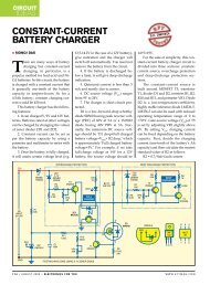
CIRCUIT<br />
IDEAS<br />
<strong>ULTRASONIC</strong> <strong>PROXIMITY</strong> <strong>DETECTOR</strong><br />
PRADEEP G.<br />
We the humans can hear<br />
sound of up to 20kHz frequency<br />
only. This proximity<br />
detector works at a frequency of 40<br />
kHz. It uses two specially made ultrasonic<br />
transducers: One transducer<br />
emits 40kHz sound, while the other<br />
receives 40kHz sound and converts it<br />
into electrical variation of the same frequency.<br />
Fig. 1 shows the block diagram of<br />
the ultrasonic proximity detector and<br />
Fig. 2 shows its circuit. Mount the<br />
transducers (transmitter as well as receiver)<br />
about 5 cm apart on a piece of<br />
Fig. 1: Block diagram of ultrasonic proximity detector<br />
general-purpose PCB as shown in<br />
Fig. 3 and connect to identical points<br />
(‘a’ through ‘d’) of the detector circuit<br />
(Fig. 2) via external wires.<br />
The 40kHz oscillator is built<br />
around transistors T1 and T2. If there<br />
is a solid object in front of the ultrasonic<br />
transmitter module (TX1), some<br />
signals will be reflected back and<br />
sensed by the receiver transducer<br />
(RX1). The 40kHz ultrasonic signals are<br />
converted into 40kHz electric signals<br />
by the receiver and then amplified by<br />
transistors T3 and T4.<br />
The amplified signals are still in<br />
the inaudible range, i.e., these can’t be<br />
heard. So a frequency-divider stage us-<br />
ing CMOS decade counter IC4017 (IC1)<br />
is used at the output of the amplifier.<br />
IC1 divides the input frequency by ’10,’<br />
so the 40kHz signal becomes 4 kHz,<br />
whi<strong>ch</strong> is within the audible range. The<br />
4kHz signals are fed to op-amp IC 741<br />
(IC2), whi<strong>ch</strong> is wired as an earphone<br />
amplifier.<br />
This circuit can be used as an electronic<br />
guard for the blind. Keep it<br />
(along with 9V battery) in their pocket<br />
with earphone plugged to their ear.<br />
The transducer modules should be directed<br />
towards<br />
the<br />
walking<br />
path. If<br />
any object<br />
comes up<br />
in front or<br />
nearby,<br />
they will<br />
S.C. DWIVEDI<br />
Fig. 3: Transducers mounted<br />
on the PCB<br />
Fig. 2: Circuit of ultrasonic proximity detector<br />
88 • DECEMBER 2006 • ELECTRONICS FOR YOU WWW.EFYMAG.COM
hear 4kHz sound through the earphone<br />
and can <strong>ch</strong>ange their path accordingly.<br />
One thing to be noted here is that<br />
while using this device, avoid the company<br />
of your pets. The reason is that<br />
pets can hear ultrasonic sound, whi<strong>ch</strong><br />
will irritate them and they will bark<br />
unnecessarily.<br />
EFY note. A similar device is used<br />
in some cars, su<strong>ch</strong> as Skoda’s Laura<br />
model, to help the drivers in backing<br />
CIRCUIT<br />
IDEAS<br />
up and avoid banging against some<br />
invisible objects. However, instead of<br />
earphones the sound in this case is<br />
heard through a speaker and there is<br />
also an LCD screen to visually assist<br />
the driver. <br />
WWW.EFYMAG.COM<br />
ELECTRONICS FOR YOU • DECEMBER 2006 • 89