VERSATILE WATER-LEVEL CONTROLLER
VERSATILE WATER-LEVEL CONTROLLER
VERSATILE WATER-LEVEL CONTROLLER
- No tags were found...

Create successful ePaper yourself
Turn your PDF publications into a flip-book with our unique Google optimized e-Paper software.
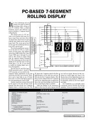
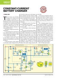
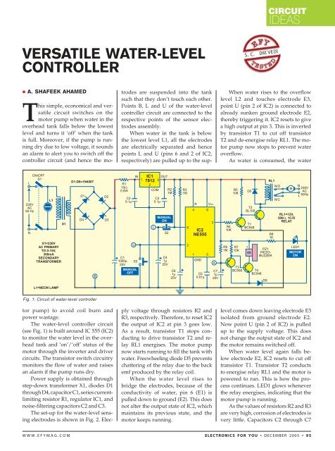
CIRCUITIDEAS<strong>VERSATILE</strong> <strong>WATER</strong>-<strong>LEVEL</strong><strong>CONTROLLER</strong>S.C. DWIVEDI• A. SHAFEEK AHAMEDWhen water rises to the overflowlevel L2 and touches electrode E3,point U (pin 2 of IC2) is connected toalready sunken ground electrode E2,thereby triggering it. IC2 resets to givea high output at pin 3. This is invertedby transistor T1 to cut off transistorT2 and de-energise relay RL1. The motorpump now stops to prevent wateroverflow.As water is consumed, the waterFig. 1: Circuit of water-level controllerThis simple, economical and versatilecircuit switches on themotor pump when water in theoverhead tank falls below the lowestlevel and turns it ‘off’ when the tankis full. Moreover, if the pump is runningdry due to low voltage, it soundsan alarm to alert you to switch off thecontroller circuit (and hence the motorpump) to avoid coil burn andpower wastage.The water-level controller circuit(see Fig. 1) is built around IC 555 (IC2)to monitor the water level in the overheadtank and ‘on’/‘off’ status of themotor through the inverter and drivercircuits. The transistor switch circuitrymonitors the flow of water and raisesan alarm if the pump runs dry.Power supply is obtained throughstep-down transformer X1, diodes D1through D4, capacitor C1, series currentlimitingresistor R1, regulator IC1, andnoise-filtering capacitors C2 and C3.The set-up for the water-level sensingelectrodes is shown in Fig. 2. Electrodesare suspended into the tanksuch that they don’t touch each other.Points B, L and U of the water-levelcontroller circuit are connected to therespective points of the sensor electrodesassembly.When water in the tank is belowthe lowest level L1, all the electrodesare electrically separated and hencepoints L and U (pins 6 and 2 of IC2,respectively) are pulled up to the supplyvoltage through resistors R2 andR3, respectively. Therefore, to reset IC2the output of IC2 at pin 3 goes low.As a result, transistor T1 stops conductingto drive transistor T2 and relayRL1 energises. The motor pumpnow starts running to fill the tank withwater. Freewheeling diode D5 preventschattering of the relay due to the backemf produced by the relay coil.When the water level rises tobridge the electrodes, because of theconductivity of water, pin 6 (E1) ispulled down to ground (E2). This doesnot alter the output state of IC2, whichmaintains its previous state, and themotor keeps running.level comes down leaving electrode E3isolated from ground electrode E2.Now point U (pin 2 of IC2) is pulledup to the supply voltage. This doesnot change the output state of IC2 andthe motor remains switched off.When water level again falls belowelectrode E2, IC2 resets to cut offtransistor T1. Transistor T2 conductsto energise relay RL1 and the motor ispowered to run. This is how the processcontinues. LED1 glows wheneverthe relay energises, indicating that themotor pump is running.As the values of resistors R2 and R3are very high, corrosion of electrodes isvery little. Capacitors C2 through C7WWW.EFYMAG.COMELECTRONICS FOR YOU • DECEMBER 2005 • 95
CIRCUITIDEASfilter out unwanted noise. Switches S2and S3 can be used to manually switchon and off the motor pump, respectively,when water is in between theupper and lower levels. Switch S1 isused to disable the unit during drypump run or while flushing the tank.For the sensor electrodes, use amoulded-type AC chord (used for taperecorders) with its pair of wires sleevedat the end and connected together toform the electrode. Other electrodes canbe made similarly. These three ACchords are suspended inside the tankfrom a longitudinally cut PVC pipe(used for electrical wiring).The arrangement for the dry pumpsensor is shown in Fig. 3. A mouldedtypeAC chord with its pair of wiressleeved at the end can be attached firmlyto the delivery pipe such that waterfalls onto the plug leads. The sleevedends are connected to points A and B ofthe water-level controller circuit.The circuit for dry-run alarm comprisestransistors T3 and T4,piezobuzzer PZ1, resistors R6 and R7,and capacitor C7. When points A andB of the dry-running sensor (see Fig.3) are bridged by water being deliveredby the pipe, transistor T3 conductsto drive transistor T4 into cutoffstate and therefore the DC buzzerremains silent.When the pump runs dry, pointsA and B are electrically apart causingtransistor T3 to cut off because of pullupresistor R6. Transistor T4 conductsdue to the emitter drop of transistorT3, which activates the DC buzzer toFig. 2: Water-level electrodes set-up for overheadtanksound an alarm indicating dry runningof the pump.The alarm circuit is enabled onlywhen transistor T2 conducts, i.e., onlywhen the motor pump runs. Diode D6isolates the relay driver circuitry toprevent transistor T3 from extendingground to the relay through transistorT3 and water being delivered. As soonas the pump is switched on, the alarmsounds until water reaches the deliveryport.House the controller circuit (includingthe power supply) in a cabinet.Use a four-core shielded cable forwiring the tank electrodes to the controllerunit fixed near the motor switch.To test the circuit, proceed as follows:1. Switch on power to the circuit.2. LED1 glows and relay RL1energises to produce an alarm frompiezobuzzer PZ1, indicating that noneof the circuit points A, B, U and L isshorted through water (i.e., water inthe tank is below the lowest limit). TheFig. 3: Dry pumpsensor set-upenergised relay indicates‘on’ statusof the motor.3. Immersepoints A and B inwater. The buzzerstops sounding toindicate that water is flowing out ofthe pipe to short points A and B. Thisconfirms no dry run.4. Immerse points B and L in water,as would be the case when thewater level rises. Momentarily touchpoint U to water. LED1 goes offand the relay de-energises to turnthe pump ‘off.’ This would be thecase when water touches the overflowlimit.5. Remove points A and B fromwater assuming that the flowing waterthat was shorting points A and Bhas stopped. Now, although water isnot flowing, the buzzer does not soundas the relay is already de-energised.6. Remove points U and B fromwater, assuming that water has fallenbelow the lowest limit because of consumption.Two seconds later, LED1glows and the relay energises.Precautions. 1. Make sure that waterbeing delivered from the water pipedoesn’t touch any of the suspendedwater-level sensors.2. Mount the alarm sensor firmlyonto the water pipe such that electrodesA and B are shorted by waterflowing out of the pipe.3. Use a properly shielded cable tocarry signals from the tank to the water-levelcontroller unit. •96 • DECEMBER 2005 • ELECTRONICS FOR YOU WWW.EFYMAG.COM