MUSICAL LIGHT CHASER
MUSICAL LIGHT CHASER
MUSICAL LIGHT CHASER

You also want an ePaper? Increase the reach of your titles
YUMPU automatically turns print PDFs into web optimized ePapers that Google loves.
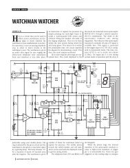
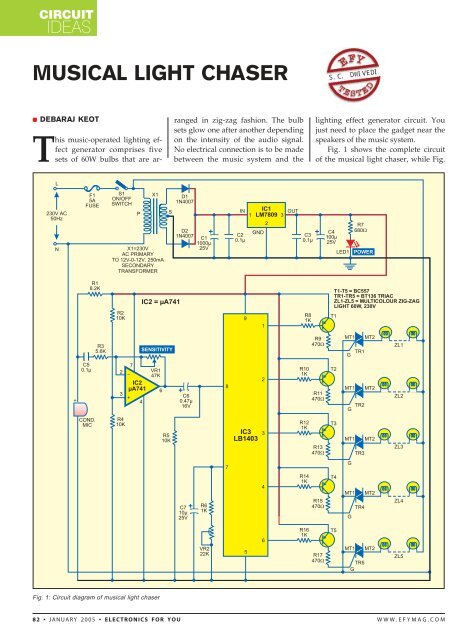
CIRCUITIDEAS<strong>MUSICAL</strong> <strong>LIGHT</strong> <strong>CHASER</strong>S.C. DWIVEDI• DEBARAJ KEOTThis music-operated lighting effectgenerator comprises fivesets of 60W bulbs that are ar-ranged in zig-zag fashion. The bulbsets glow one after another dependingon the intensity of the audio signal.No electrical connection is to be madebetween the music system and thelighting effect generator circuit. Youjust need to place the gadget near thespeakers of the music system.Fig. 1 shows the complete circuitof the musical light chaser, while Fig.Fig. 1: Circuit diagram of musical light chaser82 • JANUARY 2005 • ELECTRONICS FOR YOU WWW.EFYMAG.COM
2 shows pin configurations of 9V regulator7809, triac BT136 and level meterIC LB1403.The circuit is powered by regulated9V DC. The AC mains is stepped downby transformer X1 to deliver a secondaryoutput of 12V AC at 250 mA. Thetransformer output is rectified by afull-wave rectifier comprising diodesD1 and D2 and filtered by capacitorsC1 and C2. Regulator IC 7809 (IC1)provides regulated 9V power supplyto the circuit. Closing switch S1 providespower to the circuit and LED1glows to indicate that the circuit isready to work.When you put your music systemin front of the condenser microphoneof the light chaser, the sound pressurevariation is converted into electricalsignals by the condenser microphone.These weak electrical signals are amplifiedby op-amp µA741 (IC2), whichis configured as an inverting amplifier.Using preset VR1 you can set thesensitivity of the circuit.The amplified output is fed to ICLB1403 (IC3) at its input pin 8. IC3 is afive-dot LED level meter commonlyused in stereo systems for LEDbargraph displays. It has a built-in am-Fig. 2: Pin configurationplifier, comparators and constant currentsource at its output pins.Depending on the intensity of theinput audio signals, all or some outputsof IC3 go low to drive transistorsT1 through T5, which, in turn, fire thecorresponding triacs TR1 through TR5via their gates and multicoloured zigzagbulb sets comprising ZL1 throughZL5 glow.When the audio level is low, onlytriac T1 is fired and the zig-zag bulbset ZL1 turns on and off sequentially.When the audio level is high, triacsTR1 through TR5 get fired and all thebulb sets (ZL1 through ZL5) turn onand off sequentially.Pin 7 of IC3 is used for selectingthe response speed of the lighting.The larger the time constant, theslower the response, and vice versa.CIRCUITIDEASThe time constant can be changed bychanging the values of resistor R6,variable resistor VR2 and capacitorC7. Here, variable resistor VR2 is usedfor varying the response speed of thechaser light as desired. When VR2 isset in the minimum resistance position,the response is very fast, andwhen it is set at the maximum resistance,the response is slow.The complete circuit including thepower supply can be constructed onany general-purpose PCB ora small Vero board. Triacs TR1through TR5 should be kept awayfrom the op-amp and its related components.The metallic parts of thetriacs should not touch each other andthe other parts of the circuit. Afterassembling the circuit, house it in asuitable shockproof plastic cabinet.Make some holes in the cabinet forheat dissipation.Note. 1. Some zig-zag lights havea special bulb called ‘master bulb’ forautomatic flickering. It should beremoved and replaced with a simplenon-flickering colour bulb.2. Never touch any naked part ofthe circuit when it is connected to themains. •WWW.EFYMAG.COMELECTRONICS FOR YOU • JANUARY 2005 • 83