Power Supplies as Voltage and Current Sources
Power Supplies as Voltage and Current Sources
Power Supplies as Voltage and Current Sources

You also want an ePaper? Increase the reach of your titles
YUMPU automatically turns print PDFs into web optimized ePapers that Google loves.
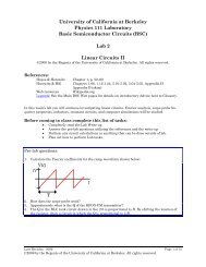
Eleg. 2111 Laboratory 2<strong>Power</strong> <strong>Supplies</strong> <strong>as</strong> <strong>Voltage</strong> <strong>and</strong> <strong>Current</strong> <strong>Sources</strong>Pre-LabI. The power grid <strong>and</strong> earth ground.Most of the electric power we use is distributed through the power grid, anetwork of conductors that brings an alternating voltage to our electrical outlets.When a load 1 is connected across the terminals of these outlets, current flowsthrough it driven by the potential difference.For safety <strong>and</strong> other re<strong>as</strong>ons it is desirable to be able to know with confidencethe potential between any two points in the grid, <strong>and</strong> between any point in the grid<strong>and</strong> points not in the grid. To accomplish this requires a common voltagereference, <strong>and</strong> this reference h<strong>as</strong> been chosen to be the earth itself. This choice ismade because the earth is conductive <strong>and</strong> available everywhere the power gridexists. 2 A connection to the earth is available at the ground terminal of everymodern electric outlet (the round connector of the plug-in), <strong>and</strong> is called the“earth ground.” The conductor connected to this ground terminal shouldeventually lead 3 to a connection to the earth. The physical form of the earthconnection may vary. The ground conductor may be clamped to a copper-cladrod driven deep into the earth, to metal structural supports buried or driven intothe ground, or to other conducting structures in intimate contact with the earth.II. <strong>Power</strong> <strong>Supplies</strong>Although electric power is distributed in the form of alternating current, mostelectronics operates on direct current. Circuits which convert the AC powersupplied at electric outlets to DC power suitable for electronic equipment arecalled power supplies. <strong>Power</strong> supplies may be built-in parts of the equipmentthey power, or they may be manufactured on a separate board <strong>and</strong> mounted intheir own cabinets. Bench supplies, such <strong>as</strong> those used in this course, areintended to be used for test <strong>and</strong> development. The DC voltage they supply isusually variable <strong>and</strong> available at terminals on the front panel. Many have built-inmeters to monitor the supplied voltage <strong>and</strong> current.Bench supply circuit boards are usually mounted in a metal box, or ch<strong>as</strong>sis, whichis connected to the earth ground of the three wire power cord to improve safety.If a malfunction should place dangerous voltages on the ch<strong>as</strong>sis, the currentdrawn by the low impedance ground connection will either trip a circuit breakeror significantly lower the ch<strong>as</strong>sis voltage. The power supply circuit is constructedto produce a DC potential only between the + <strong>and</strong> – (or HI <strong>and</strong> LO) panelterminals without reference to earth ground. The potential of the terminals withrespect to ground is not known; they are said to be “floating.” A connection tothe earth ground is usually brought to the front panel along with the DC voltageterminals so that it is e<strong>as</strong>ily accessible if needed.1 Anything that conducts a non-negligible amount of current when line potential is applied.2 The choice of the surface of the earth, which varies in conductivity, <strong>as</strong> a reference leads to other problemswhich involve the art <strong>and</strong> science of grounding of electric power systems. These considerations are farbeyond the scope of this course.3 Perhaps through some connections.
Figure 1. Shows a conceptual model of a DC bench supply. The “circles”represent the front panel connections. The ideal voltage source indicates that thepower supply circuit holds the HI terminal at some positive DC potential withrespect to the LO terminal. The terminal labeled EGND is connected inside thesupply to the earth ground.DC <strong>Power</strong> SupplyHILOEGNDFigure 1. Conceptual model of a bench power supply.Often, a bipolar supply, supplying both positive <strong>and</strong> negative DC voltages withrespect to some reference, is desired. Two supplies of the type shown in Figure 1.can be connected to produce the desired supply <strong>as</strong> shown in Figure 2.DC <strong>Power</strong> Supply #1DC <strong>Power</strong> Supply #2HILOEGNDHILOEGNDVCCVCCVCC+ V REF- VFigure 2. A bipolar supply1. Explain why the negative terminal of <strong>Power</strong> Supply #1 may be connected tothe positive terminal of <strong>Power</strong> Supply #2 without excessive current flowing.(Make an argument b<strong>as</strong>ed on Figure 3. Here, loads are shown between eachof the supply voltages <strong>and</strong> REF. The connection between HI of supply #2 <strong>and</strong>LO of supply #1 h<strong>as</strong> been replaced by a resistance Rref. Use Kirchoff’scurrent law to argue that the current through Rref, <strong>and</strong> hence the voltageacross it, is zero. What may be concluded from this fact?) B<strong>as</strong>e yourargument on answers to the following questions:
a) Trace clockwise from IL#1 around the loop containing Load #1. Whatis the value of Iaa?b) Trace counter-clockwise from IL#1 around the same loop. What is thevalue of Ia?c) What must be the value of the current in Rref? Explain.d) Note that a similar argument may be made regarding the “Load #2loop. Do not make the argument.DC <strong>Power</strong> Supply #1DC <strong>Power</strong> Supply #2HILOEGNDHILOEGNDAREFRrefBIbbIL#1VCC+ V Iaa- VIbIaVCCVCCIL#2Load #1Load #2Figure 3. Bipolar supply with currents shown.The bipolar supply of Figure 2. will supply both positive <strong>and</strong> negative voltageswith respect to the reference <strong>as</strong> desired, but it is still not referenced to earthground. Though this may be perfectly acceptable in many situations, in others itmay be desirable to provide an earth ground reference. 4 In this c<strong>as</strong>e, we maysimply connect the reference (REF) to the earth ground terminals of either (orboth) of the power supplies, <strong>as</strong> shown in Figure 4.4 Particularly if an earth reference already exists in some of the me<strong>as</strong>urement instruments to be used toanalyze the circuit under test. This is the c<strong>as</strong>e for the oscilloscopes you will use later.
DC <strong>Power</strong> Supply #1 DC <strong>Power</strong> Supply #2HILOEGNDHILOEGNDV+VCCVCCREFVCCV-Figure 4. Bipolar supply referenced to earth ground.Finally, suppose that, to be really sure that both supplies have a ground reference,suppose we connect both of the LO terminals to earth ground. 5 The resultingcircuit is shown in Figure 5.2. Explain why the circuit of Figure 5 is a problem.THE MORAL: Be sure you know how your supplies are connected internally, becareful <strong>and</strong> think before you connect.DC <strong>Power</strong> Supply #1 DC <strong>Power</strong> Supply #2HILOEGNDHILOEGNDV+VCCVCCREFVCCV-Figure 5. A “bipolar supply” with both LO terminals at earth ground.An ideal voltage source maintains a constant potential between its terminals <strong>and</strong>will supply <strong>as</strong> much current <strong>as</strong> is required to do so. Modern real power suppliesuse internal electronics to approximate this ideal over a wide range of currents,but not, of course, for all currents. There is usually a maximum current value(called the current limit) at which the voltage falls to zero over a very small range5 Some power supplies are connected like this internally.
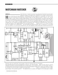
of currents. This protects the supply from damage in c<strong>as</strong>e it is short-circuited.Good quality bench supplies allow the operator to set both the operating voltage<strong>and</strong> the current limit, <strong>and</strong> means are provided to notify the operator that thecurrent limit h<strong>as</strong> occurred (usually an indicator light).Figure 6. is a graph of the voltage-current characteristic of a typical voltagesource with voltage set to 5 volts <strong>and</strong> the current limit set to 40 ma. On the rangeof currents from zero to about 40 ma, the curve of voltage versus current is almosthorizontal, approximating constant voltage independent of current. After currentlimit is reached, the voltage falls to zero in short range of current. On this portionof the graph, the curve is almost vertical, approximating constant currentindependent of voltage.On the horizontal portion of the V-I curve of Figure 6, the supply approximates afive-volt voltage source. On the vertical portion of the curve, it approximates a 40ma current source. Within limits, the supply can be set up to act <strong>as</strong> either avoltage or current source for some range of loads by setting the supply voltage<strong>and</strong> the current limit.6.0VTypical V-I Characteristic of a <strong>Power</strong> Supply4.0V2.0V0V-2.0V0A 5mA 10mA 15mA 20mA 25mA 30mA 35mA 40mA 45mAV(U1A:-)I_I1Figure 6. Typical V-I characteristic of a bench power supply with the voltage set atabout 5 volts <strong>and</strong> the current limit set at about 40.7 ma.= <strong>and</strong>,according to Ohm’s law, the V-I curve for a resistor may be expressedsymbolically <strong>as</strong> V = IR . Consider a resistor connected to a power supply.Clearly, the resistor voltage must be equal to the power supply terminal voltage,<strong>and</strong> the resistor current must be equal to the power supply current. The voltage<strong>and</strong> current at which this occurs, which is called the operating point, may beThe V-I curve of Figure 6 may be expressed symbolically <strong>as</strong> V f ( I)= <strong>and</strong> V = IR . Thissolution may be found graphically by plotting both of these equations on the sameset of axes <strong>and</strong> noting where they cross, <strong>as</strong> in figure 7, where the V-Icharacteristic of a 167 Ω resistor h<strong>as</strong> been plotted on the V-I curve of the powersupply.found by simultaneous solution of the equations V f ( I)
Laboratory ProcedureI. <strong>Voltage</strong>-<strong>Current</strong> characteristic of the bench supplyDC <strong>Power</strong> Supply123456HILOEGNDFluke MeterDecade BoxBench Multi-meterR1123456HILO1kFigure 8. Experimental set-up for Lab 21. Connect the power supply, the decade resistance box, <strong>and</strong> the Fluke h<strong>and</strong>-heldmulti-meter <strong>as</strong> shown in Figure 8. Set the decade box at a resistance of 0.5 K, <strong>and</strong>connect the Bench Multi-meter across the power supply terminals. Rotate the“voltage” control to its maximum counter-clockwise position <strong>and</strong> the “current”control to its maximum clockwise position.2. The power supply V-I curve will be me<strong>as</strong>ured <strong>and</strong> plotted for a maximum voltageof 15 volts <strong>and</strong> a maximum current of 10 ma. Prepare an appropriate set of axesin your lab notebook to plot the data <strong>as</strong> it is me<strong>as</strong>ured.3. Set the supply voltage to 15 volts ± 1%<strong>as</strong> me<strong>as</strong>ured by the bench multi-meter.4. Rotate the “current” control counter-clockwise until the Fluke meter reads 10 ma± 1% .5. Successively set the decade resistance box to values of 20000, 10000, 5000, 3300,2500, 1600, 1200, 800, 400 <strong>and</strong> 200 ohms. Record, <strong>and</strong> plot on your set of axes,the power supply voltage <strong>and</strong> current for each decade-box setting.a) Over what range of loads does the power supply approximate a voltagesource? 6 Find the average voltage over this range of loads. Find themaximum percentage deviation from the average over this range of loads.b) Over what range of loads does the power supply approximate a currentsource? Find the average current over this range of loads. Find themaximum percentage deviation from the average over this range of loads.c) Does the supply do a better job of approximating a current source or avoltage source? Would you guess the supply w<strong>as</strong> designed to be used <strong>as</strong> acurrent source? Explain.d) Other than use <strong>as</strong> a current source, why is a current control desirable?6 Some loads may represent a transition between voltage source <strong>and</strong> current source operation, i.e., thesupply may act <strong>as</strong> neither a voltage nor a current source for some loads.
6. Show your instructor your data <strong>and</strong> the V-I curve you have plotted in yournotebook before leaving the laboratory.7. Using a method similar to that given in steps 1 through 4, set the power supply toapproximate a 25 volt source over some range of loads, <strong>and</strong> to approximate acurrent source of 15 ma for some other range.a) Devise <strong>and</strong> perform an experiment to find the range of loads over whichthe supply acts <strong>as</strong> a voltage source, <strong>and</strong> the range of loads over which itacts <strong>as</strong> a current source, for this setting. List <strong>and</strong> explain each step in yourprocedure. Report the raw data <strong>and</strong> the range of loads for each mode.Report nominal values (do not report an estimated error).b) Over what range of loads does the power supply approximate a voltagesource? Find the average voltage over this range of loads. Find themaximum percentage deviation from the average over this range of loads.c) Over what range of loads does the power supply approximate a currentsource? Find the average current over this range of loads. Find themaximum percentage deviation from the average over this range of loads.