PMS 4500 FCB Manual - Ysebaert
PMS 4500 FCB Manual - Ysebaert
PMS 4500 FCB Manual - Ysebaert

Create successful ePaper yourself
Turn your PDF publications into a flip-book with our unique Google optimized e-Paper software.
Installation manual<br />
Installation, Maintenance and Troubleshooting<br />
<strong>PMS</strong>_<strong>4500</strong>_<strong>FCB</strong>_manual.V02 15.7.05<br />
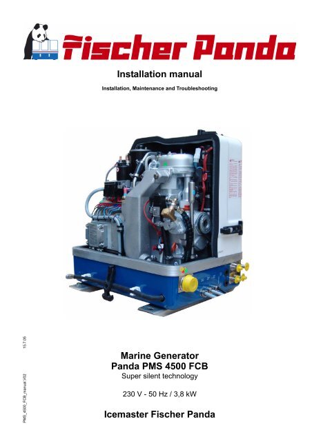
Marine Generator<br />
Panda <strong>PMS</strong> <strong>4500</strong> <strong>FCB</strong><br />
Super silent technology<br />
230 V - 50 Hz / 3,8 kW<br />
Icemaster Fischer Panda
Current revision status<br />
Document<br />
Actual:<br />
Replace:<br />
<strong>PMS</strong>_<strong>4500</strong>_<strong>FCB</strong>_manual.V02_15.7.05<br />
<strong>PMS</strong>_<strong>4500</strong>_<strong>FCB</strong>_manual_29.10.04<br />
Revision<br />
Page<br />
Chapter C.2.2 Picture of VCS deleted 29<br />
Chapter C.3.1 Picture changed 30<br />
Chapter C.8.3 Pictures changed 60<br />
Chapter C.8.4 Picture and text changed 61<br />
ii
25 20 10 10 10<br />
since 1977<br />
Icemaster GmbH<br />
since 1978<br />
Fischer Marine<br />
Generators<br />
since 1988<br />
Conclusion Fischer -<br />
Icemaster GmbH<br />
since 1988<br />
100 % water cooled<br />
Panda generators<br />
since 1988<br />
Panda Vehicle<br />
Generators<br />
Fischer Panda<br />
FISCHER GENERATORS have been manufactured since 1978 and are a well-known brand for first class diesel generators<br />
with especially effective sound-insulation.<br />
Fischer has been one of the leading manufacturers in respect of quality and know-how during this period.<br />
FISCHER, as the worldwide manufacturer of modern marine diesel generators, developed the Sailor-Silent series for<br />
example and produced a GFK sound-insulated capsule as early as 1979 and the basis for new generator technology.<br />
The companies Fischer and Icemaster amalgamated under the direction of Icemaster in 1988, in order to concentrate<br />
on the development of new products. Production was moved to Paderborn.<br />
The amalgamation of the two qualified companies led to the development of a complete new programme within a short<br />
space of time. The gensets developed at that time set new technological standards worldwide.<br />
The gensets became more efficient and powerful than other gensets in the same nominal performance range, because<br />
of the improved cooling. Panda generator demonstrated its superiority in several tests by renowned institutes and<br />
magazines during the past years. The patented VCS (voltage Control System) means it can meet all demands including<br />
motor speed. The start-booster (ASB) means Panda generators meet the highest demands in respect of voltage stability<br />
and starting values A Panda generator, with the same drive motor, produces 15% more effective output than the<br />
majority of conventional generators. This superiority in efficiency also ensures a fuel saving to the same extent.<br />
The 100% water-cooled Panda gensets are currently manufactured in the performance range from 2 to 100 kW in<br />
various versions. Fast running motors are preferred for performances up to approx 30 kW (Nominal speed 3000 rpm).<br />
The heavier slow runners are preferred for the higher range. The fast running gensets have proved themselves many<br />
times for many uses, that they meet the demands in quality of yachts and vehicles, and offer space and weight saving<br />
of 50% compared to slow running generators.<br />
In addition to the Panda series, Icemaster also supply the super compact high-tech sound-insulated battery charging<br />
genset from the DC/AC Panda AGT series, which is a very interesting solution for the production of mobile power.<br />
The new HTG-alternators ensure that a charging rate of 285 amps is achieved that was scarcely thought possible for<br />
this compact construction. This alternator replaces a separate shipboard generators (constant 230 volts AC with up to<br />
3500 kW from the main machine)<br />
ICEMASTER GmbH, 33104 Paderborn, reserves all rights regarding text and graphics. Details are given to the best of our knowledge. No liability is accepted for correctness.<br />
Technical modifications for improving the product without previous notice may be undertaken without notice. Before installation, it must be ensured that the Pictures,<br />
diagrams and related material are applicable to the genset supplied. Enquiries must be made in case o doubt.<br />
iii
CALIFORNIA<br />
Proposition 65 Warning<br />
Diesel engine exhaust and some of its constituents<br />
are known to the State of California to cause cancer,<br />
birth defects, and other reproductive harm.<br />
Attention, Important Directions regarding Operation!<br />
1. The installation certificate must be completed when taken into use, and certified by a signature.<br />
2. The installation certificate must be despatched within two weeks of use to ICEMASTER.<br />
3. The official guaranty confirmation will be completed by ICEMASTER after receipt and sent to the customer.<br />
4. A guaranty must be shown to make any claims.<br />
Claims against the guaranty will not be accepted of the above said instructions are not, or only partially, carried out.<br />
Manufacturer declaration in terms of the machine guideline 98/37/EG .<br />
The generator is in such a way developed that all assembly groups correspond to the CE guidelines. If machine guideline<br />
98/37/EG is applicable, then it is forbidden to bring the generator into operation until it has been determined<br />
that the system into which the generator is to be installed in also corresponds to the regulations of the machine guideline<br />
98/37/EG. This concerns among other things the exhaust system, cooling system and the electrical installation.<br />
The evaluation of the "protection against contact" can only be accomplished in connection with the respective<br />
system. Likewise among other things responsibility for correct electrical connections, a safe ground wire connection,<br />
foreign body and humidity protection, protection against humidity due to excessive condensation as well as the overheating<br />
through appropriate and inappropriate use in its installed state on the respective machine lies within the<br />
responsibility of those who undertake installation of the generator in the system.<br />
Use the advantages of the customer registration:<br />
• Thus you receive to extended product informations, which are sometimes safety-relevant<br />
• you receive, if necessarily free Upgrades<br />
Far advantages:<br />
By your full information Fischer Panda technicians can give you fast assistance, since 90% of the disturbances result<br />
from errors in the periphery.<br />
Problems due to errors in the installation can be recognized in the apron.<br />
Technical Support by Internet:<br />
info@fischerpanda.com<br />
iv
Safety Instructions<br />
The electrical Installations may only be carried out be trained and<br />
tested personnel!<br />
The generator may not be taken into use with the cover removed.<br />
The rotating parts (belt-pulley, belts, etc) must be so covered and protected do that there is no danger to life and<br />
body!<br />
If a sound insulation covering must be produced at the place of installation, then well-placed signs must show that<br />
the generator can only be switched on with a closed capsule.<br />
All servicing-, maintenance or repair work may only carried out, when the motor is not running.<br />
Electrical voltages above 48 volts ( battery chargers greater than 36 volts) are always dangerous to life). The rules of<br />
the respective regional authority must be adhered to. Only an electrician may carry out installation of the electrical<br />
connections for safety reasons.<br />
Protective Conductor:<br />
The generator is „earthed " as standard (The centre and earth are connected by means of a bridge in the generator<br />
terminal box). This is a basic safety function, which offers basic safety as long as no other component has been<br />
installed. It is, above all, conceived for supply and an eventual test run.<br />
This "earth" (PEN) is only effective, if all parts of the electrical system is earthed, and has a common “potential”. The<br />
bridges can be removed, if this is required for technical reasons and another protection system has been installed.<br />
The full voltage is exploited at the AC control box, when the generator is run. It must therefore be ensured<br />
that the control box is closed and cannot be tampered with, if the generator is running.<br />
The battery must always be disconnected, if work on the generator or electrical system is to be carried out,<br />
so that the generator cannot be unintentionally started.<br />
It is not allowed to disconnect the battery during operation!<br />
After the generator has stopped the battery can be disconnected!<br />
Switch off all load when working on the generator<br />
All load must be disconnected, in order to avoid damages to the devices. In addition the semi conductors in the AC<br />
control box must be disconnected in order to avoid the boat capacitors being activated. The minus pole of the battery<br />
ought to be removed.<br />
Capacitors are required to run the generator. These have two varying functions:<br />
A) The working capacitors<br />
B) The (Booster) capacitors<br />
Both Groups are located in a separate AC-Control box.<br />
Capacitors are electrical stores. There could be a residual of high electrical current at the contacts for a period disconnection<br />
from the circuit. The contacts my not be touched for safety reasons, If the capacitors are to be exchanged<br />
or checked, then a short circuit between the contacts should be made so that the stored energy is discharged.<br />
If the generator is switched off in the normal manner, the working capacitors are automatically discharged by means<br />
of the windings. The booster capacitors are discharged by means of internal discharge resistors.<br />
All capacitors must be short-circuited before work is carried out on the AC-Control box for safety reasons.<br />
v
Table of contents<br />
A Mode of Operation of the Generator ................................................................................5<br />
A.1 Mode of operation of operating surveillance ...................................................................... 5<br />
A.1.1 Regulation of the generator voltage by the VCS ....................................................................... 7<br />
A.1.2 Overloading of engine during longer operation ......................................................................... 7<br />
A.2 Operation of electric motors with high starting current .................................................... 7<br />
A.2.1 General references.................................................................................................................... 7<br />
A.2.2 Compensation of 1 phases engines .......................................................................................... 8<br />
A.2.3 Compensation of 3 phases engines .......................................................................................... 8<br />
A.3 Operation of the generator with additional units ............................................................... 8<br />
A.3.1 General references.................................................................................................................... 8<br />
A.4 Operation of the generator with HTG generator ................................................................. 9<br />
A.4.1 General references.................................................................................................................... 9<br />
A.5 Operation of generator with installation under the waterline ........................................... 9<br />
A.5.1 Control of the ventilation valve ................................................................................................ 10<br />
A.6 Operation of generator with installation over the waterline ............................................ 11<br />
B Maintenance Instructions ................................................................................................13<br />
B.1 General maintenance instructions .................................................................................... 13<br />
B.1.1 Checks before starting ............................................................................................................ 13<br />
B.1.2 Hose elements and rubber formed component in the sound cover......................................... 13<br />
B.2 Oil circuit maintenance ....................................................................................................... 13<br />
B.3 Execution of an oil change ................................................................................................. 14<br />
B.3.1 De-aerating the fuel system .................................................................................................... 16<br />
B.3.2 Exchange of the fuel filter........................................................................................................ 16<br />
B.4 Checking the water separator in the fuel supply ............................................................. 17<br />
B.4.1 Exchange the air filter mat....................................................................................................... 17<br />
B.5 De-aerating of the coolant circuit / freshwater ................................................................. 18<br />
B.5.1 Draining the coolant ................................................................................................................ 20<br />
B.5.2 Exchange of the toothed-belt for the internal cooling water pump .......................................... 20<br />
B.6 The raw water circuit ........................................................................................................... 21<br />
B.6.1 Clean raw water filter............................................................................................................... 21<br />
B.7 Causes with frequent impeller waste ................................................................................ 22<br />
B.7.1 Exchange of the impeller......................................................................................................... 22<br />
B.8 Coolant connection block at generator housing .............................................................. 24<br />
B.9 Conservation at longer operation interruption ................................................................. 25<br />
B.9.1 Measures on preparation of the winter storage....................................................................... 25<br />
B.9.2 Initiation at spring .................................................................................................................... 26<br />
C Generator Failure .............................................................................................................27<br />
C.1 Tools and measuring instruments ..................................................................................... 27<br />
C.2 Overloading the Generator ................................................................................................. 27<br />
C.2.1 Monitoring the Generator Voltage ........................................................................................... 28<br />
C.2.2 Automatic Voltage Monitoring and Auto-Shut Down ............................................................... 28<br />
15.7.05 <strong>PMS</strong>_<strong>4500</strong>_<strong>FCB</strong>_manual.V02 - Table of contents - Page 1
C.3 Low Generator-Output Voltage ..........................................................................................30<br />
C.3.1 Discharge the capacitors ........................................................................................................ 30<br />
C.3.2 Checking the capacitors ......................................................................................................... 31<br />
C.3.3 Checking the generator voltage.............................................................................................. 32<br />
C.3.4 Measuring the coil resistance ................................................................................................. 32<br />
C.3.5 Checking the coil(s) to short-circuit ........................................................................................ 33<br />
C.3.6 Measuring the inductive resistance ........................................................................................ 33<br />
C.4 Generator provides no Voltage ..........................................................................................34<br />
C.4.1 Rotor Magnetism Loss and "Re-magnetizing" ........................................................................ 34<br />
C.5 Starting Problems ................................................................................................................34<br />
C.5.1 Starting with a weak Battery ................................................................................................... 34<br />
C.5.2 Fuel Solenoid Valve................................................................................................................ 35<br />
C.5.3 Troubleshooting Table............................................................................................................ 36<br />
D Installation Instructions .................................................................................................. 37<br />
D.1 Placement .............................................................................................................................37<br />
D.1.1 Placement and Basemount .................................................................................................... 37<br />
D.1.2 Notice for optimal sound insulation......................................................................................... 37<br />
D.2 Generator Connections - Scheme ......................................................................................38<br />
D.3 Cooling System Installation - Raw water ..........................................................................39<br />
D.3.1 General References ............................................................................................................... 39<br />
D.3.2 Installation of the thru-vessel fitting in Yachts ........................................................................ 39<br />
D.3.3 Quality of the raw water sucking in line .................................................................................. 39<br />
D.3.4 Installation above waterline .................................................................................................... 40<br />
D.3.5 Installation below waterline..................................................................................................... 41<br />
D.3.6 Installation under the waterline............................................................................................... 42<br />
D.3.7 Installation over the waterline ................................................................................................. 43<br />
D.4 The Freshwater - Coolant Circuit .......................................................................................44<br />
D.4.1 Position of the external Cooling Water Expansion Tank ........................................................ 44<br />
D.4.2 Scheme for fresh water circuit ................................................................................................ 44<br />
D.4.3 De-aerating at the first filling of the internal cooling water circuit ........................................... 45<br />
D.4.4 Filling and de-aerating of the internal cooling water circuit..................................................... 46<br />
D.4.5 Pressure test for control of cooling water circuit..................................................................... 47<br />
D.5 Watercooled Exhaust System ............................................................................................48<br />
D.5.1 Installation of the standard exhaust system ........................................................................... 48<br />
D.5.2 Exhaust / water separator....................................................................................................... 49<br />
D.5.3 Installation exhaust/water separator....................................................................................... 50<br />
D.6 Fuel System Installation .....................................................................................................51<br />
D.6.1 General References ............................................................................................................... 51<br />
D.6.2 The electrical fuel pump ......................................................................................................... 52<br />
D.6.3 Connection of the fuel lines at the tank .................................................................................. 52<br />
D.6.4 Position of the pre-filter with water separator ......................................................................... 53<br />
D.6.5 De-aerating the fuel system.................................................................................................... 53<br />
D.7 Generator 12V DC System-Installation ..............................................................................54<br />
D.7.1 Connection of the 12V starter battery..................................................................................... 54<br />
D.7.2 Connection of the remote control panel.................................................................................. 55<br />
D.7.3 The speed sensor................................................................................................................... 56<br />
D.7.4 Electronic starter control unit .................................................................................................. 56<br />
D.8 Generator AC System-Installation .....................................................................................57<br />
D.8.1 Installation with looped in AC-Control box.............................................................................. 57<br />
D.8.2 Installation AC-Box / distribution panel separate connected .................................................. 58<br />
Page 2 <strong>PMS</strong>_<strong>4500</strong>_<strong>FCB</strong>_manual.V02 - Table of contents 15.7.05
D.8.3 AC-Control box with VCS and ASB......................................................................................... 60<br />
D.8.4 Booster electronic.................................................................................................................... 61<br />
D.8.5 Jump start at hight starting current (Booster) .......................................................................... 62<br />
D.9 Insulation test ...................................................................................................................... 62<br />
D.10 Voltage controller ................................................................................................................ 63<br />
D.10.1 Adjustment of the rated voltage............................................................................................... 63<br />
D.10.2 Functional decription of the voltage controller......................................................................... 63<br />
D.10.3 Time lag of the switching points .............................................................................................. 64<br />
F<br />
Tables ...................................................................................................................................I<br />
F.1 Troubleshooting ..................................................................................................................... I<br />
F.2 Technical Data Engine ..........................................................................................................V<br />
F.3 Technical Data Generator ....................................................................................................VI<br />
F.4 Types of coil ........................................................................................................................VII<br />
F.5 Inspection checklist for services ......................................................................................VIII<br />
F.6 Engine oil ..............................................................................................................................IX<br />
F.7 Coolant ...................................................................................................................................X<br />
F.8 Capsule Measurements .......................................................................................................XI<br />
F.9 Cooling water flow Panda <strong>4500</strong> <strong>FCB</strong> .................................................................................XII<br />
15.7.05 <strong>PMS</strong>_<strong>4500</strong>_<strong>FCB</strong>_manual.V02 - Table of contents - Page 3
Page 4 <strong>PMS</strong>_<strong>4500</strong>_<strong>FCB</strong>_manual.V02 - Table of contents 15.7.05
Mode of Operation of the Generator<br />
A. Mode of Operation of the Generator<br />
A.1 Mode of operation of operating surveillance<br />
Internal monitoring switches<br />
The generator is equipped about failure switches, which are indicated on the remote control<br />
panel, and also about failure switch, which switch-off the generator automatically without indicating<br />
a failure in the remote control panel:<br />
The remote control panel supervised the following values. In the case of a disturbance the generator<br />
is switched off, in order to avoid damage to the aggregate:<br />
1. Cooling water temperature at cylinder head and exhaust connection<br />
2. Coil temperature<br />
3. Oil pressure<br />
The fault is transmitted, if one of these switches measures a value that exceeds the required<br />
value (all switches are openers). The current is switched off by the main relay. (Fuel magnet<br />
valve closes, the fuel suction pump is switched off, VCS is switched off).<br />
The combustion engine possesses an oil pressure control switch, which switches the engine off if<br />
the oil pressure drops under a certain value.<br />
The additional failure switch in the generator coil, it is not indicated at the remote control panel,<br />
interrupts directly the current supply to the main power relay. By this constellation it is guaranteed<br />
that the generator switches off in each case when an error is present.<br />
This measure is, if possibly, a circuit at the remote control panel failed.<br />
Thermo-switch at cylinder head<br />
15.7.05 <strong>PMS</strong>_<strong>4500</strong>_<strong>FCB</strong>_manual.V02 - Chapter A: Mode of Operation of the Generator Page 5
Mode of Operation of the Generator<br />
Thermo-switch exhaust elbow<br />
If the impeller pump should fail, the raw<br />
water stream fed here tears off and the<br />
exhaust elbow heats up immediately<br />
extremely fast, since the cooling water is<br />
missing. The thermo-switch supervises<br />
thus a functioning raw water cycle.<br />
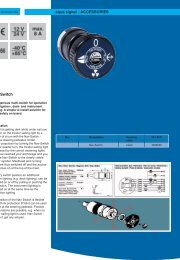
Thermo-switch in the generator coil<br />
1<br />
2<br />
3<br />
1. Generator coil<br />
2. Thermo-switch<br />
3. Housing<br />
For the protection of the generator coil<br />
there are two thermo-switches inside the<br />
coil, which are for inserted parallel and<br />
safety's sake independently from each<br />
other.<br />
Fig. A.1: Thermo-switch coil<br />
Oil pressure switch<br />
The combustion engine possesses an oil<br />
pressure control switch, which switches<br />
the engine off if the oil pressure drops<br />
under a certain value.<br />
Page 6 <strong>PMS</strong>_<strong>4500</strong>_<strong>FCB</strong>_manual.V02 - Chapter A: Mode of Operation of the Generator 15.7.05
Mode of Operation of the Generator<br />
A.1.1 Regulation of the generator voltage by the VCS<br />
The output voltage of the generator is permanently measured by the VCS (approx. 20 times per<br />
second!). As soon as by a consumer the voltage is affected, the speed regulation provides to<br />
adapt to the changed power demand by appropriate change of the engine speed. Not only by the<br />
excitation of the generator it is worked against to the initiating voltage drop, but also by the raising<br />
of the number of revolutions whereby the drive potential improves.<br />
A.1.2 Overloading of engine during longer operation<br />
Please ensure that the genset is not overloaded. Overloading occurs when the electrical load<br />
(demand) induces a load torque in the generator which is higher than that which the diesel drive<br />
motor can provide. Overloading causes the engine to run rough, burn oil, creates excessive<br />
exhaust (environmentally unfriendly) and even to stall. Extra caution should be practised with<br />
multi-power units (single and 3-phase current generation) to avoid overloading the diesel drive<br />
engine.<br />
The generator should only be loaded at the peak<br />
rated power for short periods only! A high peak<br />
current is required to start many electrical<br />
devices, especially electric motors and compressors<br />
(from a still stand state).<br />
The height of the rated output (P) can taken from<br />
the identification plate attached on the housing.<br />
In order to guarantee a long life span, the continuous<br />
load should not exceed 80% of the nominal<br />
load. By continuous output we understand the<br />
continuous operation of the generator over many<br />
hours. It is harmless for the engine to supply for<br />
2-3 hours the full rated output.<br />
The total conception of the Panda generator guarantees that the continuous load operation does<br />
not release superelevated temperatures of the engine also with extreme conditions. It is to be<br />
considered that the exhaust gas values in the full load operation become more unfavorable (soot<br />
formation).<br />
A.2 Operation of electric motors with high starting current<br />
A.2.1 General references<br />
Electric motors can need for a very short time an increased starting current when starting. The<br />
starting current can amount to up to 10 times of the rated current. This applies in particular to 2-<br />
pole engines and particularly to fan engines with larger power, in addition, to engines, which compressor<br />
with flywheels or the like propels. If such engines are to be operated, contact the technician<br />
of Fischer Panda, in order to find suitable measures, which work against the high starting<br />
current and/or layout the generator for the higher starting current.<br />
15.7.05 <strong>PMS</strong>_<strong>4500</strong>_<strong>FCB</strong>_manual.V02 - Chapter A: Mode of Operation of the Generator Page 7
Mode of Operation of the Generator<br />
A.2.2 Compensation of 1 phases engines<br />
If inductive electrical consumers are connected, then there is a phase shift between current and<br />
voltage; the portion of the blind current becomes larger. This effect meets by automatic activating<br />
of additional capacitors and compensates the idle current. This compensation of the inductive<br />
consumers causes that the efficiency of the generator is increased. By the automatic compensation<br />
can more engines or a larger electrical load with an inductive character be operated. In other<br />
words: the usable power of the generator is increased.<br />
A.2.3 Compensation of 3 phases engines<br />
See „Bimetallic Corrosion (Electrolysis)“ in the appendix.<br />
A.3 Operation of the generator with additional units<br />
A.3.1 General references<br />
The Panda generator is arranged that the operation of additional aggregates, which are flanged<br />
on directly to the front cover of the generator, is possible. If such aggregates are intended, this - if<br />
possible - should be considered with the order of the generator. With the mounting of additional<br />
hydraulic pumps the employment of an electrical separation clutch is always recommended. The<br />
appropriate components are available for the different generator types. It is caused that the additional<br />
hydraulic pump is in operation even if it is actually used.<br />
Depending upon power of the additionally appropriate aggregates the power is reduced, which<br />
can put the combustion engine to the generator at the disposal.<br />
Panda generator with electrically adjustable<br />
clutch<br />
Page 8 <strong>PMS</strong>_<strong>4500</strong>_<strong>FCB</strong>_manual.V02 - Chapter A: Mode of Operation of the Generator 15.7.05
Mode of Operation of the Generator<br />
A.4 Operation of the generator with HTG generator<br />
A.4.1 General references<br />
Beside the alternating current aggregates ICEMASTER supplies also the super-compact High<br />
tech battery load aggregates from the series of PANDA AGT in sound-insulated construction,<br />
which represent a very interesting alternative solution in a DC-AC power technology merged for<br />
generation of current within the mobile range. The new HTG generators with 280 A charging current<br />
offer themselves a alternative for an onboard current generator, if a diesel set is not intended.<br />
These generators differ according to the technology very substantially from all conventional<br />
products. The size is so compact that you can exchange it also against a generator according to<br />
standard. This generator can ensure a 230V alternating current supply up to 3.000W power in<br />
connection with a PANDA HD inverter also in continuous operation.<br />
A.5 Operation of generator with installation under the waterline<br />
If the generator cannot be installed clearly at least 600mm over the waterline, a ventilation valve<br />
must be installed into the raw water line. At installation beside the "midship´s line" a possible heeling<br />
must be considered!<br />
The water hose in the sound cover is split on the pressure side of the pump and extended in each<br />
case in the sound cover at both ends with a connecting nipple by a hose end. Both hose ends<br />
must led out from the sound cover to a point, which is at least for 600mm over the waterline (if<br />
possible in the midship´s line). The valve is inserted at the highest place, at least 600mm over the<br />
waterline.<br />
15.7.05 <strong>PMS</strong>_<strong>4500</strong>_<strong>FCB</strong>_manual.V02 - Chapter A: Mode of Operation of the Generator Page 9
Mode of Operation of the Generator<br />
1. Raw water impeller pump<br />
2. Freshwater pump<br />
3. Water-cooled exhaust elbow<br />
4. Cooling water connection block<br />
5. Heat exchanger<br />
6. Raw water filter<br />
7. Water cock<br />
8. Raw water inlet<br />
9. Expansion tank<br />
10. Vent valve<br />
11. Oil cooler<br />
12. Reducer<br />
A.5.1 Control of the ventilation valve<br />
If the valve is blocked, the cooling water pipe cannot be ventilated after the stop of the generator,<br />
the water column is not interrupted and the water can penetrate into the combustion chamber of<br />
the engine.<br />
This lead to destruction of the engine!<br />
Page 10 <strong>PMS</strong>_<strong>4500</strong>_<strong>FCB</strong>_manual.V02 - Chapter A: Mode of Operation of the Generator 15.7.05
Mode of Operation of the Generator<br />
A.6 Operation of generator with installation over the waterline<br />
Generator over the waterline:<br />
If the generator is installed over the waterline, a stronger impeller wear is possible, the pump can<br />
run after the start some seconds dry.<br />
It is very important that the impeller is exchanged every few months. When starting the generator<br />
attention should be always paid and heard to it, when raw water withdraws from the exhaust<br />
neck. If this takes longer than 5 seconds the impeller must exchanged, he sucks in air before raw<br />
water reaches the impeller (see picture below) and the impeller then wears strongly. In this case<br />
the impeller loses his effect and raw water can penetrate into the engine as well as substantially<br />
destroy it. If the impeller is not exchanged early enough, the entire pump must be replaced.<br />
Otherwise the impeller wings breaks in pieces and it stresses some time to remove these again.<br />
Replacement impeller should always be on board.<br />
With the installation of the generator it must be paid attention that the impeller pump is well<br />
accessible, since the impeller is a wearing part. If this place at the location can be reached not<br />
well, an external pump with electric drive can be used instead of the pump built firmly in the sound<br />
cover, which should be installed in a well accessible place.<br />
1. Raw water filter<br />
2. Water cock<br />
3. Hull inlet<br />
Make certain that the raw water<br />
filter lies above the water level,<br />
otherwise with cleaning water<br />
can penetrate by the hull inlet.<br />
An external pre-pump can<br />
relieve the impeller.<br />
1<br />
2<br />
3<br />
15.7.05 <strong>PMS</strong>_<strong>4500</strong>_<strong>FCB</strong>_manual.V02 - Chapter A: Mode of Operation of the Generator Page 11
Mode of Operation of the Generator<br />
1. Raw water impeller pump<br />
2. Freshwater pump<br />
3. Water-cooled exhaust elbow<br />
4. Cooling water connection block<br />
5. Heat exchanger<br />
6. Raw water filter<br />
7. Water cock<br />
8. Raw water inlet<br />
9. Expansion tank<br />
10. Vent valve<br />
11. Oil cooler<br />
12. Reducer<br />
Page 12 <strong>PMS</strong>_<strong>4500</strong>_<strong>FCB</strong>_manual.V02 - Chapter A: Mode of Operation of the Generator 15.7.05
Maintenance Instructions<br />
B. Maintenance Instructions<br />
B.1 General maintenance instructions<br />
B.1.1 Checks before starting<br />
• Oil level<br />
• Cooling system leaks<br />
• Visual check for any changes, leaks oil drain system, v-belt, cable connections, hose clips, air<br />
filter, fuel lines<br />
B.1.2 Hose elements and rubber formed component in the sound cover<br />
Check all hoses and hose connections for good condition. The rubber hoses are very sensitive to<br />
enviromental influences. They can season fast with dry air, in which environment of muted oil and<br />
fuel steams and increased temperature. The hoses must be checked regularly for elasticity.<br />
There are operating situations, at which the hoses must be renewed once in the year.<br />
Additionally to usual tasks of maintenance (oil level check, oil filter control etc.) further maintenance<br />
activities are to be accomplished for marine aggregates. It belongs control of the sacrificial<br />
anode (cooling water connection block) and the front seal cover at the generator.<br />
For maintenance intervalls see Table F.5, “Inspection checklist for services,” on Page VIII.<br />
B.2 Oil circuit maintenance<br />
The first oil change is to be accomplished after a period of operation from 35 to 50 hours. Afterwards<br />
the oil is to be changed after 100 hours. For this the oil SAE30 for temperatures over 20°C<br />
and SAE20 for temperatures between 5°C and 20°C is to be used. At temperatures under 5°C oil<br />
of the viscosity SAE10W or 10W-30 is prescribed.<br />
Type and amount of required oil see:<br />
See “Engine oil” on page IX and “Technical Data Engine” on page V.<br />
15.7.05 <strong>PMS</strong>_<strong>4500</strong>_<strong>FCB</strong>_manual.V02 - Chapter B: Maintenance Instructions Page 13
Maintenance Instructions<br />
B.3 Execution of an oil change<br />
Oil drain screw<br />
For the oil change an oil drain hose is lead<br />
through the sound cover.<br />
The oil can be discharged by opening the<br />
oil drain screw. For countering use a<br />
second wrench.<br />
17<br />
Oil drain pump<br />
If discharging of the oil is not possible, we<br />
recommend the employment of a hand<br />
pump, which can be attached to the oil<br />
drain hose.<br />
Afterwards the oil drain screw is closed<br />
again.<br />
Oil strainer<br />
The Farymann engine type 18W430 is not<br />
equipped with a replaceable oil filter.<br />
Instead the engine has an oil strainer (at<br />
the face down, see picture). The strainer<br />
is to be cleaned every 500 hours. For this<br />
the engine must be lifted with the front<br />
from the sound cover. The Panda 4200<br />
possesses an oil drain hose at the oil<br />
strainer for discharging the engine oil with<br />
the oil change.<br />
10<br />
Page 14 <strong>PMS</strong>_<strong>4500</strong>_<strong>FCB</strong>_manual.V02 - Chapter B: Maintenance Instructions 15.7.05
Maintenance Instructions<br />
Open the oil filler neck<br />
After opening the cap of the oil filler neck<br />
the new oil is refilled.<br />
Please wait instant, before measure the<br />
oil level, the oil must set off in the sump.<br />
Oil dipstick<br />
With the help of the engine oil dipstick the<br />
oil level is to examined. The prescribed filling<br />
level may not exceed the „Max“ marking.<br />
We recommend 2/3 oil level.<br />
15.7.05 <strong>PMS</strong>_<strong>4500</strong>_<strong>FCB</strong>_manual.V02 - Chapter B: Maintenance Instructions Page 15
Maintenance Instructions<br />
B.3.1 De-aerating the fuel system<br />
Normally, the fuel system is designed to bleed out air itself i.e. as soon as the electric starter<br />
motor starts operation the fuel pump starts working and the fuel system will be de-aerated after<br />
some time automatically. It is nevertheless essential to bleed the system as follows prior to the<br />
first operation (as all hoses are empty):<br />
1. Main power switch "OFF".<br />
2. Disconnect clamp no. 5 of the DC-term<br />
block.<br />
3. Main power switch "ON" for approx<br />
minutes (the electrical fuel pump pro<br />
and airs out automatically the fuel inle<br />
Do not press the "START"-button!<br />
4. Main power switch "OFF".<br />
5. Reconnect lamp no. 5 of the DC-term<br />
block.<br />
12<br />
If still bubbles are in the fuel inlets, the<br />
ventilation screw at the fuel solenoid valve<br />
(or the union nut at the injection line at the<br />
cylinder head) should opened and the<br />
procedure has to be accomplished again.<br />
It is advisable to hold an absorbent paper<br />
or cloth under the screw so that the fuel<br />
does not run in the sound cover. The fuel<br />
pump must run only until nonporously fuel<br />
withdraws. As soon as the system is aired<br />
out, the open screw must be tightened<br />
again.<br />
B.3.2 Exchange of the fuel filter<br />
The exchange of the filter depends on the<br />
contamination of the fuel, should take<br />
place at least all 300 operation hours.<br />
Before the exchange of the filter the inlet<br />
must be clamped.<br />
Remove the hoses from the used filter<br />
and fasten them to the new filter. The<br />
arrow on the filter housing indicates the<br />
direction of the fuel flow. A clogged filter<br />
causes a decreased power output of the<br />
generator.<br />
Page 16 <strong>PMS</strong>_<strong>4500</strong>_<strong>FCB</strong>_manual.V02 - Chapter B: Maintenance Instructions 15.7.05
Maintenance Instructions<br />
B.4 Checking the water separator in the fuel supply<br />
The pre-filter with water separator has a<br />
cock at its lower surface, with this cock the<br />
downward sunk water can be discharged.<br />
This is simply possible, water is heavier<br />
due to its density than the Diesel.<br />
This pre-filter does not belong to the<br />
scope of supply.<br />
B.4.1 Exchange the air filter mat<br />
Open the air suction housing by loosen<br />
the six screws on the housing cover.<br />
8<br />
Change the air filter mat.<br />
15.7.05 <strong>PMS</strong>_<strong>4500</strong>_<strong>FCB</strong>_manual.V02 - Chapter B: Maintenance Instructions Page 17
Maintenance Instructions<br />
B.5 De-aerating of the coolant circuit / freshwater<br />
Special notes for the ventilation of the cooling system<br />
If the cooling water is drained or if other air should have arrived into the cooling system, it is<br />
necessary to de-aerate the cooling system. This de-aerate procedure must be repeated several<br />
times:<br />
ATTENTION ! Before opening the de-aerating points the generator must be stagnant !!!<br />
Pay attention that the external coolant expansion tank is connected with the generator by<br />
the intended connection point. Further it should be guatanteed that the expansion tank is<br />
attached in sufficient height (600mm) over the level of the generator exhaust elbow union.<br />
Open the cooling water filler screw.<br />
24<br />
The coolant must be refilled so long, up to<br />
recognizes that the cooling water level<br />
does not sag any longer.<br />
Then close the screw again and start the<br />
generator. Run the generator about 1 min.<br />
and switch off again.<br />
Page 18 <strong>PMS</strong>_<strong>4500</strong>_<strong>FCB</strong>_manual.V02 - Chapter B: Maintenance Instructions 15.7.05
Maintenance Instructions<br />
Now the cooling water is only filled over<br />
the external expansion tank. This is connected<br />
by a hose with the aggregate.<br />
The external expansion tank should be filled<br />
in the cold condition only up to maximally<br />
20%. It is very important that a large<br />
extension space over the cooling water<br />
level remains.<br />
Open the ventilation screw at the piipe od<br />
the cooling water pump.<br />
The out-stepping water must be observed.<br />
This must be nonporous, in order to place<br />
surely that no air is in the water circulation.<br />
Close the screw again firmly.<br />
10<br />
The ventilation screw above the heat<br />
exchanger can remain closed.<br />
10<br />
15.7.05 <strong>PMS</strong>_<strong>4500</strong>_<strong>FCB</strong>_manual.V02 - Chapter B: Maintenance Instructions Page 19
Maintenance Instructions<br />
If no change of the cooling water level can be determined, the generator is started for 5 minutes.<br />
Afterwards repeat the de-aeration two - three times.<br />
It is meaningful to repeat the de-aeration procedure also after some days again to guarantee that<br />
in the system remained bubbles are removed.<br />
B.5.1 Draining the coolant<br />
In principle only describes here, how the cooling water of the raw water cycle can be drained. The<br />
mixture of the fresh water circuit should not be drained in principle. See measures for the preparation<br />
of the winter storage.<br />
The simplest and cleanest method consists of<br />
the fact to bring the external ventilation valve<br />
below the generator level and hold over a collecting<br />
basin. Open the valve now, the water from<br />
the raw water circuit flows downward into the<br />
container.<br />
B.5.2 Exchange of the toothed-belt for the internal cooling water pump<br />
The relative high ambient temperature in the closed sound insulated capsule (about 85°C) can be<br />
a reason for a reduced lifespan of the toothed-belts. It is possible that the "softener" in the rubber<br />
compound lose their effect after a short operating time because the air in the sound insulated<br />
capsule can be relative warm and dry.<br />
The toothed-belt must be controlled in a very short time interval. It can be happen to change the<br />
toothed-belt after some weeks because of unfavorably conditions. Therefore the control is needed<br />
in an interval of 100 operating hours. The toothed-belt ia a wearing part. It should be enough<br />
spare toothed-belts on board. We suggest to stand by the according service-packet.<br />
Page 20 <strong>PMS</strong>_<strong>4500</strong>_<strong>FCB</strong>_manual.V02 - Chapter B: Maintenance Instructions 15.7.05
Maintenance Instructions<br />
Push the toothed-belt carefully down with<br />
a screwdriver of the pulley toward water<br />
pump. The new toothed-belt can fit in by<br />
careful moving back and forth again on<br />
the pulley. Also here a screwdriver can be<br />
helpful.<br />
Type of belt: Gates Power Grip GT MR<br />
L660 5MR 475 6 692<br />
B.6 The raw water circuit<br />
B.6.1 Clean raw water filter<br />
The raw water filter should be released regularly<br />
from arrears. In each case the water cock must<br />
be closed before. It is mostly sufficient to beat<br />
the filter punnet.<br />
If water should seep through the cover of the raw<br />
water filter, this may be sealed in no case with<br />
adhesive or sealant. Rather must be searched<br />
for the cause for the leakage. In the simplest<br />
case the sealing ring between caps and filter holders<br />
must be exchanged.<br />
15.7.05 <strong>PMS</strong>_<strong>4500</strong>_<strong>FCB</strong>_manual.V02 - Chapter B: Maintenance Instructions Page 21
Maintenance Instructions<br />
B.7 Causes with frequent impeller waste<br />
The impeller of the cooling water pump must be regarded as wearing part. The life span of the<br />
impeller can be extremely different and exclusively depends on the operating conditions. The<br />
cooling water pumps of the PANDA generators are laid out in such a way that the number of revolutions<br />
of the pump lies low compared with other aggregates. This is for the life span of the pump<br />
a positive effect. Unfavorably affects the life span of the impeller, if the cooling water sucking in<br />
way is relatively long or the supply is handicapped, so that the cooling water sucking in range<br />
develops a negative pressure. This can reduce first of all the power of the cooling water pump<br />
extremely that the wings of the impeller are exposed to very strong loads. This can shorten the<br />
life span extremely. Further the operation of the impeller pump loaded in waters with a high portion<br />
of suspended matters. The use of the impeller pump is particularly critical in coral waterbodies.<br />
Cases are well-known, which a impeller pump had so strongly run after 100 hours already<br />
that the lip seal on the wave was ground in. In these cases sharp crystal parts of the coral sand<br />
assess in the rubber seal and affect like an abrasive the high-grade steel shank of the impeller<br />
pump. If the generator were mounted over the water level it is particularly unfavorable for the<br />
impeller pump. After the first start some seconds will pass by, until the impeller can suck in cooling<br />
water. This short unlubricated operation time damages the impeller. The increased wear can<br />
lead after short time to the loss. (see special notes: "Effects on the impeller pump, if the generator<br />
is mounted over the waterline")<br />
B.7.1 Exchange of the impeller<br />
Close the raw water stop cock.<br />
Raw water pump on the front side of the<br />
genset.<br />
Page 22 <strong>PMS</strong>_<strong>4500</strong>_<strong>FCB</strong>_manual.V02 - Chapter B: Maintenance Instructions 15.7.05
Maintenance Instructions<br />
Remove the cover of the raw water pump<br />
by loosen the 4 wing screws from the housing.<br />
Pull to the impeller with a multigrip pliers<br />
of the wave.<br />
Mark the impeller, to make sure that these<br />
is used in the correct position at re-installation.<br />
Check to the impeller for damage and<br />
replace it if necessary.<br />
Before the reinsertion into the housing the<br />
impeller should have been lubricated with<br />
glycerin or with a non-mineral oil based<br />
lubricant e.g. silicone spray.<br />
Attention - this is very important,<br />
because the impeller can dissolve<br />
otherwise very fast.<br />
The impeller is attached to the pump wave<br />
if the old impeller is used, pay attention to<br />
the before attached marking).<br />
Fastening the cover and use a new seal..<br />
15.7.05 <strong>PMS</strong>_<strong>4500</strong>_<strong>FCB</strong>_manual.V02 - Chapter B: Maintenance Instructions Page 23
Maintenance Instructions<br />
B.8 Coolant connection block at generator housing<br />
Monitoring of the coolant connection block as sacrificial anode<br />
At all raw watercooled aggregates the coolant connection block at the side of the generator housing<br />
must be well controlled. This coolant connection block is manufactured from a special aluminum<br />
alloy and serves also as sacrificial anode. If by the influences of electrical DC voltage the<br />
aluminum alloy of the generator is endangered, first the coolant connection block is concerned. If<br />
visibly corrosion is identifiable from the outside of the coolant connection block, the block must be<br />
changed in regular intervals (at least once per year). In this case the coolant connection block is<br />
to be seen as wearing part. It should always be available in each case as spare part on board.<br />
In order to protect the generator housing<br />
against corrosion and against elecrolysis,<br />
the connection block with the cooling<br />
water connecting pieces takes the<br />
function of a sacrificial anode.<br />
Replacement of the coolant connection block<br />
The coolant connection block is put on with a "Spezial" sealant. The fixing bolts are not intended<br />
in order to stretch the coolant connection block closely on the surface area. These screws serve<br />
only for the adjustment of the coolant connection block until the sealant is hardened and it reached<br />
its final firmness. The fixing bolts may be tightened therefore only sturdy.<br />
ATTENTION! At the side the fixing bolts with an electrically neutral fat (e.g. anti seize)<br />
must be used. If the fixing bolts (high-grade steel) turned in without this fat into the aluminum<br />
threads, the danger of a corrosion exists, and it is possible that the thread root out<br />
when unscrewing the screws.<br />
Page 24 <strong>PMS</strong>_<strong>4500</strong>_<strong>FCB</strong>_manual.V02 - Chapter B: Maintenance Instructions 15.7.05
Maintenance Instructions<br />
B.9 Conservation at longer operation interruption<br />
B.9.1 Measures on preparation of the winter storage<br />
1. Rinse raw water circuit with an anti-freeze solution, even if this contains a corrosion protection<br />
means. The raw water inlet must be removed at the water cock. Over a hose connector the<br />
anti-freeze protection mixture is to be sucked in from a container. The leaked cooling water<br />
with the exhaust is to be led back into the sucking in container. The circuit must be kept<br />
upright some minutes to guaranteed that the anti-freeze protection mixture reaches all ranges<br />
of the cooling system.<br />
2. The concentration of the anti-freeze mixture in the internal cooling circuit must be checked<br />
with a suitable measuring instrument. The concentration must be furnished according to the<br />
lowest temperatures which can be expected.<br />
3. Clean raw water filter and check seal.<br />
4. Check water cock for practicability. And spray with a corrosion protection oil from the inside or<br />
lubricate with acidless grease.<br />
5. Check all hoses and hose connectors for good condition. The rubber hoses are very sensitive<br />
to enviromental influences. They can age fast with dry air, in environment of light oil and fuel<br />
steams and increased temperature. The hoses must be checked regularly for elasticity. There<br />
are operating situations, which the hoses must be renewed once in the year.<br />
6. Check the hose connectors at all raw water valves doubly and if possible protect them with<br />
double hose clamps.<br />
7. Dismount the impeller of the cooling water pump and check for wear. The impeller may not<br />
remain in the pump. It must be greased with vaseline and be kept at a dark place. It can be<br />
reintragrated in the spring again into the pump, if it is in good condition. The impeller is a wearing<br />
part, it is recommended to renew it always in the spring, independently how many operating<br />
hours the aggregate ran.<br />
8. Control of the vent valve at the raw water inlet. If the generator is installed below the waterline,<br />
always a vent valve is necessary. The vent valve must be checked also during the season<br />
regularly. In the winter storage the vent valve should always be disassembled, checked and<br />
greased. Hardens or got parts dirty are to be replaced.<br />
9. Check water lock: If the generator were rinsed with an anti-freeze mixture, the antifreeze mixture<br />
can leave in the water lock. If the generator were rinsed with fresh water, the water in the<br />
water lock must be drained. Otherwise the danger exists that the collector is blown up and<br />
destroyed by ice.<br />
10.Check the exhaust/water separator on leakage and if the hose connectors at the lower surface<br />
of the separation unit are in normal condition. (with extremely sulfureous fuels it is possible<br />
that also high-grade steel tube ends are attacked.)<br />
11.Check all construction units at the generator inside the sound cover for leakages. If there are<br />
traces of humidity in the sound cover, the cover must be dried. Further the cause for the wetness<br />
must be surched and eliminated.<br />
12.During the winter storage the upper section of the sound cover must be taken off, in order to<br />
avoid condensed moisture formation, if traces of humidity remain in the sound cover inside<br />
casing by leakages in the raw water circuit.<br />
13.The generator housing and the housing of the engine should be sprayed with a corrosion protection<br />
oil before the winter storage. This procedure is recommended also in the season. This<br />
procedure can avoid that arising and humidity marks on the surface of the aluminum construction<br />
units be noticed too late.<br />
14.Disconnect the starter battery (positive and negative pole).<br />
15.7.05 <strong>PMS</strong>_<strong>4500</strong>_<strong>FCB</strong>_manual.V02 - Chapter B: Maintenance Instructions Page 25
Maintenance Instructions<br />
B.9.1 Measures on preparation of the winter storage<br />
15.Lubricate the spindle for the number of revolutions adjustment device with a special lubricant<br />
(Antiseize grease).<br />
16.Check cooling water connection block at the generator housing on traces of corrosion and if<br />
necessary renew. (only such traces are to be considered, which refer to clear "blossoming" of<br />
the material. If the surface is only grey coated, this is only an indication for the fact that aluminum<br />
came into contact with condensed moisture.)<br />
17.Use of a air dehumidifier. The best way to protect a yacht in the winter storage against<br />
damage by humidity is, to places a air dehumidifier inside the ship and locks all hatches. The<br />
devices have a hygrometer, which switches the device off, if the humidity is under the adjusted<br />
value. There is no better method, in order to protect pads, cable, electronics, wood, engines<br />
etc. optimally against any rotting by humidity.<br />
B.9.2 Initiation at spring<br />
• Before the first start turn the engine once with the hand, in order to eliminate necessary existing<br />
corrosion beginnings in the bushing. If necessarily carry out normal engine inspection.<br />
• Change engine oil and engine oil filters.<br />
• Reintegrate the impeller of the cooling water pump and check pump for leakage.<br />
• Charge starter battery of the generator, connect cables and check battery voltage.<br />
• Start generator and check the basic adjustments of the generator such as voltage, speed regulation<br />
etc..<br />
• Check all switching off devices for function by operational procedures.<br />
Icemaster does not take over adhesion for possible damages!<br />
Page 26 <strong>PMS</strong>_<strong>4500</strong>_<strong>FCB</strong>_manual.V02 - Chapter B: Maintenance Instructions 15.7.05
Generator Failure<br />
C. Generator Failure<br />
C.1 Tools and measuring instruments<br />
In order to be able to manage disturbances while driving, following tools and measuring<br />
instruments should belong to the equipment on board:<br />
• Multimeter for voltage (AC), frequency and resistance<br />
• Measuring instrument for inductance<br />
• Measuring instrument for capacity<br />
• Current absorbing clamps<br />
• Thermometer (ideal is a infrared thermometer)<br />
• Pressure device (pincer) für coolant circuit<br />
C.2 Overloading the Generator<br />
Please ensure that the genset is not overloaded. Overloading occurs when the electrical load<br />
(demand) induces a load torque in the generator which is higher than that which the diesel drive<br />
motor can provide. Overloading causes the engine to run rough, burn oil, creates excessive<br />
exhaust (environmentally unfriendly) and even to stall. Extra caution should be practised with<br />
multi-power units (single and 3-phase current generation) to avoid overloading the diesel drive<br />
engine.<br />
The generator should only be loaded at the peak rated power for short periods only! A high peak<br />
current is required to start many electrical devices, especially electric motors and compressors<br />
(from a still stand state).<br />
In order to prolong the genset´s life expectancy, the nominal electrical demand on the<br />
system should not be more than 70% of the rated genset peak load.<br />
Keep PEAK LOADING demand in mind when switching on electrical devices (esp. fridge compressors,<br />
electric motors, battery chargers, kettles, etc.) which are fed by the generator. Careful<br />
"powering up" (gradual loading) of the electrical demand on the generator will help prolong the life<br />
of your genset! The genset can be run for several hours at partial load (i.e. 2/3 of rated power),<br />
however it is not advised that it is run for more than 2-3 hours at full load. The Panda is designed<br />
so as not to overheat even under extreme conditions. Note: The exhaust gas will become sooty<br />
during peak-load operation.<br />
Effects of Short Circuiting and Overloading on the Generator<br />
The generator cannot be damaged by short circuiting or overloading. Short circuiting and overloading<br />
suppress the magnetic excitation of the generator, thus, no current is generated and the<br />
voltage will collapse. This condition is immediately offset once the short-circuit has been eliminated<br />
and/or the electrical overload removed.<br />
15.7.05 <strong>PMS</strong>_<strong>4500</strong>_<strong>FCB</strong>_manual.V02 - Chapter C: Generator Failure Page 27
Generator Failure<br />
Overloading the Generator with Electric Motors<br />
With the operation of electric motors it must be considered that these take up a multiple of their<br />
rated output as starting current (six to tenfold).<br />
If the power of the generator for the engine is not sufficient, the voltage in the generator breaks<br />
down after switching on the engine. For special approach problems the manufacturer can give<br />
recommendations regarding the accomplishment of the situation (e.g. amplified capacitors, gradual<br />
start switch or extra developed starting unit for electric motors).<br />
The system efficiency can be improved up to 50% and the starting current can be improved up to<br />
100% by a professional adjustment of the engines. If the inductive load (electrical motors etc.)<br />
lies over 20% of the generator rated output a compensation is appropriate (see in addition also<br />
the writing: "Operation Instructions for Generators with Inductive Loads").<br />
C.2.1 Monitoring the Generator Voltage<br />
ATTENTION! - See “Safety Instructions” on Page v.<br />
The voltage range of the power stations normally lies between 100V and 130V in the 60Hz version.<br />
In some countries even substantially larger tension deviations are being called "normally".<br />
The PANDA generators are aligned that they keep these default values during normal load.<br />
With high load or overload it can occur that the voltage drops on 95V in the 60Hz version and<br />
partly still more deeply. That can become critical for certain devices (e.g. for electric motors, cooling<br />
compressors and possibly for electronic devices). It must be paid attention that the voltage<br />
for such consumers are sufficient. This can be supervised by a voltmeter.<br />
The voltmeter should be always installed behind the change over switch generator/land power,<br />
so that each voltage source is shown. No further voltmeter is provided for the generator itself.<br />
If additional consumers are switched on, the voltage must be controlled in each case at the voltmeter.<br />
Sensitive devices must be switched off so long, until the voltage exceed the critical parameter.<br />
Under certain circumstances the generator provides overvoltage. This arises if the number of<br />
revolutions of the generator is increased. Changing the number of revolutions may be made only<br />
with a tachometer and/or a voltmeter.<br />
If sensitive and/or valuable devices are used, which are to be protected against this risk, an automatic<br />
overvoltage protection must be mounted. (voltage control with disconnection).<br />
C.2.2 Automatic Voltage Monitoring and Auto-Shut Down<br />
If air conditioning units (compressors) or other such valuable equipment is installed on-board, it is<br />
recommend that an automatic voltage monitoring unit be installed to protect this equipment from<br />
possible sharp voltage drops. The voltage monitoring system shuts down the entire system (and<br />
therefore all users) by means of a circuit breaker relay as soon as the voltage falls below a set<br />
value (the monitor will also shut down the on-board grid automatically when the generator is stopped).<br />
Such a relay with contactor can be obtained from the installator or as a complete unit from<br />
your Panda dealer.<br />
Page 28 <strong>PMS</strong>_<strong>4500</strong>_<strong>FCB</strong>_manual.V02 - Chapter C: Generator Failure 15.7.05
Generator Failure<br />
1) Load<br />
2) Selector switch Shore power / Generator<br />
3) Generator<br />
4) Starter battery<br />
5) Voltage relay<br />
6) Fuel pump<br />
7) AC-Controll box<br />
8) Remote control panel<br />
During any operation at the generator all consumers have to be switched off to avoid<br />
damages at the equipments. Also the solid state relay, which is installed in the AC-control<br />
box must be disconnected to avoid an accidentally activation of the booster capacitors.<br />
Re-connect the connections if the electrical supply lines in the AC-control box were also be disconnected.<br />
The generator can’t be damaged by an overload because the winding is overload- and short-circuit<br />
safety. But damages are possible in the periphery. Especially connected consumers are<br />
endangered because a lower voltage can damage them by order.<br />
Possible disturbances in the area of the rev regulation "VCS"<br />
Failure<br />
Fuse on the printed circuit board of the<br />
VCS control is melted.<br />
Cause<br />
• constant overload of the generator.<br />
15.7.05 <strong>PMS</strong>_<strong>4500</strong>_<strong>FCB</strong>_manual.V02 - Chapter C: Generator Failure Page 29
Generator Failure<br />
Steps to check the voltage control by a disturbance:<br />
1. Check the fuse on the VCS printed circuit board.<br />
2. Check if the sense voltage is wired to the VCS printed circuit board.<br />
3. Check if the VCS supply voltage is wired to the VCS.<br />
4. Check if the VCS outlet signal for the actuator is wired.<br />
Change the VCS printed circiut board if the points above carries no clearance.<br />
C.3 Low Generator-Output Voltage<br />
If the produced alternating voltage is too low, switch the consumers off, in order to relieve the<br />
generator. Mostly the problem already solved. If the output voltage is still too low, even if all consumers<br />
are switched off, the generator runs without load, you can assume one or more condensers<br />
are defective.<br />
C.3.1 Discharge the capacitors<br />
ATTENTION! Never work at the electrical cabinet, when the generator is running! Do not<br />
contact the capacitor. Before working on the system read the section “Safety Instructions”<br />
on Page v.<br />
1) Switch off generator<br />
2) Disconnect starter battery<br />
3) Open AC-Control box<br />
The capacitors are discharged, by short<br />
circuit the two contacts. In addition use<br />
the cone end of an isolated screwdriver.<br />
Page 30 <strong>PMS</strong>_<strong>4500</strong>_<strong>FCB</strong>_manual.V02 - Chapter C: Generator Failure 15.7.05
Generator Failure<br />
C.3.2 Checking the capacitors<br />
If the capacitors are to be checked, it is to be made certain that the capacitors will be<br />
discharged before touching.<br />
Already a visual check can give information<br />
on whether the capacitors are defective:<br />
- Leaks dielectric<br />
- did the capacitor became longer<br />
The capacitors can be tested with a multimeter.<br />
Switch the measuring instrument to<br />
"pass" and connect both connections of<br />
the capacitor with the connections at the<br />
measuring instrument.<br />
Touch with the test prods the two contacts<br />
of the capacitor. By the internal battery a<br />
charge transfer in the capacitor should<br />
take place now.<br />
If changes the poles of the capacitor with<br />
the test prods, again a short "beep"<br />
should have to be heard. This short sound<br />
is only an indication for the fact that the<br />
capacitor is not defective.<br />
Should a steady sound or no sound have to be heard, the capacitor is defective and must be<br />
replaced.<br />
In order to go surely that the capacitor has still its full capacity, use a capacity measuring instrument.<br />
The capacitors, which not achieve the imprinted capacity value at this measurement, should be<br />
exchanged as fast as possible. If all capacitors are still functional, must be checked whether the<br />
connection to the strip is correct.<br />
Checking the electrical connections to the capacitors<br />
It must be ensured that the electrical connections to the capacitor are always tight fitting. Loose<br />
connections with transitional resistance can mean that the contact surfaces will become heated<br />
externally. This can lead to faster deterioration of the capacitors.<br />
15.7.05 <strong>PMS</strong>_<strong>4500</strong>_<strong>FCB</strong>_manual.V02 - Chapter C: Generator Failure Page 31
Generator Failure<br />
C.3.3 Checking the generator voltage<br />
In order to test, whether the fixed winding produces enough voltage, proceed in such a<br />
way:<br />
1. Guarantee that the connection to the electrical system is interrupted.<br />
2. Remove all conductions in the power terminal box of the generator.<br />
3. Starter battery must be connected with the generator.<br />
4. Start the generator start.<br />
5. Measure with a voltmeter the votage between the phase(s) and N. If the measured values are<br />
under the substantially values in Table F.3, “Technical Data Generator,” on Page VI, a coil<br />
damage is to be accepted.<br />
During the measurement in the 60Hz version both partial coils must be interconnected, i.e. a connection<br />
must be provided between line 1 and line 3. (see wiring diagram)<br />
(notes: the voltage results from the remainder magnetism of the rotor, which induced a voltage in the coil.)<br />
C.3.4 Measuring the coil resistance<br />
For this a measuring instrument must be used that is suitable for low impedance values.<br />
• Adjust the measuring instrument to resistance test. If hold the poles of the measuring instrument<br />
hold together, 0.00 ohms should be indicated. If the poles are isolated, the display should<br />
indicate an overflow. Please implement this test, in order to examine the equipment.<br />
• Measure of the resistance within the individual windings.<br />
Wenn hier starke Abweichungen in den einzelnen Wicklungsteilen gemessen werden, muß man<br />
davon ausgehen, daß es in einer Wicklung einen Wicklungsschluß gibt. Auch dies führt dazu,<br />
daß der Generator sich nicht mehr erregt.<br />
Die tatsächlichen Werte zwischen den Wicklungsteilen und Masse sind jedoch nicht so genau zu<br />
bestimmen. Es kommt in erster Linie darauf an, daß die Werte aller drei Messungen möglichst<br />
gleich sind. Abweichungen untereinander weisen auf einen Wicklungsschluß hin. In diesem Fall<br />
muß der Generator von einem Fachmann neu gewickelt werden.<br />
Page 32 <strong>PMS</strong>_<strong>4500</strong>_<strong>FCB</strong>_manual.V02 - Chapter C: Generator Failure 15.7.05
Generator Failure<br />
C.3.5 Checking the coil(s) to short-circuit<br />
In order to check the coils for short-circuit, first all lines, which lead to the electrical system, must<br />
be interrupted. This happens on the power terminal box of the generator or, if available, in the<br />
electrical system junction box. Guarantee that no voltage lies at the lines, before they are interrupted<br />
(see “Discharge the capacitors” on Page 30“).<br />
Now remove the bridge between "N" and "PE", so that coils and housing are electrically separate<br />
from each other.<br />
Check with a circuit indicator (multimeter) in the power terminal box if between the individual connection<br />
points of the coil and the housing (PE) a pass exists.<br />
The contacts which can be measured depend on the<br />
type of the generator (see identification plate):<br />
HP1 - 60Hz: L, Z<br />
HP3 - 60Hz:: L1, L2, L3, 1, 2, 3 , 4<br />
DVS - 60Hz : L1, L2, L3, L1’, 1, 2, 3, 4<br />
If a pass (beep) should be determined, the generator must be returned for examination in the<br />
plant, or it can also be wound again locally. For this coil datas can be requested.<br />
C.3.6 Measuring the inductive resistance<br />
Unfortunately the checking of the ohmic resistance permits still no reliable statement about the<br />
condition of the coil. If the ohmic resistance values arise inequalities between the coils, that is a<br />
safe indication for the fact that the coil is defective. To be exactly sure the inductive resistance of<br />
the coil have to be measured. For this a special measuring instrument is necessary, which measures<br />
the inductance of a coil.<br />
Inductance is measured in the same way as the ohmic resistance, i.e. the coils are compared.<br />
The value is indicated in mH (milli Henry).<br />
The arranging value for the inductive resistance can take from the Table F.3, “Technical Data<br />
Generator,” on Page VI.<br />
Note: These values depends strongly from the measuring method (kind of the measuring instrument)<br />
15.7.05 <strong>PMS</strong>_<strong>4500</strong>_<strong>FCB</strong>_manual.V02 - Chapter C: Generator Failure Page 33
Generator Failure<br />
C.4 Generator provides no Voltage<br />
C.4.1 Rotor Magnetism Loss and "Re-magnetizing"<br />
ATTENTION! See “Safety Instructions” on Page v.<br />
With asynchronous generators it can be the fact that the generator can not build up independently<br />
voltage after longer service lives, or, if it were switched off under full load. The cause lies in<br />
the fact that the rotor lost its remainder magnetism.<br />
This remainder magnetism can be restored in a simple manner by a DC battery.<br />
In addition the „shore power“ must be switched off and any connection<br />
to a AC-source must be interrupted.<br />
Likewise the aggregate must be switched off, i.e. also the starter may not be<br />
operated. The power source selector is switched to "generator". Only the<br />
plug socket must be connected with the generator.<br />
Now the two poles of a 9V battery are connected with the plug socket or held<br />
to the appropriate contacts in the on-board current distribution. Use not a battery bank or the<br />
generator starter battery, this could damage the coil. The DC voltage may be applied only for a<br />
short time (1-2 seconds). In the coil the remainder magnetism is restored by the short current<br />
pulse, and the generator can be normally started.<br />
C.5 Starting Problems<br />
C.5.1 Starting with a weak Battery<br />
The Panda can even be started with an almost completely discharged battery if the cylinder compression<br />
release switch is used. The engine can be easily rotated ("turned over") when cylinder<br />
valves are opened (i.e. in the "decompression position"). The fuel inlet solenoid valve requires<br />
however a minimum amount of battery charge to be opened.<br />
The Farymann engine is equipped with an automatic cylinder compression release lever. The<br />
black release knob is mounted on the diesel motor's right side when observed from the diesel<br />
motor end) in front of the air inlet. This knob has two positions. The first position holds opens the<br />
cylinder valves open ("pressure release" position) and in this position, the engine can be rotated<br />
easily by hand. The second position is the normal operating position ("full compression" position).<br />
When starting the engine in the "pressure release" position, the starter can easily rotate the<br />
engine (even with a weak battery) and after 5 revolutions, the compression release knob switches<br />
automatically to the normal "full compression" position.<br />
ATTENTION!<br />
The fuel solenoid valve must be oppened by an additional voltage.<br />
Page 34 <strong>PMS</strong>_<strong>4500</strong>_<strong>FCB</strong>_manual.V02 - Chapter C: Generator Failure 15.7.05
Generator Failure<br />
Decrompression lever<br />
C.5.2 Fuel Solenoid Valve<br />
The fuel solenoid valve is located in front of the injection pump. It opens automatically, if the<br />
„START“-button is pressed on remote control panel. If the generator is switched to "OFF", the<br />
solenoid valve closes. It takes some seconds, before the generator stops.<br />
If the generator fails to start, runs rough, does not reach the proper RPM, or does not stop properly,<br />
the first item to suspect in most cases is the fuel solenoid valve and should be inspected<br />
first.<br />
A check of the fuel solenoid valve by removing the plug from the fuel solenoid valve for a short<br />
period whilst in operation (first remove the small retention screw) and replace it immediately. The<br />
motor should "react immediately" by revving high. If the motor does not react sharply to the<br />
reconnection of the solenoid wire, it is a sign that the solenoid valve could be faulty.<br />
1. Fuel solenoid valve<br />
2. Ventilation screw<br />
2<br />
1<br />
15.7.05 <strong>PMS</strong>_<strong>4500</strong>_<strong>FCB</strong>_manual.V02 - Chapter C: Generator Failure Page 35
Generator Failure<br />
Damage to starter motor<br />
The starter is fitted with a free wheel or axial rotating spring cog, which prevents the starter being<br />
driven externally by means of the motor. The free wheel will be heavily worn, if the starter still<br />
operates, thereby causing damage to the springs, roller bearings or cog teeth. This could lead to<br />
complete destruction of the starter.<br />
It is important that every person who operates the generator is informed of this situation.<br />
This is practically the only handling error that can be made on board that can lead to fatal<br />
consequences for both generator and operator.<br />
C.5.3 Troubleshooting Table<br />
For troubleshooting see “Troubleshooting” on Page I.<br />
Page 36 <strong>PMS</strong>_<strong>4500</strong>_<strong>FCB</strong>_manual.V02 - Chapter C: Generator Failure 15.7.05
Installation Instructions<br />
D. Installation Instructions<br />
D.1 Placement<br />
D.1.1<br />
Placement and Basemount<br />
Since Panda generators have extremely compact dimensions they can be installed in tight locations,<br />
attempts are sometimes made to install them in almost inaccessible places. Please consider<br />
that even almost maintenance-free machinery must still remain accessible at least at the front<br />
(drive belt, water pump) and the service-side (actuator, dipstick). Please also note that in spite of<br />
the automatic oil-pressure sensor it is still essential that the oil level has to be checked regularly.<br />
The generator should not be installed in the proximity of light walls, which can get into resonant<br />
vibrations by airborne sound. If this is not possible, these surfaces should line with 1mm lead foil,<br />
so the mass and the swinging behavior are changed.<br />
Avoid to install the generator on a smooth surface with small mass (e.g. plywood plate). This<br />
affects in the unfavorable case like an amplifier the airborne sound waves. An improvement<br />
obtains by compound these surfaces by ribs. Also break-throughs should be sawed, which interrupt<br />
the surface. Disguising the surrounding walls with a heavy layer (e.g. lead) plus foam material<br />
improves the conditions additionally.<br />
The engine draws its inlet combustion air through several holes in the capsule base. Therefore<br />
the capsule must be fitted with sufficient clearance between the capsule underside and the base<br />
plate (min. 12mm (½")).<br />
The generator sucks its air from the surrounding engine room. Therefore it must be ensured that<br />
sufficient ventilation openings are present, so that the aggregate cannot overheat.<br />
High temperature of the intake air decline the power of the aggregate and increases the coolant<br />
temperature. Air temperatures of more than 40°C reduce the power by 2% per temperature rise<br />
of 5°C. In order to keep these effects as small as possible, the temperature in the engine room<br />
should not be higher than 15°C in relation to the outside temperature.<br />
D.1.2<br />
Notice for optimal sound insulation<br />
The convenient base consists of a stable framework,<br />
on which the generator is fastened by<br />
means of shock-mounts.<br />
Since the aggregate is "free" downward, the<br />
combustion air can be sucked in unhindered.<br />
In addition are void the vibrations, which would<br />
arise with a closed soil.<br />
15.7.05 <strong>PMS</strong>_<strong>4500</strong>_<strong>FCB</strong>_manual.V02 - Chapter D: Installation Instructions Page 37
Installation Instructions<br />
D.2 Generator Connections - Scheme<br />
The generator comes supplied with all supply lines (i.e. electric cables, fuel lines etc.) already<br />
connected to the motor and generator. The supply lines are fed through the capsule's front base<br />
panel and are shielded at the capsule inlets with water-proof grommets.<br />
All electrical connections, cable types and sizes must comply to the appropriate regulations.<br />
The supplied cables are rated for ambient temperatures up to 70°C (160°F). If the<br />
cables are required to meet higher temperature requirements, they must be run through<br />
conduits.<br />
ATTENTION! Before working (installation) on the System read the section “Safety Instructions”<br />
on page v in this <strong>Manual</strong>.<br />
09<br />
10<br />
1 2 3 4 5 6 7 8<br />
1) Connection for exhaust<br />
2) Cable for AC-Control box (VCS-control)<br />
3) Cable for remote control panel<br />
4) Cable for external fuel pump<br />
5) Starter battery negative cable (-)<br />
6) Starter battery positive cable (+)<br />
7) Connection fuel IN<br />
8) Connection fuel OUT<br />
9) Connection external expansion tank<br />
10) Raw water intake<br />
1<br />
1) Connection for external ventilation valve<br />
Page 38 <strong>PMS</strong>_<strong>4500</strong>_<strong>FCB</strong>_manual.V02 - Chapter D: Installation Instructions 15.7.05
Installation Instructions<br />
D.3 Cooling System Installation - Raw water<br />
D.3.1<br />
General References<br />
The genset should have its own sea water (coolant water) inlet and should not be connected to<br />
any other engine systems. Ensure that the following installation instructions are complied with:<br />
Avoid galvanic corrosion<br />
For the avoidance of galvanic corrosion the chapter "Service instruction for marine aggregates<br />
(corrosion protection)“ is to be considered.<br />
D.3.2<br />
Installation of the thru-vessel fitting in Yachts<br />
It is good practice for yachts to use a hull inlet fitting<br />
with an integrated strainer. The thru-vessel<br />
fitting (raw water intake) is often mounted against<br />
the sailing direction to induce more water intake<br />
for cooling.<br />
For Panda generators, the thru-vessel inlet<br />
should NOT point in the sailing direction! When<br />
sailing at higher speeds more water will be forced<br />
into the inlet than what the pump can handle and<br />
your generator will overflood!<br />
D.3.3<br />
Quality of the raw water sucking in line<br />
In order to keep the suction resistance in the line at a minimum, the raw water intake system (i.e.<br />
sea cock, thru-hull fitting, inlet filter, etc.) must have an inner diameter of at least 1" (25mm).<br />
This applies also to installation components such as thru-hull fitting, sea cock, sea water filter etc.<br />
The intake suction line should be kept as short as possible. Install the sea water inlet in close proximity<br />
to the genset.<br />
After start-up the cooling water quantity must be measured (e.g. by catching at the<br />
exhaust). The flow rate, as well as the necessary cross section of the cooling water pipe<br />
take from Table F.3, “Technical Data Generator,” on page VI.<br />
15.7.05 <strong>PMS</strong>_<strong>4500</strong>_<strong>FCB</strong>_manual.V02 - Chapter D: Installation Instructions Page 39
Installation Instructions<br />
D.3.4<br />
Installation above waterline<br />
The Panda is equipped with a direct drive water intake pump mounted directly on the motor.<br />
Since the intake pump is an impeller pump there are wearing parts which will likely require replacement<br />
after some time. Ensure that the genset is installed such that the intake pump can be<br />
easily accessed. If this is not possible, an external intake pump could be installed in an easily<br />
accessed location.<br />
If the generator is installed above the waterline it is possible that the impeller wearout will be<br />
stronger. After the start the pump runs dry some seconds.<br />
The raw water hose should describe a loop as near as possible to the raw water inlet of the generator<br />
(see picture below). With it the pump only sucks in air for a short time. The impeller will be<br />
lubricated by the raw water and its life time will rise.<br />
By the installation of a check valve in the sea water inlet line, which is under the waterline, this<br />
problem can be limited a little .<br />
It is very important to change the impeller every few month. When starting the generator you<br />
should pay attention and listen when raw water comes out from the exhaust. If this lasts longer<br />
than 5 seconds the impeller has to be changed, because he sucks to much air before raw water<br />
reaches the impeller and the impeller wears out strongly. In this case the impeller looses its<br />
function, which leads to an overheating of the engine.<br />
If the impeller isn’t exchanged early enough, the impeller wings can break into pieces and clog<br />
the cooling circuit. Therefore it is very important to change the impeller every few month.<br />
NOTE:<br />
Never change the impeller for many years, without exchanging the old pump. If the sealing ring is<br />
defective within the pump, raw water runs into the sound cover of the aggregate. A repair is then<br />
very expensive.<br />
Replacement impeller and also a spare pump should always be on board. The old pump can be<br />
sent back to ICEMASTER, where it is then economically overhauled completely.<br />
1<br />
1. Raw water filter<br />
2. Water cock<br />
3. Hull inlet<br />
Make certain that the raw water<br />
filter lies above the water level,<br />
otherwise with cleaning water<br />
can penetrate by the hull inlet.<br />
An external pre-pump can<br />
relieve the impeller.<br />
2<br />
3<br />
Page 40 <strong>PMS</strong>_<strong>4500</strong>_<strong>FCB</strong>_manual.V02 - Chapter D: Installation Instructions 15.7.05
Installation Instructions<br />
D.3.5<br />
Installation below waterline<br />
If the generator can not be attached at least 600mm over the waterline, a vent valve must be<br />
installed into the raw water line. With location beside the "midship line" a possible heeling must<br />
be considered! The water hose for the external vent valve at the back of the sound cover splits on<br />
the pressure side of the pump and at both ends in each case extended with a connecting nipple<br />
by a hose end. Both hose ends must be led out outside of the sound cover to one point, if possible<br />
600mm over the waterline in the midship line. The valve is connected at the highest place with<br />
the two hose ends. If the valve is blocked, the cooling water pipe cannot be ventilated after the<br />
stop of the generator, the water column is not interrupted and the water can penetrate into the<br />
combustion chamber of the engine. This leads to the destruction of the engine!<br />
Cut the hose for the external vent valve...<br />
....and bent it upwards.<br />
Both hose ends must be led out outside of<br />
the sound cover to one point, if possible<br />
600mm over the waterline in the midship<br />
line. The valve is connected at the highest<br />
place with the two hose ends.<br />
NOTE: The ventilation valve must be<br />
installed directly behind the water<br />
pump.<br />
If the water pump stops, the valve<br />
spring provides for it, air can penetrate<br />
and thus an Syphon effect is avoided.<br />
The ventilation valve must be controlled<br />
regularly. For this it is to be opened<br />
to clean and grease.<br />
15.7.05 <strong>PMS</strong>_<strong>4500</strong>_<strong>FCB</strong>_manual.V02 - Chapter D: Installation Instructions Page 41
Installation Instructions<br />
D.3.6<br />
Installation under the waterline<br />
1. Raw water impeller pump<br />
2. Freshwater pump<br />
3. Water-cooled exhaust elbow<br />
4. Cooling water connection block<br />
5. Heat exchanger<br />
6. Raw water filter<br />
7. Water cock<br />
8. Raw water inlet<br />
9. Expansion tank<br />
10. Vent valve<br />
11. Oil cooler<br />
12. Reducer<br />
Page 42 <strong>PMS</strong>_<strong>4500</strong>_<strong>FCB</strong>_manual.V02 - Chapter D: Installation Instructions 15.7.05
Installation Instructions<br />
D.3.7<br />
Installation over the waterline<br />
1. Raw water impeller pump<br />
2. Freshwater pump<br />
3. Water-cooled exhaust elbow<br />
4. Cooling water connection block<br />
5. Heat exchanger<br />
6. Raw water filter<br />
7. Water cock<br />
8. Raw water inlet<br />
9. Expansion tank<br />
10. Vent valve<br />
11. Oil cooler<br />
12. Reducer<br />
15.7.05 <strong>PMS</strong>_<strong>4500</strong>_<strong>FCB</strong>_manual.V02 - Chapter D: Installation Instructions Page 43
Installation Instructions<br />
D.4 The Freshwater - Coolant Circuit<br />
D.4.1<br />
Position of the external Cooling Water Expansion Tank<br />
The coolant expansion tank for the internal cooling system is to be mounted externaly. The additional<br />
advantage of controlling this tank externaly is achieved without having to remove the sound<br />
insulating capsule. The tank is made of a transparent material so that the coolant level is visible.<br />
The connection between the coolant tank and the generator must be a heat-resistant rubber hose<br />
with an internal diameter of 10mm. It must be insured that the hose inclines continually upwards,<br />
when fitted, to ensure that existing air bubbles in the system can rise. The coolant tank must be<br />
mounted above the water line (the higher, the better).<br />
Should it not be possible to place the cooling tank directly above the generator by using an<br />
upwards inclining hose because of lack of space, at least during running operation, i.e. while filling<br />
the generator. Experienced fitters therefore suspend the water compensation tank with an<br />
upwards inclining hose at least one meter above the generator, so that it can be placed in its final<br />
point of destination later.<br />
D.4.2<br />
Scheme for fresh water circuit<br />
1. Cooling water expansion tank<br />
2. Fresh water pump<br />
3. Coolant connection block<br />
4. Heat exchanger<br />
5. Engine Farymann<br />
Page 44 <strong>PMS</strong>_<strong>4500</strong>_<strong>FCB</strong>_manual.V02 - Chapter D: Installation Instructions 15.7.05
Installation Instructions<br />
D.4.3<br />
De-aerating at the first filling of the internal cooling water circuit<br />
Open the cooling water filler screw.<br />
The first filling of the cooling system is<br />
made by the filler plug on the heat<br />
exchanger. The cooling system is filled<br />
before the distribution normally with coolant.<br />
The customer must make sure before<br />
start-up that the cooling system is completely<br />
filled.<br />
24<br />
Open the screw and examine whether the<br />
liquid stand up to the container upper<br />
edge. If this should not be the case, refill<br />
coolant (cooling water with freeze protection<br />
additive according to the intended<br />
mixture) and close the screw. Afterwards<br />
the cooling water catch must be screwed<br />
on firmly. Likewise the vent screws at the<br />
heat exchanger and at the exit of the electrical<br />
cooling water pump must be closed.<br />
Ventilation screw at the cooling water<br />
pipe.<br />
10<br />
15.7.05 <strong>PMS</strong>_<strong>4500</strong>_<strong>FCB</strong>_manual.V02 - Chapter D: Installation Instructions Page 45
Installation Instructions<br />
’Ventilation screw on the heat exchanger.<br />
10<br />
D.4.4<br />
Filling and de-aerating of the internal cooling water circuit<br />
Fill up the external cooling water expansion<br />
tank with cooling water<br />
Note: "consider maximum level" according<br />
to marking! The cover on the external cooling<br />
water container must remain provisionally<br />
opened (all other catches are<br />
however now closed!).<br />
Start of the generator<br />
After filling the generator must be started.<br />
During this first phase of start-up, the<br />
generator may not be loaded. Switch the<br />
generator off after maximally 2 minutes of period of operation again!<br />
Note!<br />
The external cooling water expansion tank may be filled in the maximum filling in the cold<br />
condition only up to the "max" - marking.<br />
First de-aerating<br />
The cooling water circuit of the generator must be de-aerated now by multiple repeating of the deaerating<br />
procedure. During the entire procedure the external cooling water expansion tank<br />
remains opened (i.e. the cap must be removed).<br />
After the first stopping of the the generator wait about one minute until the air in the cooling water<br />
can be drop off and raise to the highest point (ventilation point).<br />
Now open all three ventilation points one after another as long as cooling water exit. Then the closure<br />
screw must be closed immediately. (Turn on only lightly to treat the thread.)<br />
Pay attention that the external cooling water expansion tank is filled with enough cooling water<br />
during the de-aerating. (If necessary refill over and over.)<br />
One de-aerating step will be last as a rule max. 2 minutes and following steps contained:<br />
1. The generator runs approx. 1 minute.<br />
2. Stop the generator.<br />
3. Hold on one minute for drop of air.<br />
4. The collected air is led out over the two de-aeration points.<br />
The ahead described de-aerating process must be repeated as long as after the stopping and<br />
drop off air none air exit out of the de-aerating ports, only cooling water.<br />
Page 46 <strong>PMS</strong>_<strong>4500</strong>_<strong>FCB</strong>_manual.V02 - Chapter D: Installation Instructions 15.7.05
Installation Instructions<br />
Anti-freeze<br />
In the interest of safety, the freezing point of the closed circuit coolant should be checked on<br />
regular basis. Be sure that the coolant/antifreeze mixture is good for at least -15°C (5°F) and if is<br />
possible that your genset experiences lower temperatures, for example during storage or transportation,<br />
then the entire cooling system should be drained and purged. To purge the cooling<br />
system, compressed air at about 0.5 bar (7.5 psi) is sufficient.<br />
Again de-aerating process in the few days after the first startup<br />
Also after the first implementing a small amount of air can be reside in the cooling circuit. To<br />
ensure an imaculate und actual operating of the cooling system the de-aerating process must be<br />
repeated casual in the next few days (if necessary weaks). Small amount of air will be still exit out<br />
of the de-aerating openings especially if the generator stood still for a long time.<br />
ATTENTION! During the de-aerating process it must be checked again and again if the<br />
cooling water is indeed circulating. If air bubbles established in the internal cooling water<br />
pump, it could be, that the cooling water circuit is not circulate. Then the generator would<br />
be warming very fast and switched off by overheating.<br />
D.4.5<br />
Pressure test for control of cooling water circuit<br />
Check with the hand if a temperature difference exists whether between cooling water in-flow and<br />
cooling water return.<br />
Feel the cooling water in-flow line at the internal cooling water pump.<br />
Feel the cooling water return pipe either at the outlet of the water-cooled exhaust elbow union or<br />
at the side, where this pipe entry at the heat exchanger.<br />
The temperature difference between in-flow and return is approx 10 degrees.<br />
15.7.05 <strong>PMS</strong>_<strong>4500</strong>_<strong>FCB</strong>_manual.V02 - Chapter D: Installation Instructions Page 47
Installation Instructions<br />
D.5 Watercooled Exhaust System<br />
By injecting the outlet seawater into the exhaust manifold, the exhaust gases are cooled and the<br />
noise emissions from the exhaust system are reduced.<br />
D.5.1<br />
Installation of the standard exhaust system<br />
The generator exhaust system must remain completely independent and separate from the<br />
exhaust system of any other unit(s) on board. The exhaust hose has an inner diameter of 30mm.<br />
The water lock must be installed at the lowest point of the exhaust system. An optional noise<br />
insulated water lock can also be installed. The exhaust hose descends from the capsule to the<br />
water lock. Then the hose rises via the "goose neck" to the silencer (see drawing). The goose<br />
neck must be vertical and sit preferably along the ship's keel centre line. The exhaust system<br />
must be installed so that the back pressure inside the exhaust does not exceed 0.4 bar (6 psi)<br />
and total length does not exceed 6m (20 ft.).<br />
Exhaust diameter see Table F.3, “Technical Data Generator,” on page VI.<br />
1. Generator<br />
2. Water lock<br />
3. Goose neck<br />
4. Silencer<br />
5. Hull outlet<br />
Page 48 <strong>PMS</strong>_<strong>4500</strong>_<strong>FCB</strong>_manual.V02 - Chapter D: Installation Instructions 15.7.05
Installation Instructions<br />
D.5.2<br />
Exhaust / water separator<br />
The exhaust/water separator<br />
In order to reduce the noise level of the generator unit to a minimum, an optional exhaust outlet<br />
muffler mounted next to the thru-hull fitting can be installed. Additionally there is component at<br />
ICEMASTER, which exercise both functions of a "exhaust goose neck", and the water separation.<br />
With this "exhaust/water separator" the cooling water is derived over a separate pipe. Thereby<br />
the exhaust noises at the exterior of the yacht are strongly decreased. Particularly the "water<br />
plash" allocate.<br />
The water flow on the exhaust/water<br />
separator unit has an inner diameter (ID)<br />
of 30mm. If the path from the water separator<br />
to the sea water outlet is very short,<br />
the hose can be further reduced to 1"<br />
(25mm) ID.<br />
1. Raw water outlet ø 30mm<br />
2. Hose connector ø 30mm<br />
3. Reducer 30/20mm (if required)<br />
4. Hose<br />
5. Hose connector<br />
6. Sea cock<br />
7. Hull outlet<br />
8. Hose clips<br />
15.7.05 <strong>PMS</strong>_<strong>4500</strong>_<strong>FCB</strong>_manual.V02 - Chapter D: Installation Instructions Page 49
Installation Instructions<br />
D.5.3<br />
Installation exhaust/water separator<br />
If the exhaust/water separator was sufficiently highly installed, a goose neck is no longer necessary.<br />
The exhaust/water separator fulfills the same function. If the "Supersilent" exhaust system<br />
were installed correctly, the generator will not disturb your boat neighbour. The exhaust noise<br />
should be nearly inaudible. The best result is reached, if the hose line, which derive the cooling<br />
water, is relocate on a short way "falling" directly to the outlet and this outlet is under the waterline.<br />
1<br />
2 3 4<br />
5<br />
6<br />
1. Generator<br />
2. Silencer / Water lock<br />
3. Exhast/Water-separator<br />
4. Silencer<br />
5. Sea cock<br />
6. Hull outlet<br />
If the thru-hull exhaust outlet has to be mounted far from the generator, an exhaust-water separator<br />
must definitely be installed. The sea water from the separator must then run along the shortest<br />
possible path is the thru-hull outlet. For such long exhaust routes, the exhaust hose diameter<br />
should also be increased from NW40mm to NW50mm in order to reduce the back-pressure. The<br />
exhaust may have a length of over 10m (32 ft.) if the exhaust hose diameter is increased to<br />
50mm. An additional outlet exhaust muffler close to the hull outlet will help further to reduce noise<br />
emissions.<br />
An unfavorable installation:<br />
• water lock not deeply enough under the hights level of the generator<br />
• distance water lock to exhaust/water separator too largely<br />
Page 50 <strong>PMS</strong>_<strong>4500</strong>_<strong>FCB</strong>_manual.V02 - Chapter D: Installation Instructions 15.7.05
Installation Instructions<br />
D.6 Fuel System Installation<br />
D.6.1<br />
General References<br />
Inside the generator capsule itself, there is the fuel filter installed (Exception Panda 4200 and<br />
<strong>4500</strong>). Additional fuel filters (with water seperator) must be mounted outside the capsule in easily<br />
accessible places in the fuel lines between the tank intake fuel pump and the diesel motor's fuel<br />
pump.<br />
Generally forward and return fuel flow pipes must be mounted to the diesel tanks. Do not connect<br />
the generator fuel supply lines with any other fuel lines of other diesel systems.<br />
The following items need to be installed:<br />
• Fuel supply pump (12V-DC)<br />
• Pre-filter with water separator (not part of the delivery)<br />
• Fine particle fuel filter<br />
• Return fuel line to fuel tank (unpressurized)<br />
The fuel supply pump should be mounted as close to the fuel tank as possible. The electric cable<br />
for the fuel pump is already installed on the generator (length 5m).<br />
1<br />
2 3 4 5<br />
8<br />
6<br />
7<br />
1. Generator<br />
2. Fuel stop cock<br />
3. Fuel filter<br />
4. Fuel return<br />
5. Condensation water suction pump<br />
6. Fuel tank<br />
7. Fuel supply<br />
8. Electrical fuel pump (12V-DC)<br />
15.7.05 <strong>PMS</strong>_<strong>4500</strong>_<strong>FCB</strong>_manual.V02 - Chapter D: Installation Instructions Page 51
Installation Instructions<br />
D.6.2<br />
The electrical fuel pump<br />
Electrical fuel pump<br />
With the Panda generator is usually supplied<br />
an external, electrical fuel pump (12V<br />
DC). The fuel pump must be installed<br />
close at the fuel tank. The electrical connections<br />
are preloaded at the generator<br />
with the lead planned.<br />
• Suction hight of the pump: max. 1,2m at<br />
02, bar<br />
• Diameter of fuel lines: Table F.3, “Technical<br />
Data Generator,” on page VI.<br />
D.6.3<br />
Connection of the fuel lines at the tank<br />
Lead the return fuel pipe connected to the day tank to the floor<br />
The return pipe connected to the tank must be dropped to the same depth as the suction pipe, the<br />
generfator is mounted higher than the tank, in order to prevent fuel running back into the tank<br />
after the motor has been switched off, which can lead to enormous problems if the generator switched<br />
off for a long period.<br />
Non-return Valve in the Suction Pipe<br />
A non-return valve must be fitted to the suction pipe, which prevents the fuel flowing back after<br />
the generator has been switched off, if it is not possible to use the return flow pipe as a submerge<br />
pipe be placing it in the tank. The instructions Table B.3.1, “De-aerating the fuel system,” on<br />
page 16 must be read after initial operation or after it has stood still for a long period.<br />
ATTENTION! Non-return valve for the fuel return pipe<br />
If the fuel tank should be installed over the level of the generator (e.g. daily tank), then<br />
non-return valve must be installed into the fuel return pipe to guaranteed that through the<br />
return pipe no fuel is led into the injection pump.<br />
Page 52 <strong>PMS</strong>_<strong>4500</strong>_<strong>FCB</strong>_manual.V02 - Chapter D: Installation Instructions 15.7.05
Installation Instructions<br />
D.6.4<br />
Position of the pre-filter with water separator<br />
Additionally to the standard fine filter a prefilter<br />
with water separator must be installed<br />
outside of the sound cover in the fuel<br />
system line. (is not included in delivery.)<br />
D.6.5<br />
De-aerating the fuel system<br />
Normally, the fuel system is designed to bleed out air itself i.e. as soon as the electric starter<br />
motor starts operation the fuel pump starts working and the fuel system will be de-aerated after<br />
some time automatically. It is nevertheless essential to bleed the system as follows prior to the<br />
first operation (as all hoses are empty):<br />
1. Main power switch "OFF".<br />
2. Disconnect clamp no. 5 of the DCterminal<br />
block.<br />
3. Main power switch "ON" for approx..<br />
5 minutes (the electrical fuel pump<br />
propels and airs out automatically<br />
the fuel inlets).<br />
Do not press the "START"-button!<br />
4. Main power switch "OFF".<br />
5. Reconnect lamp no. 5 of the DC-terminal<br />
block.<br />
If still bubbles are in the fuel inlets, the<br />
ventilation screw at the fuel solenoid valve<br />
(or the union nut at the injection line at the<br />
cylinder head) should opened and the<br />
procedure has to be accomplished again.<br />
It is advisable to hold an absorbent paper<br />
or cloth under the screw so that the fuel<br />
does not run in the sound cover. The fuel<br />
pump must run only until nonporously fuel<br />
withdraws. As soon as the system is aired<br />
out, the open screw must be tightened<br />
again.<br />
12<br />
15.7.05 <strong>PMS</strong>_<strong>4500</strong>_<strong>FCB</strong>_manual.V02 - Chapter D: Installation Instructions Page 53
Installation Instructions<br />
D.7 Generator 12V DC System-Installation<br />
The Panda <strong>4500</strong> needs a battery with a capacity of at least 44Ah for the start. The generator can<br />
be attached to the existing starting battery of the main engine or be supplied with its own battery.<br />
The Panda <strong>4500</strong> is not equipped with its own 12V battery loading installation. Thus that the starting<br />
battery is charged during the generator operation, at the exit of the generator a battery charger<br />
is ensured is normally attached. This battery charger should be selected in such a way that<br />
the rated output approx. 10% of battery capacity correspond. (120Ah starting battery requires a<br />
battery charger with approx. 10 - 12A charging current).<br />
In the Panda accessories program special battery chargers are available, which are designed to<br />
load in connection with the generator particularly effectively. This is however necessary only if the<br />
electrical system is to be loaded hereby. For loading the generator and/or starting battery a simple,<br />
low-priced battery charger is sufficient.<br />
D.7.1<br />
Connection of the 12V starter battery<br />
The positive (+) battery cable is connected<br />
direcly to the solenoid switch of the<br />
starter.<br />
The negative (-) battery cable is connected<br />
to the engine foot.<br />
Note! - the battery negative pole may<br />
not be connected with the boat ground<br />
or with the protective grounding of the<br />
120V - installation!<br />
Otherwise the danger exists with bad<br />
contact at the battery minus the terminal<br />
box burns out.<br />
Page 54 <strong>PMS</strong>_<strong>4500</strong>_<strong>FCB</strong>_manual.V02 - Chapter D: Installation Instructions 15.7.05
Installation Instructions<br />
The Panda generators <strong>4500</strong> SCB/<strong>FCB</strong><br />
are equipped with two various DC-relays<br />
and one electrical fuse, which can be<br />
found at the terminal strip. The various<br />
relays and fuse have the following tasks<br />
(also see the DC circuit diagram):<br />
1. Starter relay K1<br />
2. Fuel pump start relay K3<br />
3. Electrical fuse (25A)<br />
1 2 3<br />
All Panda generators are equipped with<br />
an independent 12V-DC starter motor.<br />
The connecting lines cross-section from<br />
the battery to the DC system should measure<br />
25mm².<br />
1. Solenoid switch for starter motor<br />
2. Starter motor<br />
2<br />
1<br />
D.7.2<br />
Connection of the remote control panel<br />
As standard a 7 core connection-cable,<br />
7m long, is included in the supply. Cores<br />
are numbered from 1 to 7. The control<br />
cables are securely connected to the genset.<br />
On the back of the control panel there<br />
are terminals numbered from 1 - 7. Connect<br />
the cores of the control-cable in<br />
respective order.<br />
Please ensure that the remote control<br />
panel is installed in a protected, dry and<br />
easily accessible place.<br />
15.7.05 <strong>PMS</strong>_<strong>4500</strong>_<strong>FCB</strong>_manual.V02 - Chapter D: Installation Instructions Page 55
Installation Instructions<br />
D.7.3<br />
The speed sensor<br />
Speed sensor<br />
Installation of the speed sensor<br />
The speed sensor tip must have between<br />
0.3 to 0.8mm of clearance (air gap) from<br />
the gear tooth tips. In order to achieve this<br />
clearance: the speed sensor tip should be<br />
aligned with the tip of a gear tooth and<br />
screwed in until it touches the tip of the<br />
tooth. (ATTENTION! Ensure that when<br />
inserting the sensor, that the sensor tip<br />
is not screwed into the root of the gear<br />
tooth). The screw is subsequently turned<br />
anticlockwise by half a turn (0.3 to 0.8mm)<br />
and held by a counter nut.<br />
4<br />
1<br />
1. Speed sensor on threaded seat<br />
2. Engine Flywheel (with gear teeth)<br />
3. Generator housing<br />
4. Retention/tightening nut<br />
2<br />
3<br />
1<br />
1<br />
2 2<br />
1. Speed sensor on threaded seat<br />
2. Engine Flywheel (with gear teeth)<br />
D.7.4<br />
Electronic starter control unit<br />
If there is an automatic starting requirement<br />
and if the remote control panel is<br />
switched off, then this automatic starting<br />
requirement is ignored. Automatic starting<br />
is only possible if after switching on of<br />
the remote control panel the automatic<br />
starting requirement takes place.<br />
Page 56 <strong>PMS</strong>_<strong>4500</strong>_<strong>FCB</strong>_manual.V02 - Chapter D: Installation Instructions 15.7.05
Installation Instructions<br />
D.8 Generator AC System-Installation<br />
ATTENTION! Before the electrical system is installed, READ the “Safety Instructions” on<br />
page v of this manual FIRST! Be sure that all electrical installations (including all safety<br />
systems) comply with all required regulations of the regional authorities. This includes<br />
lightnening conductor, personal protection switch etc.<br />
D.8.1<br />
Installation with looped in AC-Control box<br />
1. Generator<br />
2. Starter battery<br />
3. AC-Control box<br />
4. Distribustion panel<br />
5. Remote control panel<br />
6. Fuel pump<br />
All electrical safety installations have to be made on board.<br />
15.7.05 <strong>PMS</strong>_<strong>4500</strong>_<strong>FCB</strong>_manual.V02 - Chapter D: Installation Instructions Page 57
Installation Instructions<br />
D.8.2<br />
Installation AC-Box / distribution panel separate connected<br />
1. Generator<br />
2. Starter battery<br />
3. AC-Control box<br />
4. Distribustion box<br />
5. Remote control panel<br />
6. Fuel pump<br />
All electrical safety installations have to be made on board.<br />
A power source selector switch must be installed between the generator (or if applicable,<br />
AC-Control box) and the ship´s electrical supply system. This switch must used to ensure<br />
that all AC consumers can be switched off at once. This switch should also be installed to<br />
keep the generator and shore (grid) power systems separate.<br />
A 3-way cam-type switch should be used. This switch basic positions:<br />
"Shore power" - "OFF" - "Generator". If an (DC-AC) inverter is used, a<br />
fourth position will be required.<br />
0. OFF<br />
I. Generator<br />
II. Shore power connection<br />
III. Inverter<br />
Page 58 <strong>PMS</strong>_<strong>4500</strong>_<strong>FCB</strong>_manual.V02 - Chapter D: Installation Instructions 15.7.05
Installation Instructions<br />
The cam-type switch must have 2 poles, so that "MP" and "phase" can be switched off.<br />
If a 3-phase current system is also installed with the option of supplying from either the generator<br />
or shore power, an additional switch must be installed to keep these systems separate.<br />
An alternative to a manual rotating switch is an automatic power relay. When the generator is not<br />
running, the relay remains in the shore power position. As soon as the generator is running, the<br />
power relay switches automatically to the generator position.<br />
If the system has both single and 3-phase AC, it is CRITICAL that the two systems remain<br />
SEPARATE!<br />
Electrical fuses<br />
It is absolutely essential that the electrical system installation is inspected by a qualified electrical<br />
technician. The generator should have its own AC input electrical fuses. The fuses should be<br />
sized such that the rated current of the generator on each of the individual phases is not exceeded<br />
by more than 25%.<br />
The fuses must be of the slow type. A 3-way motor protection switch must be installed to protect<br />
the electrical motor.<br />
Required cable cross-sections<br />
The following recommended electrical cable dimensions (cross sections) are the minimum required<br />
sizes for a safe installation. (see Table F.3, “Technical Data Generator,” on page VI.<br />
15.7.05 <strong>PMS</strong>_<strong>4500</strong>_<strong>FCB</strong>_manual.V02 - Chapter D: Installation Instructions Page 59
Installation Instructions<br />
D.8.3<br />
AC-Control box with VCS and ASB<br />
In the AC-Control box the needed capacitors for the excitation of the generator are placed as well<br />
as the electronic control for voltage/speed regulation VCS and the starting current reinforcement<br />
ASB. The AC-Control box must be connected with the conductions (high voltage and low-voltage)<br />
to the generator.<br />
The front panel must always be closed, since the AC-Control box produces 400V during<br />
operation.<br />
Danger - High voltage<br />
ATTENTION! Before working on the System read the section “Safety Instructions” on<br />
page v in this <strong>Manual</strong>.<br />
ATTENTION! Never touch the terminals of the Solid State Relays, capacitors or booster<br />
electronic! HIGH VOLTAGE! DANGER OF LIFE!<br />
1<br />
3<br />
1. Solid state relay for booster capacitor<br />
2. Capacitors for excitation and booster<br />
3. Booster electronic RE 0502<br />
4. Terminal block X4<br />
3<br />
2<br />
Terminal block X4<br />
Page 60 <strong>PMS</strong>_<strong>4500</strong>_<strong>FCB</strong>_manual.V02 - Chapter D: Installation Instructions 15.7.05
Installation Instructions<br />
D.8.4<br />
Booster electronic<br />
The booster electronic regulates the electrical voltage of the generator. It includes the number of<br />
revolutions of the engine.<br />
All control signals are processed on the measuring plate in the AC-Control box.<br />
Terminal designation<br />
Terminal Short term Specification<br />
1 L1 L1 of the measuring voltage and operating voltage<br />
2 N N of the measuring voltage and operating voltage<br />
3 J1.1 Port No. 1 of Jumper J1 (for 115V connect with port No. 4)<br />
4 J1.2 Port No. 2 of Jumper J1 (for 115V connect with port No. 3)<br />
5 J2.1 Port No. 1 of Jumper J2 (for 115V connect with port No. 6)<br />
6 J2.2 Port No. 2 of Jumper J2 (for 115V connect with port No. 5)<br />
7 SSR1+ Output No. 1 (positive) for Solid State Relay (SSR) No.1<br />
8 SSR1- Output No. 2 (negative) for Solid State Relay (SSR) No.1<br />
9 SSR2+ Output No. 1 (positive) for Solid State Relay (SSR) No.2<br />
10 SSR2- Output No. 2 (negative) for Solid State Relay (SSR) No.2<br />
15.7.05 <strong>PMS</strong>_<strong>4500</strong>_<strong>FCB</strong>_manual.V02 - Chapter D: Installation Instructions Page 61
Installation Instructions<br />
D.8.5<br />
Jump start at hight starting current (Booster)<br />
Additionally, the automatic start booster is located on the circuit control board. The starting current<br />
is increased by connecting a second group of capacitors (C2), if the voltage drops below a<br />
pre-set voltage. The starting current can be increased by 300% for a short period by combining<br />
both components voltage/speed control and ASB Start booster.<br />
D.9 Insulation test<br />
ATTENTION: Once the electrical system installation is complete, a ground insulation test<br />
must be performed as follows:<br />
1. Switch off all on-board electrical devices.<br />
2. Start the generator.<br />
3. Measure the AC-voltage with a voltmeter (adjust to Volt/AC) between:<br />
a. generator housing and AC-Control box<br />
b. generator housing and ground.<br />
The measured voltage must not exeed 50mV (millivolts).<br />
4. Once the safety systems have been installed, they must be checked. If a leakage current relay<br />
has been installed, it also has to be tested. In order to ensure that the leakage voltage relay<br />
functions properly, the individual generated phases from the generator must be checked between<br />
each other, between phase and ground, (the single phase or 4th phase also needs to be<br />
checked in this fashion).<br />
5. If the generator is protected by a ground connection, then ALL electrical devices, must also be<br />
connected to this "common" ground (usu. ground contacts are attached to the devices' metallic<br />
housings).<br />
The electrical system installation must also comply to the hook-up requirements of the shore current<br />
grid. Generally a leakage current relay is sufficient for safe electrical operation, however, this<br />
must be confirmed by the electrical safety standard in the region where the system is attached to<br />
a main land power grid. The relay has to be meet the required safety standard regulations.<br />
In addition to a proper circuit diagrams, terminal points, connections, electrical devices,<br />
etc. should also be labelled with stickers or signs<br />
There is always the possibility that circuits have been rerouted/changed or individual components<br />
have not been not been correctly laid out on the circuit diagrams.<br />
The installation electrician should therefore check and label all electrical connections to ensure<br />
that they correspond to the main circuit diagram. The inspection and correct labelling is especially<br />
critical for terminals L1/L2/L3/N & 1/2/3/4 for the 60Hz (120V) models. The electrician is therefore<br />
obliged, before installation to check whether the generator is earth-free. As long as this test<br />
has not been carried out all other components for electrical installation must be removed. Once<br />
the system has been installed and inspected, this test should also be performed with all electrical<br />
devices (i.e. voltage check between common and metallic housings) while the generator is running.<br />
Page 62 <strong>PMS</strong>_<strong>4500</strong>_<strong>FCB</strong>_manual.V02 - Chapter D: Installation Instructions 15.7.05
Installation Instructions<br />
D.10 Voltage controller<br />
With a engine-operated generator set count always on the fact that through disturbances at the<br />
controlling of the diesel engine the control of the number of revolutions monitoring is lost. In this<br />
case the diesel engine could wind up without limitation and produce a voltage, which becomes<br />
substantially larger than the electrical consumers can process. This can destroy very expensive<br />
items of equipment. It must be take for granted that for the protection of the electrical consumers<br />
a voltage controller with isolating relays is used for a solid installation. The appropriate accessory<br />
components are available at Icemaster.<br />
If it is about a duo combination generator, the voltage control for both output parts (single phase<br />
AC and three-phase AC) should be planned.<br />
At different PANDA generators a voltage control is integrated. This voltage control affects only<br />
the diesel engine. If the rated voltage exceed approx. 15%, this voltage control is activated, as<br />
the diesel engine is turned off. This is only possible with the delay of some seconds, consumers<br />
could be damaged in the meantime. The only safe method for the protection of the electrical<br />
devices is the installation of an external voltage controller with separation contactor.<br />
We recommend this measure with all reproduction and point out also that the generator manufacturer<br />
is not responsible for damage, which are caused by overvoltage at external devices.<br />
Protect your valuable devices by an external voltage controller!<br />
Position of the external voltage controller<br />
Reasonable the external voltage controller is mounted in such a way it works not only for the<br />
generator but for all AC voltage supplies in the electrical system, also for shore power and inverter.<br />
In these cases usually a selector switch is intended, which can be determined, which voltage<br />
supply is switched to the electrical system. The voltage conteroller must be installed at the exit of<br />
the selector switch, thus in the electrical system.<br />
D.10.1 Adjustment of the rated voltage<br />
The voltage controller must be ordered for the appropriate rated voltage (12, 24, 32, 48, 42 V<br />
DC). Other voltage on request.<br />
Changing between these voltages is not possible.<br />
D.10.2 Functional decription of the voltage controller<br />
The voltage controller has 3 different adjustment possibilities:<br />
upper switching point, lower switching point and time lag of the generator.<br />
In factory setting the voltage controller is in the following attitude:<br />
a. upper switching point (disconnection) 13.6V<br />
b. lower switching point (insertion) 11.52V<br />
15.7.05 <strong>PMS</strong>_<strong>4500</strong>_<strong>FCB</strong>_manual.V02 - Chapter D: Installation Instructions Page 63
Installation Instructions<br />
A) upper switching point (disconnection)<br />
B) lower switching point (insertion)<br />
A<br />
B<br />
C<br />
C) td = time lag of the generators after<br />
achievement of the upper switching point<br />
1.measuring voltage plus (+)<br />
2.measuring voltage minus (-)<br />
3.Charging voltage<br />
4.Battetry lower voltage<br />
5.not allocated<br />
6.not allocated<br />
7.output positive (+)<br />
8 output negative (-)<br />
D.10.3 Time lag of the switching points<br />
For the upper as well as for the lower switching point a time delay is adjusted. That is, the voltage<br />
must have overstep or fall short of the switching point on the time lag.<br />
Following values are adjusted:<br />
a. upper switching point (13,6V), lag: min. 20 seconds<br />
b. lower switching point (11,52V), lag: 40 seconds<br />
Additional notes to the recommendation "External, electrical voltage controller"<br />
At Diesel engines count always on the fact that a diesel engine "revs up" due to special circumstances<br />
uncontrolled. This is the case if by damage to the system engine oil arrives into the sucking<br />
in way. This is possible at many engines by the crank case exhaust. A crank damage could<br />
cause for example that by overpressure too much oil is pressed into the crank case, so that this<br />
oil arrives into the sucking in way. The engine cannot switch off itself any longer. Usually then a<br />
damage to the engine is the result. It would be fatal, even if this damage to the engine were the<br />
cause of the destruction of all switched on electrical consumers, because uncontrolled revving up<br />
of the Diesel engine leads also to an extreme increase of the voltage. Only by an external voltage<br />
controller with separation contactor can be prevented such damage.<br />
Page 64 <strong>PMS</strong>_<strong>4500</strong>_<strong>FCB</strong>_manual.V02 - Chapter D: Installation Instructions 15.7.05
Troubleshooting<br />
F. Tables<br />
F.1 Troubleshooting<br />
GENERATOR OUTPUT VOLTAGE TOO LOW<br />
For 60Hz versions: less than 100V<br />
Cause<br />
Generator is overloaded.<br />
Motor is not reaching the rated rpm.<br />
Defective capacitor(s).<br />
Solution<br />
Reduce the electrical load. (Switch off consumers)<br />
Refer to "motor faults" section.<br />
Check capacitors and replace if necessary.<br />
GENERATOR VOLTAGE TOO HIGH (MORE THAN 135V-60Hz)<br />
If the generator is providing excessively high voltage, the following potential causes should be investigated:<br />
Cause<br />
Over-energizing due to wrong capacitors.<br />
Measurering voltage on the VCS circuit board is missing.<br />
Solution<br />
Check capacitors type and replace if necessary.<br />
Check VCS System, check cable connections.<br />
GENERATOR VOLTAGE FLUCTUATES<br />
Cause<br />
1. Disturbances on the electrical system/user side.<br />
2. Motor disturbances.<br />
Solution<br />
1. Check if electrical load is fluctuating.<br />
2. Refer to section: "Motor runs irregular".<br />
GENERATOR NOT ABLE TO START ELECTRIC MOTOR<br />
Cause<br />
If the generator is unable supply enough power to start<br />
an electric motor (120V-60Hz), it is usually because the<br />
motor draws too much current during starting process.<br />
Solution<br />
Check the motor's current draw required for starting<br />
(switch to 380V if possible). This could be remedied by<br />
providing stronger capacitors or installing an optional<br />
"Easy Start Booster Set". (See App. G)<br />
Enquire at your nearest Panda dealer or directly at the<br />
manufacturer.<br />
15.7.05 <strong>PMS</strong>_<strong>4500</strong>_<strong>FCB</strong>_manual.V02 - Chapter F: Tables Page I
Troubleshooting<br />
DIESEL MOTOR FAILS TO START<br />
Cause<br />
Starter battery switched "OFF".<br />
Starter battery voltage insufficient (battery too weak).<br />
Starting current disrupted.<br />
Solution<br />
Check position of battery switch and switch "ON" (if<br />
installed).<br />
Inspect battery terminals and cables for a good electrical<br />
connection (Inspect against corrosion, tattered<br />
wires, etc.).<br />
During the normal starting process, the battery voltage<br />
drops to 11V with a fully charged battery. If the voltage<br />
does not drop during starting, the electrical connection<br />
is faulty. If the battery voltage drops lower than 11V,<br />
then the battery has been discharged.<br />
STARTER IS TURNING MOTOR, BUT FAILS TO START<br />
Cause<br />
Fuel inlet solenoid valve not opening.<br />
Fuel pump not working.<br />
Lack of fuel.<br />
Glow-plugs not working correctly.<br />
Too much air in fuel lines.<br />
Fuel-filter blocked.<br />
Solution<br />
Check wire connections and circuitry to solenoid valve.<br />
(ref. DC wiring diagram: Relay K2, Fuse)<br />
Check fuel-filter and pump: clean if necessary.<br />
Check fuel supply.<br />
Check glow plugs and heating time.<br />
Test fuel system for leakage. Bleed air from fuel system<br />
(refer to section "Bleeding Air from Fuel System").<br />
Replace fuel filter.<br />
MOTOR RUNS IRREGULARLY<br />
Cause<br />
Faulty centrifugal injector governor.<br />
Too much air in fuel lines.<br />
Solution<br />
Have the centrifugal governor inspected by a Farymann-Service<br />
technician.<br />
Bleed air from fuel system.<br />
Page II <strong>PMS</strong>_<strong>4500</strong>_<strong>FCB</strong>_manual.V02 - Chapter F: Tables 15.7.05
Troubleshooting<br />
MOTOR DOES ACHIEVE ENOUGH SPEED DURING STARTING PROCESS<br />
Cause<br />
Solution<br />
Starter battery voltage insufficient.<br />
Damaged bearing(s) piston (seized).<br />
Cooling water in combustion chamber.<br />
Check battery.<br />
Repairs need to be carried out by Farymann-Service.<br />
(refer to Farymann motor-manual)<br />
1. Turn generator "OFF" at control panel.<br />
2. Remove the glow plug (see Farymann-manual).<br />
3. Rotate the motor by hand carefully.<br />
4. Check if there is water in the oil and change both oil<br />
and filter if necessary.<br />
5. Determine cause for excess water in the combustion<br />
chamber. The excess water can be caused by a<br />
defective air vent in the cooling water system, which<br />
should be checked and cleaned, or replaced if<br />
faulty.<br />
MOTOR SPEED DROPS<br />
Cause<br />
Solution<br />
Lack of fuel<br />
Lack of intake air.<br />
Generator overloaded by too many consumers.<br />
Generator overloaded by over-energizing.<br />
Defective generator (windings, bearings, or other).<br />
Damaged engine.<br />
Check fuel supply system:<br />
- fuel filter, renew if necessary<br />
- check fuel pump<br />
- check fuel lines (bleed if necessary)<br />
Check air intake paths.<br />
Check and clean air filter (and intake muffler if installed).<br />
Reduce the electrical load (switch off consumers).<br />
Check that the proper capacitor type is installed and<br />
that they are connected correctly.<br />
Generator must be sent to manufacturer for repair of<br />
damaged bearings or winding.<br />
Repair of bearing damage, etc., by Farymann-Service.<br />
MOTOR RUNS IN OFF POSITION<br />
Cause<br />
Fuel inlet solenoid valve or throttle shut solenoid is not<br />
switching off.<br />
Solution<br />
Check wire connections to solenoid. Check valve<br />
functions as in the "Fuel Solenoid Valve" or in the<br />
trottle shut off solenoid sections. Replace if necessary.<br />
15.7.05 <strong>PMS</strong>_<strong>4500</strong>_<strong>FCB</strong>_manual.V02 - Chapter F: Tables Page III
Troubleshooting<br />
MOTOR STOPS BY ITSELF<br />
Cause<br />
Solution<br />
Lack of fuel.<br />
Excess heat in cooling system (thermo switch tripped)-<br />
lack of cooling water. Is indicated on the remote control<br />
panel.<br />
Lack of oil (oil pressure sensor tripped). Is indicated on<br />
the remote control panel.<br />
Check fuel supply system.<br />
Check cooling water system flow: water pump, inlet<br />
water filter, extra heat exchanger coolant flow.<br />
Check oil-level and if necessary top up.<br />
Check motor's oil-pressure and have repaired by Farymann-Service<br />
if necessary.<br />
SOOTY, BLACK EXHAUST<br />
Cause<br />
Generator is overloaded.<br />
Insufficient intake air.<br />
Fuel injector faulty.<br />
Valve clearance incorrect.<br />
Poor fuel quality.<br />
Poor combustion.<br />
Solution<br />
Check electrical load and switch off unnecessary consumers.<br />
Check intake air filter; clean if necessary.<br />
Replace injector.<br />
Readjust valve clearance to correct value (refer to<br />
Farymann-manual).<br />
Use better quality diesel (recommended: 2-D Diesel).<br />
Incorrect AFR (air/fuel ratio) due to motor timing adjustment.<br />
Have motor serviced by Farymann.<br />
GENERATOR MUST BE SHUT OFF IMMEDIATELY IF:<br />
Cause<br />
- motor rpm suddenly rises or drops<br />
- unusual noise comes from genset<br />
- exhaust colour suddenly becomes dark<br />
- leakage in the cooling water system.<br />
Solution<br />
Refer to respective section of manual and if necessary,<br />
have repaired by Farymann-Service, or Panda representative.<br />
Page IV <strong>PMS</strong>_<strong>4500</strong>_<strong>FCB</strong>_manual.V02 - Chapter F: Tables 15.7.05
Technical Data Engine<br />
F.2 Technical Data Engine<br />
Type<br />
Govenor<br />
Farymann 18W430<br />
mechanical<br />
Cylinder 1<br />
Bore<br />
Stroke<br />
82 mm<br />
55 mm<br />
Stroke volume 290 cm 3<br />
max. power (DIN 6271 IFN-ISO)<br />
Nominal speed 60 Hz<br />
Idle running speed a<br />
Valve clearance (engine cold)<br />
Cylinder head nut torque<br />
5,7 kW<br />
3600 rpm<br />
3690 rpm<br />
0,1 - 0,2 mm<br />
30-33 Nm<br />
Compression ratio 20:1<br />
Lubrication oil capacity<br />
Fuel consumption b<br />
Oil consumption<br />
Cooling water requirement for raw water circuit<br />
Permissible max. permanent tilt of engine<br />
1,25 l<br />
approx. 0,42- 1,12 l<br />
max. 1% of the fuel comsumption<br />
10-12 l/min<br />
a) 25° across the longitudinal axis<br />
b) 20° in the longitudinal direction<br />
a. progressive govenor by VCS<br />
b. 0,35l/kW electrical power, the randomized values between 30% and 80% of the rating power<br />
15.7.05 <strong>PMS</strong>_<strong>4500</strong>_<strong>FCB</strong>_manual.V02 - Chapter F: Tables Page V
Technical Data Generator<br />
F.3 Technical Data Generator<br />
Generator<br />
Panda <strong>4500</strong> <strong>FCB</strong><br />
Nominal power 3,8 kW , 3000mtr nn., 50°C<br />
Nominal voltage 230V / 50 Hz single phase<br />
230V;400V / 50 Hz 3 phase<br />
max. current<br />
Frequency<br />
32 A<br />
50 Hz<br />
Cable cross-section 230V - 1 phase 2 x 4,0 mm 2<br />
400V - 3 phase 4 x 2,5 mm 2<br />
ohmic resistance coil HP1: L / H: 0,75 Ohm, L / Z: 0,55 Ohm<br />
DVS: L1/L2/L3 - N: 1,2 Ohm, L1’-N: 0,6 Ohm<br />
inductive resistance coil HP1: L / H: 6,5 mH, L / Z: 3,9 mH<br />
DVS: L1/L2/L3 - N: 5,2mH; L1’-N: 3,75 mH<br />
Voltage stator coil 1phase.: L-N: 2-4V<br />
3phase.: L1-L2/L2-L3/L2-L3: 2-4V L1’-N: 1-2V<br />
Coolant hoses [Ø / mm] Fresh water / raw water: 12<br />
Exhaust hose [Ø / mm] 30<br />
Fuel hoseh [Ø / mm] Supply / return: 8<br />
Page VI <strong>PMS</strong>_<strong>4500</strong>_<strong>FCB</strong>_manual.V02 - Chapter F: Tables 15.7.05
Types of coil<br />
F.4 Types of coil<br />
HP1 - 230V / 50 Hz<br />
HP3 - 400V / 50 Hz<br />
DVS - 400V / 50 Hz<br />
15.7.05 <strong>PMS</strong>_<strong>4500</strong>_<strong>FCB</strong>_manual.V02 - Chapter F: Tables Page VII
Inspection checklist for services<br />
F.5 Inspection checklist for services<br />
Inspection-Category<br />
D 100 h<br />
A Installation check /<br />
E 500 h<br />
B daily F 1000 h<br />
C 35 - 50 h G 5000 h<br />
Inspection work<br />
1) check r 4) changer<br />
2) measure 5) sealing<br />
3) clean 6) check isolation<br />
Inspection-Category<br />
A B C D E F G<br />
Inspection work<br />
01. 5) 5) 5) 5) 5) 5) 4) coolant water hoses<br />
02. 1) 1) 1) 1) 1) 4) 4) raw water pump (impeller)<br />
03. 1) 1) 3) 3) 3) 3) 3) water separator / fuel pre-filter<br />
04. 1) 1) 4) 4) 4) 4) 4) engine oil<br />
05. 3) 3) 3) 3) oil strainer<br />
06. 1) 1) 1) 4) 4) 4) 4) air filter<br />
07. 1) 1) 1) 1) 1) 1) 1) fuel lines (leaks)<br />
08. 1) 1) 1) 4) 4) 4) 4) fine particle fuel filter<br />
09. 1) 1) 1) 1) 1) valve clearance<br />
10. 1) 1) 4) 5) 4) 4) 4) valve cover gasket<br />
11. 1) 1) 1) 1) coolant therm (sensor)<br />
12. 1) 1) 1) 1) exhaust temp sensor<br />
13. 1) 1) 1) 1) oil pressure sensor<br />
14. 1) 1) 1) 1) 1) 1) belt tension<br />
15. 1) 1) 1) 1) 4) 4) 4) toothed-belt<br />
16. 1) 1) thermostat<br />
17. 1) 1) 1) 1) 1) 1) 1) generator & engine screws<br />
18. 1) 1) 1) 1) 1) 1) 1) unit's base mount screws<br />
19. 6) 6) 6) 6) 6) 6) 6) check electrical cables<br />
20. 1) 1) 1) 1) 1) 1) 1) motor reinforced mountings<br />
21. 1) 1) 1) 1) 1) 1) 1) starter motor mounting screws<br />
22. 1) 1) 1) 1) 1) 1) 1) screws generator-engine<br />
23. 2) 2) 2) 2) 2) 2) input temp of coolant under load<br />
24. 2) 2) 2) 2) 2) 2) outlet temp of coolant under load<br />
25. 4) 4) generator rotor bearing<br />
26. 1) 1) 1) 1) 1) signs of corrosion to generator<br />
27. 1) 1) 1) 1) 1) check generator coolant block<br />
28. 1) 1) 1) 1) 1) capacitors in AC-Control box<br />
29. 1) 1) 1) 1) 1) 1) ASB function test<br />
30. 1) 1) 1) 1) 1) 1) VCS function test<br />
31. 2) 2) 2) 2) 2) 2) voltage without load<br />
32. 2) 2) 2) 2) 2) 2) voltage under load<br />
33. 2) 2) 2) 2) 2) 2) generator output under load<br />
34. 2) 2) 2) 2) 2) 2) engine speed (rpm)<br />
35. 1) 4) injector test<br />
36. 1) 1) compression<br />
37. 1) 1) 1) 1) 1) 1) 1) hose clips<br />
Page VIII <strong>PMS</strong>_<strong>4500</strong>_<strong>FCB</strong>_manual.V02 - Chapter F: Tables 15.7.05
Engine oil<br />
F.6 Engine oil<br />
Engine oil classification<br />
Operating range:<br />
The operating range of an engine oil is determined by SAE class. "SAE" is for the union of American engineers<br />
(Society of Automotives Engineers). The SAE class of an engine oil only informs over the viscosity of the oil (larger<br />
number = more viscous, lower number = more highly liquidly) e.g. to 0W, 10W, 15W, 20, 30, 40. The first<br />
number shows the liquid of cold weather, the second number refers to the fluidity with heat. Complete yearly oils<br />
have usually SAE 10W-40, SAE 15W-40 etc.<br />
Quality of oil:<br />
The quality of an engine oil is specified by the API standard ("American Petroleum Institutes"). The API designation<br />
is to be found on each engine oil bundle. The first letter is always a C.<br />
API C for diesel engines<br />
The second letter is for the quality of the oil. The more highly the letter in the alphabet, the better the quality.<br />
Examples for diesel engine oil:<br />
API CG Engine oil for highest demands, turbo-tested<br />
Engine oil types<br />
above 25°C SAE30 or SAE10W-30<br />
SAE10W-40<br />
0°C to 25°C SAE20 or SAE10W-30<br />
SAE10W-40<br />
below 0°C<br />
SAE10W or SAE10W-30<br />
SAE10W-40<br />
15.7.05 <strong>PMS</strong>_<strong>4500</strong>_<strong>FCB</strong>_manual.V02 - Chapter F: Tables Page IX
Coolant<br />
F.7 Coolant<br />
Use a mixture of water and antifreeze. The antifreeze needs to be suitable for aluminium. The antifreeze concentration<br />
must be regularly checked in the interests of safety.<br />
ICEMASTER recommend to use the product: GLYSANTIN PROTECT PLUS/G 48.<br />
Engine coolant automotive industry Product description<br />
Product name<br />
Chemical nature<br />
Physical form<br />
GLYSANTIN ® PROTECT PLUS / G48<br />
Monoethylenglycol with inhibitors<br />
Liquid<br />
Chemical and physical properties<br />
Reserve alkalinity of 10ml ASTM D 1121 13 – 15 ml HCl 01 mol/l<br />
Density, 20°C DIN 51 757 procedure 4 1,121 – 1,123 g/cm 3<br />
Water content DIN 51 777 part 1 max. 3,5 %<br />
pH-value undiluted 7,1 – 7,3<br />
Coolant mixture ratio<br />
Water/antifreeze<br />
Temperature<br />
70:30 -20°C<br />
65:35 -25°C<br />
60:40 -30°C<br />
55:45 -35°C<br />
50:50 -40°C<br />
Page X <strong>PMS</strong>_<strong>4500</strong>_<strong>FCB</strong>_manual.V02 - Chapter F: Tables 15.7.05
Capsule Measurements<br />
F.8 Capsule Measurements<br />
15.7.05 <strong>PMS</strong>_<strong>4500</strong>_<strong>FCB</strong>_manual.V02 - Chapter F: Tables Page XI
Cooling water flow Panda <strong>4500</strong> <strong>FCB</strong><br />
F.9 Cooling water flow Panda <strong>4500</strong> <strong>FCB</strong><br />
Freshwater flow<br />
Raw water flow<br />
Page XII <strong>PMS</strong>_<strong>4500</strong>_<strong>FCB</strong>_manual.V02 - Chapter F: Tables 15.7.05
5 Safety steps to follow if someone is the<br />
victim of electrical shock<br />
1<br />
Do not try to pull or grab the individual.<br />
12<br />
Send for help as soon as possible.<br />
13<br />
If possible, turn off the electrical power.<br />
14<br />
If you cannot turn off the electrical power, pull, push, or lift the person to safety using a<br />
wooden pole, rope, or some nonconductive material.<br />
15<br />
After the injured person is free of contact with the source of electrical shock, move them a<br />
short distance away and immediately start necessary first aid procedures.<br />
XIII
WHEN AN ADULT STOPS BREATHING<br />
WARNING<br />
DO NOT attempt to perform the rescue breathing techniques provided on this page, unless certified. Performance<br />
of these techniques by uncertified personnel could result in further injury or death to the victim.<br />
1 Does the Person Respond 2 Shout, "Help!"<br />
• Tap or gently shake victim.<br />
• Shout, "Are you OK"<br />
• Call people who can phone for<br />
help.<br />
3 Roll Person onto Back.<br />
• Roll victim toward you by pulling<br />
slowly.<br />
4 Open Airway. 5 Check for Breathing.<br />
• Tilt head back, and lift chin.<br />
• Shout, "Are you OK"<br />
• Look, listen, and feel for breathing<br />
for 3 to 5 seconds.<br />
6 Give 2 Full Breaths.<br />
• Keep head tilted back.<br />
• Pinch nose shut.<br />
• Seal your lips tight around victim's<br />
mouth.<br />
• Give 2 full breaths for 1 to 1½ seconds<br />
each.<br />
7 Check for Pulse at side of Neck. 8 Phone EMS for Help.<br />
• Feel for pulse for 5 to 10 seconds. • Send someone to call an ambulance.<br />
9 Begin Rescue Breathing. 10 Recheck Pulse Every Minute.<br />
• Keep head tilted back.<br />
• Lift chin.<br />
• Pinch nose shut.<br />
• Give 1 full breath every 5 seconds.<br />
• Look, listen, and feel for breathing<br />
between breaths.<br />
• Keep head tilted back.<br />
• Feel for pulse for 5 to 10 seconds.<br />
• If victim has pulse, not breathing,<br />
continue rescue breathing. If no<br />
pulse, begin CPR.<br />
XIV