PMS 4500 FCB Manual - Ysebaert
PMS 4500 FCB Manual - Ysebaert
PMS 4500 FCB Manual - Ysebaert

You also want an ePaper? Increase the reach of your titles
YUMPU automatically turns print PDFs into web optimized ePapers that Google loves.
Generator Failure<br />
C.3.5 Checking the coil(s) to short-circuit<br />
In order to check the coils for short-circuit, first all lines, which lead to the electrical system, must<br />
be interrupted. This happens on the power terminal box of the generator or, if available, in the<br />
electrical system junction box. Guarantee that no voltage lies at the lines, before they are interrupted<br />
(see “Discharge the capacitors” on Page 30“).<br />
Now remove the bridge between "N" and "PE", so that coils and housing are electrically separate<br />
from each other.<br />
Check with a circuit indicator (multimeter) in the power terminal box if between the individual connection<br />
points of the coil and the housing (PE) a pass exists.<br />
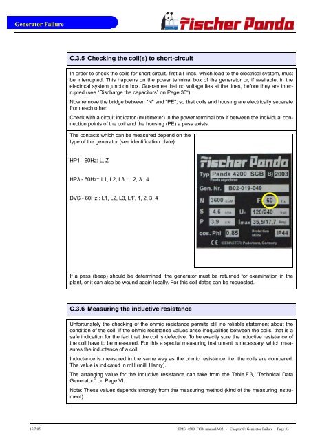
The contacts which can be measured depend on the<br />
type of the generator (see identification plate):<br />
HP1 - 60Hz: L, Z<br />
HP3 - 60Hz:: L1, L2, L3, 1, 2, 3 , 4<br />
DVS - 60Hz : L1, L2, L3, L1’, 1, 2, 3, 4<br />
If a pass (beep) should be determined, the generator must be returned for examination in the<br />
plant, or it can also be wound again locally. For this coil datas can be requested.<br />
C.3.6 Measuring the inductive resistance<br />
Unfortunately the checking of the ohmic resistance permits still no reliable statement about the<br />
condition of the coil. If the ohmic resistance values arise inequalities between the coils, that is a<br />
safe indication for the fact that the coil is defective. To be exactly sure the inductive resistance of<br />
the coil have to be measured. For this a special measuring instrument is necessary, which measures<br />
the inductance of a coil.<br />
Inductance is measured in the same way as the ohmic resistance, i.e. the coils are compared.<br />
The value is indicated in mH (milli Henry).<br />
The arranging value for the inductive resistance can take from the Table F.3, “Technical Data<br />
Generator,” on Page VI.<br />
Note: These values depends strongly from the measuring method (kind of the measuring instrument)<br />
15.7.05 <strong>PMS</strong>_<strong>4500</strong>_<strong>FCB</strong>_manual.V02 - Chapter C: Generator Failure Page 33