PMS 4500 FCB Manual - Ysebaert
PMS 4500 FCB Manual - Ysebaert
PMS 4500 FCB Manual - Ysebaert

You also want an ePaper? Increase the reach of your titles
YUMPU automatically turns print PDFs into web optimized ePapers that Google loves.
Installation Instructions<br />
D.7.3<br />
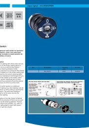
The speed sensor<br />
Speed sensor<br />
Installation of the speed sensor<br />
The speed sensor tip must have between<br />
0.3 to 0.8mm of clearance (air gap) from<br />
the gear tooth tips. In order to achieve this<br />
clearance: the speed sensor tip should be<br />
aligned with the tip of a gear tooth and<br />
screwed in until it touches the tip of the<br />
tooth. (ATTENTION! Ensure that when<br />
inserting the sensor, that the sensor tip<br />
is not screwed into the root of the gear<br />
tooth). The screw is subsequently turned<br />
anticlockwise by half a turn (0.3 to 0.8mm)<br />
and held by a counter nut.<br />
4<br />
1<br />
1. Speed sensor on threaded seat<br />
2. Engine Flywheel (with gear teeth)<br />
3. Generator housing<br />
4. Retention/tightening nut<br />
2<br />
3<br />
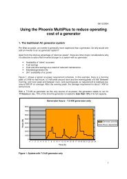
1<br />
1<br />
2 2<br />
1. Speed sensor on threaded seat<br />
2. Engine Flywheel (with gear teeth)<br />
D.7.4<br />
Electronic starter control unit<br />
If there is an automatic starting requirement<br />
and if the remote control panel is<br />
switched off, then this automatic starting<br />
requirement is ignored. Automatic starting<br />
is only possible if after switching on of<br />
the remote control panel the automatic<br />
starting requirement takes place.<br />
Page 56 <strong>PMS</strong>_<strong>4500</strong>_<strong>FCB</strong>_manual.V02 - Chapter D: Installation Instructions 15.7.05