PMS 4500 FCB Manual - Ysebaert
PMS 4500 FCB Manual - Ysebaert
PMS 4500 FCB Manual - Ysebaert

You also want an ePaper? Increase the reach of your titles
YUMPU automatically turns print PDFs into web optimized ePapers that Google loves.
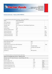
Installation Instructions<br />
D.8.4<br />
Booster electronic<br />
The booster electronic regulates the electrical voltage of the generator. It includes the number of<br />
revolutions of the engine.<br />
All control signals are processed on the measuring plate in the AC-Control box.<br />
Terminal designation<br />
Terminal Short term Specification<br />
1 L1 L1 of the measuring voltage and operating voltage<br />
2 N N of the measuring voltage and operating voltage<br />
3 J1.1 Port No. 1 of Jumper J1 (for 115V connect with port No. 4)<br />
4 J1.2 Port No. 2 of Jumper J1 (for 115V connect with port No. 3)<br />
5 J2.1 Port No. 1 of Jumper J2 (for 115V connect with port No. 6)<br />
6 J2.2 Port No. 2 of Jumper J2 (for 115V connect with port No. 5)<br />
7 SSR1+ Output No. 1 (positive) for Solid State Relay (SSR) No.1<br />
8 SSR1- Output No. 2 (negative) for Solid State Relay (SSR) No.1<br />
9 SSR2+ Output No. 1 (positive) for Solid State Relay (SSR) No.2<br />
10 SSR2- Output No. 2 (negative) for Solid State Relay (SSR) No.2<br />
15.7.05 <strong>PMS</strong>_<strong>4500</strong>_<strong>FCB</strong>_manual.V02 - Chapter D: Installation Instructions Page 61