Create successful ePaper yourself
Turn your PDF publications into a flip-book with our unique Google optimized e-Paper software.
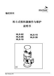
<strong>Hopper</strong> <strong>loader</strong><br />
METRO 0.5 to 1.5<br />
<strong>Operating</strong> <strong>Manual</strong><br />
CE<br />
11/2005 096/05<br />
279A-00.0.EN V1.1
3 Technical specifications<br />
Specifications METRO 0.5 to 1.5<br />
3.3 Specifications<br />
3.3.1 Dimensions of the hopper <strong>loader</strong>s<br />
Fig. 3.2 – Dimensions of the hopper <strong>loader</strong>s<br />
Size METRO H** 0.5 METRO H** 1.5 METRO M** 0.5 METRO M** 1.5<br />
A<br />
456 mm<br />
549 mm<br />
450 mm<br />
543 mm<br />
(17.8 inch)<br />
(21.4 inch)<br />
(17.5 inch)<br />
(21.1 inch)<br />
B<br />
302 mm<br />
395 mm<br />
296 mm<br />
389 mm<br />
(11.8 inch)<br />
(15.4 inch)<br />
(11.5 inch)<br />
(15.1 inch)<br />
12 Edition: November 2005
METRO 0.5 to 1.5<br />
Technical specifications 3<br />
Specifications<br />
3.3.2 Dimensions of the hopper <strong>loader</strong>s<br />
Fig. 3.3 – Dimensions of the hopper <strong>loader</strong>s<br />
Size METRO HC/J* METRO HP* METRO MC/J* METRO MP*<br />
C<br />
102 mm<br />
(4.0 inch)<br />
D<br />
253 mm<br />
232 mm<br />
242 mm<br />
221 mm<br />
(9.8 inch)<br />
(9.0 inch)<br />
(9.4 inch)<br />
(8.6 inch)<br />
E<br />
317 mm<br />
317 mm<br />
295 mm<br />
306 mm<br />
(12.4 inch)<br />
(12.4 inch)<br />
(11.5 inch)<br />
(11.9 inch)<br />
Edition: November 2005 13
3 Technical specifications<br />
Specifications METRO 0.5 to 1.5<br />
3.3.3 Dimensions (connections) - hopper <strong>loader</strong>s<br />
Fig. 3.4 – Dimensions of the hopper <strong>loader</strong>s<br />
[F] Ø material inlet<br />
[G] Ø vacuum pipe<br />
Option Size METRO 0.5 METRO 1.5<br />
1<br />
2<br />
F<br />
G<br />
F<br />
G<br />
38 mm (1.5 inch)<br />
45 mm (1.7 inch)<br />
45 mm (1.7 inch)<br />
45 mm (1.7 inch)<br />
3.3.4 Dimensions of flange METRO H/M**<br />
METRO H**<br />
METRO M**<br />
Fig. 3.5 – Dimensions of flange METRO H/M**<br />
Size METRO H** 0.5 METRO H** 1.5 METRO M** 0.5 METRO M** 1.5<br />
A 215 mm (8.3 inch) 100 mm (3.9 inch)<br />
B 7mm (0.3inch 9mm (3.5inch)<br />
C 171 mm (6.7 inch) 47 mm (1.8 inch)<br />
D 195 mm (7.6 inch) 75 mm (2.9 inch)<br />
14 Edition: November 2005
METRO 0.5 to 1.5<br />
Technical specifications 3<br />
Specifications<br />
3.3.5 Weight and other data<br />
METRO H** 0.5 METRO H** 1.5 METRO M** 0.5 METRO M** 1.5<br />
Weight<br />
4.5 kg<br />
(9.9 lbs)<br />
5.0 kg<br />
(11.0 lbs)<br />
2.9 kg<br />
(6.4 lbs)<br />
Capacity<br />
0.5 l<br />
1.5 l<br />
0.5 l<br />
(0.02 cft) (0.05 cft) (0.02 cft)<br />
Mesh size of filter 500µ<br />
3.4 kg<br />
(7.5 lbs)<br />
1.5 l<br />
(0.05 cft)<br />
3.3.6 Electrics and pneumatics<br />
METRO 0.5 METRO 1.5<br />
Control voltage<br />
P-<strong>loader</strong>/C-<strong>loader</strong><br />
Control voltage<br />
J-<strong>loader</strong><br />
Compressed air<br />
connection<br />
24 V DC<br />
120 V AC<br />
4–6 bar (60–90 psi)<br />
Edition: November 2005 15
METRO 0.5 to 1.5<br />
Transport and setup 4<br />
Mounting hopper <strong>loader</strong><br />
4 Transport and setup<br />
4.1 Mounting hopper <strong>loader</strong><br />
Discharge module<br />
Machine module<br />
Fig. 4.1 – Attaching hopper <strong>loader</strong><br />
[1] Hexagon-headed screw<br />
[2] Washer<br />
[3] Flange seal<br />
[4] Hexagon nut self-locking<br />
[5] Spring washer<br />
[6] Hexagonal nut<br />
Position the flange seal [3] on the machine or drying bin.<br />
Position the hopper <strong>loader</strong> on the machine or drying bin.<br />
Connect the hopper <strong>loader</strong> tightly to the machine or drying bin as shown above. Note the different<br />
design of discharge and machine module.<br />
Edition: November 2005 17
4 Transport and setup<br />
Connections METRO 0.5 to 1.5<br />
4.2 Connections<br />
4.2.1 Compressed air connection<br />
Connect the air hose (PU tube Ø 4x1 mm (Ø 0.16x0.04")) to the compressed air connection on the<br />
unit [1].<br />
The operating pressure must be 0.4–0.6 MPa (4–6 bar (60–90 psi)).<br />
Fig. 4.2 – Connecting compressed air METRO *C/J*<br />
[1] Compressed air connection<br />
Fig. 4.3 – Connecting compressed air METRO *P*<br />
[1] Compressed air connection<br />
The operating pressure must not fall below 0.4 MPa (4 bar (60 psi)).<br />
Note<br />
18 Edition: November 2005
METRO 0.5 to 1.5<br />
Transport and setup 4<br />
Connections<br />
4.2.2 Fastening material/vacuum hose<br />
MATERIAL DAMAGE!<br />
CAUTION!<br />
Incorrectly attached material tubes cause transport problems and damage to the hopper<br />
<strong>loader</strong>.<br />
Lay out material/vacuum hose to the hopper <strong>loader</strong> with a sufficiently wide curve.<br />
Ground the hose.<br />
Fig. 4.4 – Flow direction<br />
[1] Flow direction with PU tubes<br />
Note the flow direction (PU tubes only, optional), (see figure 4.4). Incorrect installation direction<br />
may influence the transport output.<br />
Fig. 4.5 – Grounding material/vacuum hose<br />
[1] Wire spiral<br />
Remove the wire spiral [1] from the tube and bend it inwards to make it contact the hopper <strong>loader</strong>.<br />
Slide the material/vacuum hose on to the connection on the hopper <strong>loader</strong> and fasten the hose<br />
with a suitable hose band clip (see Figure 4.5).<br />
Edition: November 2005 19
4 Transport and setup<br />
Connections METRO 0.5 to 1.5<br />
4.2.3 Electrical connection<br />
Connecting the control cable<br />
CAUTION!<br />
MATERIAL DAMAGE!<br />
Radiant heat and hot surfaces may damage the controller cable.<br />
Lay out the controller cable so it will not be damaged by the heat of downstream<br />
units (hot surfaces or radiant heat)!<br />
Fig. 4.6 – Connecting control cable METRO *C/J*<br />
[1] Control cable connection<br />
Fig. 4.7 – Connecting control cable METRO *P*<br />
[1] Control cable connection<br />
The electrical power is supplied from the controller via the controller cable (see figure 4.64.7).<br />
20 Edition: November 2005
METRO 0.5 to 1.5<br />
Structure and function 5<br />
Function<br />
5 Structure and function<br />
Fig. 5.1 – Layout of the hopper <strong>loader</strong>s<br />
[1] Unit cover<br />
[2] Implosion module<br />
[3] Material inlet module<br />
[4] Multifunction panel METRO *C/J*<br />
[5] Glass/stainless steel<br />
[6] Material discharge module (bin <strong>loader</strong>)<br />
[7] Proximity switch (METRO H** only)<br />
[8] Multifunction panel METRO *P*<br />
[9] Material discharge module (machine hopper<br />
<strong>loader</strong>)<br />
[10] Demand probe (METRO M** only)<br />
5.1 Function<br />
In a hopper <strong>loader</strong> system with METRO H** and/or METRO M** hopper <strong>loader</strong>s one central Motan<br />
controller controls all units in the system.<br />
The different hopper <strong>loader</strong>s report a material requirement to the relevant controller and are then<br />
processed in succession.<br />
METRO H**: Material required via the Proximity switch if the discharge flap is closed<br />
METRO M**: Material required via the demand probe if the granulate no longer covers the demand<br />
probe.<br />
If material is required by one or more hopper <strong>loader</strong>s, the blower station starts and generates<br />
underpressure in the vacuum line. The bypass valve on the filter closes and simultaneously open the<br />
vacuum valve in the hopper <strong>loader</strong>. An underpressure forms in the vacuum line and continues<br />
through the hopper <strong>loader</strong> to the material line through to the suction point.<br />
Edition: November 2005 21
5 Structure and function<br />
Function METRO 0.5 to 1.5<br />
Fig. 5.2 – Functional diagram of the METRO H 0.5/1.5 hopper <strong>loader</strong><br />
[1] Vacuum line<br />
[2] Implosion valve open<br />
[3] Material tube<br />
[4] Discharge flap<br />
[5] Inlet flap open<br />
[6] Vacuum valve open<br />
[7] Inlet flap closed<br />
[8] Vacuum valve closed<br />
[9] Proximity switch<br />
The aspirated air forms a mixture of air and granulate in the material line. The granulate falls down<br />
by gravity when it enters the hopper <strong>loader</strong>. The dust particles in the granulate pass through the<br />
screen filter and are removed by the central filter. This removes dust from the granulate at the same<br />
time.<br />
Depending on the specified conveying time the vacuum valve closes to form an airtight seal. Because<br />
of the underpressure in the hopper <strong>loader</strong> the implosion valve now opens suddenly for a short time.<br />
The implosion cleans the screen filter after every loading cycle.<br />
METRO H**: as a result of the implosion the underpressure in the hopper <strong>loader</strong> collapses and the<br />
weight of the granulate opens the discharge flap. The material flows into the machine bin.<br />
The vacuum valve in the hopper <strong>loader</strong> opens at the next demand. The loading cycle starts.<br />
Only one hopper <strong>loader</strong> at a time can be filled on a blower line.<br />
If all hopper <strong>loader</strong>s are full and no material required is pending at the controller, the bypass valve on<br />
the filter opens, the blower aspirates fresh air and switches off after a specified run-on time. This<br />
reduces the load on the blower station.<br />
If a hopper <strong>loader</strong> reports material required again to the controller, the blower station is switched on<br />
and a new loading cycle starts.<br />
22 Edition: November 2005
9 Maintenance and repair<br />
Maintenance and cleaning METRO 0.5 to 1.5<br />
Fig. 9.2 – Screen filter<br />
[1] Screen filter<br />
[2] Filter fastener rod<br />
Prepare the hopper <strong>loader</strong> for maintenance (see "Maintenance and repair" on Page 32).<br />
Open the spring clips on the top of the unit.<br />
Open the cover.<br />
Remove the screen filter.<br />
Tap the screen filter to clean it and clean the screen filter with a vacuum cleaner.<br />
Check its condition and if necessary replace the screen filter.<br />
Structure<br />
Fig. 9.3 – Replace screen filter<br />
[1] Screen filter<br />
[2] Fastener ring<br />
Insert the screen filter so the screen filter seal contacts the fastener ring [2].<br />
Check that the screen filter [1] is correctly positioned, i.e. the rods of the filter fastener (see figure<br />
9.2) are not in the vicinity of the vacuum valve.<br />
MALFUNCTION!<br />
CAUTION!<br />
The required vacuum may not be generated if the rods of the filter fastener project<br />
above the hopper housing.<br />
Never force the cover closed.<br />
Make sure that the screen filter is precisely positioned and that the rods do not<br />
project above the hopper housing.<br />
Close the cover and lock it with the spring clips.<br />
34 Edition: November 2005
METRO 0.5 to 1.5<br />
Maintenance and repair 9<br />
Maintenance and cleaning<br />
Note<br />
The screen filter clogs up faster when regrind material is transported.<br />
Reduce cleaning intervals appropriately.<br />
9.4.2 Check inlet flap<br />
Fig. 9.4 – Check inlet flap<br />
[1] Check inlet flap<br />
Prepare the hopper <strong>loader</strong> for maintenance (see "Before starting work" on Page 32).<br />
Remove the screen filter (see "Clean screen filter." on Page 33).<br />
Check the inlet flap [1] for wear (see arrows in the magnified view).<br />
Edition: November 2005 35
9 Maintenance and repair<br />
Repair work METRO 0.5 to 1.5<br />
9.5 Repair work<br />
9.5.1 Disassemble METRO 0.5-1 to 1.5-1 hopper <strong>loader</strong> into its modules<br />
6<br />
A<br />
B<br />
Fig. 9.5 – METRO H** hopper <strong>loader</strong>s<br />
[A] METRO HC/J*<br />
[B] METRO HP*<br />
[1] Profile clamp<br />
[2] Ground terminal<br />
[3] Seal<br />
[4] Screw<br />
[5] Multifunction panel<br />
[6] Ground (glass units only)<br />
Separating modules<br />
Material damage!<br />
Parts which fall into the unit may cause operational faults.<br />
CAUTION!<br />
Make sure that no parts fall into the unit.<br />
Cover the opening of the machine and bin.<br />
Prepare the hopper <strong>loader</strong> for maintenance (see "Before starting work" on Page 32).<br />
To separate the module, slacken the screw [4] and remove the profile clamp [1] (also the ground<br />
for glass units [6]).<br />
Disengage the module.<br />
Remove the seal [3].<br />
Remove the ground clamp [2].<br />
36 Edition: November 2005
METRO 0.5 to 1.5<br />
Maintenance and repair 9<br />
Repair work<br />
Assembling modules<br />
Attach the ground clamp [2].<br />
Place the seal [3] on the contact surface of the bottom module.<br />
Position the module.<br />
Position the profile clamp [1] and fasten the clamp with screw [4] (also the ground for glass units<br />
[6]).<br />
9.5.2 Replacing vacuum valve<br />
Material damage!<br />
Parts which fall into the unit may cause operational faults.<br />
CAUTION!<br />
Make sure that no parts fall into the unit.<br />
Cover the opening of the machine and bin.<br />
Fig. 9.6 – Vacuum valve<br />
[1] Hexagonal nut<br />
[2] Implosion valve<br />
[3] Spacer rod<br />
[4] Contact surface of the spacer rod<br />
[5] Sealing disk<br />
[6] Vacuum seal<br />
[7] Hexagon-headed screw M6<br />
[8] Spring<br />
[9] Piston rod<br />
[10] Contact surface of the piston rod<br />
[11] Pneumatic cylinder<br />
Removal<br />
Prepare the hopper <strong>loader</strong> for maintenance (see "Before starting work" on Page 32).<br />
Edition: November 2005 37
9 Maintenance and repair<br />
Adjusting proximity switch (METRO H** only) METRO 0.5 to 1.5<br />
Note<br />
Make sure that no parts fall into the unit.<br />
Cover the opening of the machine and bin.<br />
Unscrew the M6 hexagon-headed screw [7]. Using a forked wrench (WAF 9), push against the<br />
contact surface of the piston rod [4].<br />
Press the spacer rod [3] back manually and pull the sealing disk [5] out.<br />
Remove the spring [8].<br />
Slacken the hexagon nut [1] on the pneumatic cylinder [11].<br />
Unscrew the pneumatic cylinder [11] and remove the implosion valve [2].<br />
Loosen the spacer rod with forked wrench (WAF 9). Using a forked wrench (WAF 9), push against<br />
the contact surface of the piston rod [10].<br />
Unscrew the spacer rod [3].<br />
Installation<br />
Assemble in reverse order.<br />
Make sure that the sealing disk [5] contacts the seal [6] after assembly.<br />
Lock the thread of the piston rod [9] with Loctite 270 and the hexagon-headed screw [7] with Loctite<br />
242.<br />
9.6 Adjusting proximity switch (METRO H** only)<br />
2<br />
1<br />
Fig. 9.7 – Adjusting proximity switch<br />
[1] Proximity switch<br />
[2] Hexagon nuts<br />
Prepare the hopper <strong>loader</strong> for maintenance (see "Before starting work" on Page 32).<br />
Close the discharge flap.<br />
Set the clearance as shown in the diagram 9.7.<br />
Lock the proximity switch [1] with the hexagon nuts [2].<br />
38 Edition: November 2005
METRO 0.5 to 1.5<br />
Maintenance and repair 9<br />
Adjusting discharge flap (METRO H** only)<br />
9.7 Adjusting discharge flap (METRO H** only)<br />
Fig. 9.8 – Positioning weight<br />
[1] Weight<br />
Slide the weight on to the tension pin and fix the weight.<br />
Installation position: see diagram 9.8.<br />
Tighten the set screw and lock it with Loctite 242.<br />
Fig. 9.9 – Adjusting discharge flap<br />
[1] Spring-loaded thrust pad<br />
[2] Discharge flap<br />
[3] Discharge<br />
Screw the spring-loaded thrust pad [1] (see figure 9.9) up until the gap between the discharge [3]<br />
and the discharge flap [2] is<br />
5-8 mm.<br />
Note<br />
The air gap at the discharge flap ensures that particles of granulate on the discharge<br />
flap are sucked in by the vacuum at the start of transport.<br />
The discharge flap is pulled up by the vacuum and forms an airtight seal.<br />
Edition: November 2005 39
METRO 0.5 to 1.5<br />
Option 11<br />
Implosion filter option<br />
11 Option<br />
11.1 Implosion filter option<br />
The implosion filter prevents the entry of dust into the unit and prevents the release of dust into the<br />
environment.<br />
11.1.1 Intervals for inspections, maintenance and cleaning work<br />
Monthly<br />
Component Activity Target value/Meaning Qualification<br />
Implosion filter for damage and clean See "Maintenance work" on<br />
Page 43<br />
Seal for damage See "Maintenance work" on<br />
Page 43<br />
Operator<br />
Operator<br />
11.1.2 Maintenance work<br />
Fig. 11.1 – Implosion filter<br />
[1] Nut<br />
[2] Sealing ring<br />
[3] Cover plate of implosion filter<br />
[4] Implosion filter<br />
[5] Spacer<br />
[6] Seal<br />
[7] Cable passage<br />
[8] Plug connector<br />
Prepare the hopper <strong>loader</strong> for maintenance (see "Before starting work" on Page 32).<br />
Check the implosion filter (visual check) for damage.<br />
Check the cable passage gland for damage.<br />
Check the seal for damage.<br />
Edition: November 2005 43
11 Option<br />
Implosion filter option METRO 0.5 to 1.5<br />
11.1.3 Maintenance<br />
Fig. 11.2 – Implosion filter<br />
[1] Nut<br />
[2] Sealing ring<br />
[3] Cover plate of implosion filter<br />
[4] Implosion filter<br />
[5] Spacer<br />
[6] Seal<br />
[7] Cable passage<br />
[8] Plug connector<br />
Removing implosion filter<br />
Prepare the hopper <strong>loader</strong> for maintenance (see "Before starting work" on Page 32).<br />
Label the PU tubes to the implosion filter and undo the PU tubes.<br />
Remove the plug connector [8].<br />
Slacken the nut [1] and remove the sealing ring [2].<br />
Remove the cover plate of the implosion filter [3] and pull the implosion filter [4] off.<br />
Remove the spacer [5] and the seal [6].<br />
Installing implosion filter<br />
Assemble in reverse order.<br />
Make sure that the PU tubes are correctly installed.<br />
44 Edition: November 2005
METRO 0.5 to 1.5<br />
Option 11<br />
Implosion filter option<br />
11.1.4 Spare parts<br />
Spare parts list<br />
Item Unit Designation Article no. Remarks<br />
1 1 Bend 4119050<br />
2 2 Screw-plug connector straight M5 4110160<br />
3 rm PU tube Ø 4x1 mm (Ø 0.16x0.04") 4037050 Calibrated<br />
4 1 Pressure connection for implosion filter 4119040<br />
5 1 Implosion filter seal 4119060<br />
6 1 Implosion filter spacer 4119070<br />
7 1 Implosion filter 4119100<br />
8 1 Cover plate of implosion filter 4119110<br />
9 1 Sealing ring 4044270<br />
10 1 Nut 4072970<br />
11 1 Plug connector 4070220<br />
12 1 Cable passage 1168150<br />
Edition: November 2005 45
METRO 0.5 to 1.5<br />
Appendix 12<br />
METRO 0.5 to 1.5<br />
12 Appendix<br />
12.1 METRO 0.5 to 1.5<br />
Spare parts list<br />
Item Unit Designation Article no. Remarks<br />
1 1 Implosion module complete 5084700<br />
2 1 Inlet flap 4114910<br />
3 1 Glass module 4117020 available for 1.5 l<br />
1 Steel module 4118000<br />
only<br />
4 1 Proximity switch 24 V 4038130<br />
1 Proximity switch 120 V 25008512<br />
5 1 Discharge module complete 5084650<br />
6 1 Ground terminal 4117720 METRO 0.5<br />
2 METRO 1.5<br />
7 1 U-profile seal 4115040 METRO 0.5<br />
2 METRO 1.5<br />
8 1 Profile clamp 4114930 METRO 0.5<br />
2 METRO 1.5<br />
9 1 Machine module 4115030<br />
10 1 Demand probe 24 V 4102410 for material<br />
1 Demand probe 120 V<br />
up to 80 °C<br />
Edition: November 2005 47
12 Appendix<br />
METRO 0.5 to 1.5 METRO 0.5 to 1.5<br />
Spare parts list<br />
Item Unit Designation Article no. Remarks<br />
11 1 Screen filter 500 µ 4115370<br />
1 Screen filter 1200 µ 4158730<br />
12 1 Filter fastener 4115380<br />
13 2 Cap 4158590<br />
48 Edition: November 2005
METRO 0.5 to 1.5<br />
Appendix 12<br />
METRO 0.5 to 1.5<br />
12.1.1 Implosion module METRO 0.5 to 1.5<br />
Spare parts list<br />
Item Unit Designation Article no. Remarks<br />
1 1 Cover 4115450<br />
2 1 Warning sign 4103380<br />
3 2 Countersunk screw M4 1237810<br />
4 1 Edge protector 1192960<br />
5 1 Implosion module 4115720<br />
7 2 O-ring 1110660<br />
6 1 Axis at cover 4115470<br />
8 4 Hexagon nut M4 1238200<br />
9 1 Vacuum seal i<br />
4158100<br />
10 1 Hexagon-headed screw M6 ii<br />
1228900<br />
11 1 Vacuum sealing disk 4114870<br />
12 1 Spring 4115580<br />
13 1 Spacer rod to implosion iii<br />
4114430<br />
14 1 Implosion mechanical components complete 4158400<br />
15 1 Pneumatic cylinder 4158440<br />
16 2 L-connector screw retainer 4158630<br />
17 2 Spring clip 4158310<br />
18 1 Seal for cover 4115460<br />
i Secured with Loctite 406<br />
ii Secured with Loctite 242<br />
iii Secured with Loctite 270<br />
Edition: November 2005 49
12 Appendix<br />
METRO 0.5 to 1.5 METRO 0.5 to 1.5<br />
12.1.2 Discharge module METRO 0.5 to 1.5<br />
Spare parts list<br />
Item Unit Designation Article no. Remarks<br />
1 1 Discharge module welded 4117730<br />
2 2 Silencer 4063970<br />
3 2 Sealing ring 4044670<br />
4 1 Flap shaft 4116960<br />
5 1 Bearing plate 4083770<br />
6 1 Weight 4070150<br />
7 1 Thread pin M5 i<br />
4063030<br />
8 1 Thrust pad M8 spring-loaded 4069230<br />
9 2 Hexagon nut M8 3034630<br />
10 2 Philips-head screw M4 4050900<br />
11 2 Spring washer A4 1210880<br />
12 1 Screw M6 i 4083720 Verbus Ripp<br />
13 1 Fastener t= 1.5 4117310<br />
14 2 Hexagon nut M6 with clamp section i 1902350 ISO 7042<br />
15 2 Lens flange flat-head screw M6 4073190<br />
16 1 Flap t=0.5 4117330<br />
17 1 O-ring 4078360<br />
i Secured with Loctite 242<br />
50 Edition: November 2005
METRO 0.5 to 1.5<br />
Appendix 12<br />
Multifunction panel METRO *C/J/P*<br />
12.2 Multifunction panel METRO *C/J/P*<br />
Spare parts list<br />
Item Unit Designation Article no. Remarks<br />
A 1 Multifunction panel METRO C basic 5062440 See page 12-52<br />
B 1 Multifunction panel METRO J 5069500 See page 12-53<br />
C 1 Multifunction panel METRO P 5086070 See page 12-54<br />
Edition: November 2005 51
12 Appendix<br />
Multifunction panel METRO *C/J/P* METRO 0.5 to 1.5<br />
12.2.1 Multifunction panel METRO C basic<br />
Spare parts list<br />
Item Unit Designation Article no. Remarks<br />
A 1 Multifunction panel METRO C basic 5062440 complete<br />
1 1 Controller METRO C 4158010<br />
2 1 Valve cable 4158600<br />
3 1 MFP component carrier 4118010<br />
4 6 Philips-head screw M4 4050900<br />
5 1 L-connector screw retainer 4158630<br />
6 1 Silencer 4063970<br />
7 2 Philips-head screw M4 1206930<br />
8 1 4/2 directional control valve 4158580<br />
52 Edition: November 2005
12 Appendix<br />
Multifunction panel METRO *C/J/P* METRO 0.5 to 1.5<br />
12.2.3 Multifunction panel METRO P<br />
Spare parts list<br />
Item Unit Designation Article no. Remarks<br />
C 1 Multifunction panel METRO P 5086070 complete<br />
1 2 Philips-head screw M3 1206260<br />
2 1 Control plug 5074240<br />
3 1 Valve cable 4158600<br />
4 1 Fastener P-<strong>loader</strong> 4118010<br />
5 2 Philips-head screw M4 4050900<br />
6 1 L-connector screw retainer 4158630<br />
7 1 Silencer 4063970<br />
8 2 Philips-head screw M4 1206930<br />
9 1 4/2 directional control valve 4158580<br />
54 Edition: November 2005
METRO 0.5 to 1.5<br />
Appendix 12<br />
Pneumatics diagram<br />
12.3 Pneumatics diagram<br />
12.3.1 METRO 0.5 to 1.5<br />
[1] Vacuum valve<br />
Edition: November 2005 55
A<br />
B<br />
C<br />
D<br />
E<br />
2<br />
A1<br />
+ZSW<br />
PE + 24V M VACV<br />
PE<br />
1<br />
2<br />
3<br />
W5F1<br />
PVC Steuerleitung<br />
12x1mmý<br />
GNYE 1 2 3<br />
-XS PE 1 2 3<br />
+KK<br />
-X41 3PE<br />
2<br />
1<br />
W5Y1<br />
H05VV-F/F<br />
3x0,75<br />
BU<br />
BN<br />
1<br />
2<br />
-5Y1<br />
F 2 1<br />
Vakuum Ventil<br />
Vacuum Valve<br />
Datum<br />
18.10.2005<br />
Bearb.<br />
EKA<br />
Gepr.<br />
nderung Datum Name<br />
Norm<br />
1<br />
2<br />
3<br />
GNYE<br />
1<br />
1<br />
PE<br />
2<br />
2<br />
-5H1 -5H2<br />
+F16<br />
Vakuum<br />
Vacuum<br />
Niveau<br />
Level<br />
Projekt:<br />
METRO C basic<br />
SPS (PLC)/SELVAC<br />
27.11.2001<br />
3<br />
4<br />
5<br />
6<br />
7<br />
ANFO<br />
ONLP ONTS<br />
NIBE<br />
ZWVV<br />
RES RES<br />
6<br />
5<br />
7<br />
4<br />
8<br />
9<br />
10<br />
6<br />
5 7<br />
4<br />
8<br />
9 10<br />
6<br />
5<br />
7<br />
4<br />
8<br />
9<br />
10<br />
6 4 5<br />
7PE<br />
10 8 9<br />
12 11<br />
14 13 15PE<br />
W5B1<br />
SENSOR<br />
3x0,34<br />
BK BN<br />
W5B2<br />
SENSOR<br />
4x0,34<br />
BU<br />
W5Y2<br />
H05VV-F/F<br />
3x0,75<br />
BK BN BU<br />
BU BN<br />
GNYE<br />
BN<br />
BU<br />
+F<br />
H-LOADER<br />
-5B1<br />
1<br />
2<br />
3<br />
4<br />
BN<br />
BU<br />
-5B2<br />
1<br />
2<br />
BK<br />
BK<br />
*<br />
**<br />
BN BU<br />
+F<br />
Ï<br />
-5Y2<br />
-5H3 -5S1<br />
**<br />
WH<br />
+F<br />
M-LOADER<br />
-5B1<br />
+F16<br />
* Option 1<br />
** Option 2<br />
Anforderung Material<br />
Demand Material<br />
Ein Aus Alarm Niveau Beh„lter<br />
Zwangsverschluss<br />
On Off Alarm Level <strong>Hopper</strong><br />
Operated flap<br />
Vers.<br />
Motan GmbH<br />
Max-Eyth-Weg 42<br />
+ F1<br />
Kommission: Zeichng.Nr.:<br />
Urspr. Ers. f. Ers. d.<br />
88316 Isny Steuerung<br />
Control (unit)<br />
=<br />
F1<br />
REG<br />
Convey 280A-90.0.00<br />
4<br />
5<br />
6<br />
7<br />
8<br />
RES<br />
11<br />
11<br />
11<br />
16PE<br />
+KAUE/1<br />
1.0<br />
Blatt<br />
Gr.:<br />
8<br />
5<br />
A<br />
B<br />
C<br />
D<br />
E<br />
F
A<br />
B<br />
1<br />
C<br />
F 2<br />
D<br />
E<br />
nderung Datum Name<br />
1<br />
Datum<br />
Bearb.<br />
Gepr.<br />
Norm<br />
2<br />
10.05.2005<br />
EKA<br />
2<br />
3<br />
4<br />
5<br />
6<br />
7<br />
8<br />
=ZSW<br />
F”rdersteuerung<br />
Conveying control<br />
L+ M<br />
PE<br />
VAKUUM<br />
ANFO<br />
WF1<br />
PVC Steuerleitung<br />
5x1mmý<br />
1 2<br />
GNYE 3<br />
4<br />
-11XS1.1<br />
1 2<br />
Ï<br />
3<br />
4<br />
-11XS1<br />
1<br />
2<br />
Ï<br />
3<br />
4<br />
1,0 mmý<br />
GNYE<br />
H05V-K<br />
+EX<br />
-PE<br />
Ï<br />
WY1<br />
PVC Steuerleitung<br />
1m<br />
3x1mmý<br />
2 GNYE 1<br />
+F<br />
H-LOADER<br />
-11B1<br />
BN<br />
BU<br />
Ï<br />
-11Y1<br />
1<br />
2<br />
BK<br />
5 VA<br />
BN<br />
BU<br />
+F<br />
M-LOADER<br />
-11B1<br />
WH<br />
Anforderung<br />
Demand<br />
Vakuumventil<br />
Vaccum valve<br />
+KAUE/1<br />
Projekt:<br />
Vers.<br />
METRO P-LOADER<br />
Motan GmbH Steuerung<br />
= F1<br />
Max-Eyth-Weg 42 Control (unit)<br />
+ F1<br />
Kommission: Zeichng.Nr.:<br />
Blatt<br />
88316 Isny<br />
Urspr. Ers. f. Ers. d.<br />
29.10.2002<br />
REG<br />
Convey 280G-90.0.00<br />
Gr.:<br />
3<br />
4<br />
5<br />
6<br />
7<br />
8<br />
11<br />
A<br />
B<br />
C<br />
D<br />
E<br />
F
A<br />
B<br />
C<br />
D<br />
E<br />
2<br />
3<br />
4<br />
5<br />
6<br />
7<br />
8<br />
A1<br />
+ZSW<br />
PE<br />
Sensor Ein VACV<br />
sensor on<br />
120VAC<br />
ANFO<br />
ZWV<br />
DUOM<br />
N<br />
PE<br />
5<br />
1<br />
4<br />
6<br />
2<br />
3<br />
W5F1<br />
PVC Steuerleitung<br />
7xAWG20<br />
GNYE 5<br />
1 4<br />
6<br />
2<br />
3<br />
GN<br />
+KK13<br />
-XS1 PE<br />
BN<br />
5<br />
RD<br />
1<br />
WH<br />
4<br />
BU<br />
6<br />
OG<br />
2<br />
BK<br />
3<br />
+KK<br />
W5XS1<br />
JZ-603<br />
0,2m<br />
7xAWG18<br />
GNYE<br />
+KK13<br />
-5S1<br />
5<br />
1<br />
1a<br />
1<br />
4<br />
6<br />
2<br />
3<br />
AWG16<br />
BK<br />
H07-V2K<br />
-X01 1<br />
11 1PE<br />
2 3 2PE<br />
4<br />
12 2PE<br />
5<br />
13 3PE<br />
3PE<br />
F 2 1<br />
W5Y1<br />
PVC Steuerleitung<br />
3xAWG20<br />
1<br />
RD<br />
2<br />
WH<br />
GNYE<br />
GN<br />
W5B1<br />
PVC Steuerleitung<br />
3xAWG20<br />
1<br />
BN<br />
2<br />
BU<br />
GNYE<br />
GN<br />
W5Y2<br />
PVC Steuerleitung<br />
3xAWG20<br />
1<br />
RD<br />
2<br />
WH<br />
GNYE<br />
GN<br />
W5Y3<br />
PVC Steuerleitung<br />
3xAWG20<br />
+KK13<br />
-XS2 1 1<br />
RD<br />
2<br />
2<br />
WH<br />
PE<br />
GNYE<br />
GN<br />
3<br />
AWG16<br />
0,25m<br />
GNYE<br />
-5Y1<br />
1<br />
2<br />
PE<br />
+F<br />
-5B1<br />
1<br />
2<br />
PE<br />
-5Y2<br />
1<br />
2<br />
PE<br />
-5Y3<br />
1<br />
2<br />
PE<br />
H07-V2K<br />
*<br />
Alle Litzen sind<br />
als Multinorm Einzeladern<br />
UL-CSA-HAR auszufhren!<br />
+F<br />
Ï<br />
Ringkabelschuh M5<br />
Vakuum Ventil<br />
Vacuum Valve<br />
Anforderung Material<br />
Demand Material<br />
Zwangsverschluss<br />
operated flap<br />
DUOMIXVENTIL<br />
Proportioning Valve<br />
* Option<br />
+KAUE/1<br />
nderung Datum Name<br />
Datum<br />
Bearb.<br />
Gepr.<br />
Norm<br />
03.11.2005<br />
EKA<br />
Projekt:<br />
Vers.<br />
METRO J LOADER<br />
Motan GmbH Steuerung<br />
= F1<br />
Max-Eyth-Weg 42 Control (unit)<br />
+ F1<br />
Kommission: Zeichng.Nr.:<br />
Blatt<br />
88316 Isny<br />
Urspr. 27.11.2001 Ers. f. Ers. d. REG<br />
Convey 280F-90.0.00<br />
Gr.:<br />
1.0<br />
1<br />
2<br />
3<br />
4<br />
5<br />
6<br />
7<br />
8<br />
5<br />
A<br />
B<br />
C<br />
D<br />
E<br />
F