
You also want an ePaper? Increase the reach of your titles
YUMPU automatically turns print PDFs into web optimized ePapers that Google loves.
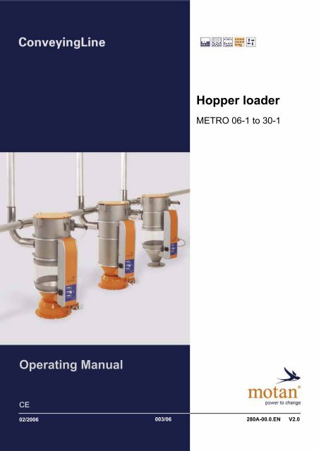
<strong>Hopper</strong> <strong>loader</strong>METRO 06-1 to 30-1<strong>Operating</strong> <strong>Manual</strong>CE02/2006 003/06280A-00.0.EN V2.0
METRO 06-1 to 30-1Transport and setup 4Mounting hopper <strong>loader</strong>4 Transport and setup4.1 Mounting hopper <strong>loader</strong>Discharge moduleMachine moduleFig. 4.1 – Attaching hopper <strong>loader</strong>[1] Hexagon-headed screw[2] Washer[3] Flange seal[4] Hexagon nut self-locking[5] Spring washer[6] Hexagonal nut Position the flange seal [3] on the machine or drying bin. Position the hopper <strong>loader</strong> on the machine or drying bin. Connect the hopper <strong>loader</strong> tightly to the machine or drying bin as shown above. Note the differentdesign of discharge and machine module.Edition: February 2006 17
METRO 06-1 to 30-1Transport and setup 4Connections4.2.2 Fastening material/vacuum hoseMATERIAL DAMAGE!CAUTION!Incorrectly attached material/vacuum hoses cause transport problems and damage tothe hopper <strong>loader</strong>. Lay out material/vacuum hose to the hopper <strong>loader</strong> with a sufficiently wide curve. Ground the hose.Fig. 4.4 – Flow direction[1] Flow direction with PU tubes Note the flow direction (PU tubes only, optional), (see figure 4.4). Incorrect installation directionmay influence the transport output.Fig. 4.5 – Ground material tube[1] Wire spiral Remove the wire spiral [1] from the tube and bend it inwards to make it contact the hopper <strong>loader</strong>. Slide the material/vacuum hose on to the connection on the hopper <strong>loader</strong> and fasten the hosewith a suitable hose band clip (see Figure 4.5).Edition: February 2006 19
4 Transport and setupConnections METRO 06-1 to 30-14.2.3 Electrical connectionConnecting the control cableCAUTION!MATERIAL DAMAGE!Radiant heat and hot surfaces may damage the controller cable. Lay out the controller cable so it will not be damaged by the heat of downstreamunits (hot surfaces or radiant heat)!Fig. 4.6 – Connecting control cable METRO *C/J*[1] Control cable connectionFig. 4.7 – Connecting control cable METRO *P*[1] Control cable connectionThe electrical power is supplied from the controller via the controller cable (see figure 4.64.7).20 Edition: February 2006
METRO 06-1 to 30-1Structure and function 5Function5 Structure and functionFig. 5.1 – Layout of the hopper <strong>loader</strong>s[1] Demand probe (METRO M** only)[2] Material discharge module (machine hopper<strong>loader</strong>)[3] Unit cover[4] Implosion module[5] Material inlet module[6] Multifunction panel METRO *C/J*[7] Glass/stainless steel[8] Material discharge module (bin <strong>loader</strong>)[9] Proximity switch (METRO H** only)[10] Multifunction panel METRO *P*5.1 FunctionIn a hopper <strong>loader</strong> system with METRO H** and/or METRO M** hopper <strong>loader</strong>s one central Motancontrollercontrols all units in the system.The different hopper <strong>loader</strong>s report a material requirement to the relevant controller and are thenprocessed in succession.METRO H**: Material required via the Proximity switch if the discharge flap is closedMETRO M**: Material required via the demand probe if the granulate no longer covers the demandprobe.If material is required by one or more hopper <strong>loader</strong>s, the blower station starts and generatesunderpressure in the vacuum line. The bypass valve on the filter closes and simultaneously open thevacuum valve in the hopper <strong>loader</strong>. An underpressure forms in the vacuum line and continuesthrough the hopper <strong>loader</strong> to the material line through to the suction point.Edition: February 2006 21
5 Structure and functionFunction METRO 06-1 to 30-1Fig. 5.2 – Functional diagram of the METRO H 06/10/15/30 hopper <strong>loader</strong>[1] Vacuum line[2] Implosion valve open[3] Material tube[4] Discharge flap[5] Inlet flap open[6] Vacuum valve open[7] Inlet flap closed[8] Vacuum valve closed[9] Proximity switchThe aspirated air forms a mixture of air and granulate in the material line. The granulate falls downby gravity when it enters the hopper <strong>loader</strong>. The dust particles in the granulate pass through thescreen filter and are removed by the central filter. This removes dust from the granulate at the sametime.Depending on the specified conveying time the vacuum valve closes to form an airtight seal. Becauseof the underpressure in the hopper <strong>loader</strong> the implosion valve now opens suddenly for a short time.The implosion cleans the screen filter after every loading cycle.METRO H**: as a result of the implosion the underpressure in the hopper <strong>loader</strong> collapses and theweight of the granulate opens the discharge flap. The material flows into the machine bin.The vacuum valve in the hopper <strong>loader</strong> opens at the next demand. The loading cycle starts.Only one hopper <strong>loader</strong> at a time can be filled on a blower line.If all hopper <strong>loader</strong>s are full and no material required is pending at the controller, the bypass valve onthe filter opens, the blower aspirates fresh air and switches off after a specified run-on time. Thisreduces the load on the blower station.If a hopper <strong>loader</strong> reports material required again to the controller, the blower station is switched onand a new loading cycle starts.22 Edition: February 2006
METRO 06-1 to 30-1Operation 7Settings7 Operation7.1 SettingsAll settings required for the function of the hopper <strong>loader</strong> are made at the central Motan controller(see corresponding operating manual).7.2 Material feed7.2.1 GeneralThe objective is to establish an even flow of material (air conveying) during suction. The air supply atthe suction point is adjusted for an even conveyor air flow.NoteThe air supply at the suction point must be readjusted every time the material changesbecause of the different flow properties of the various types of granulate.7.3 Operation7.3.1 CommissioningThe system must be installed by Motan technicians and transferred to the customer when it is readyfor operation.7.3.2 Continuous operationRequirements: Material line correctly connected Correct setting of the air supply at the suction point Electrical system correctly connected All values input or adjusted as specified in the operating manual of the controllerEdition: February 2006 25
7 OperationOperation METRO 06-1 to 30-17.3.3 Switching hopper <strong>loader</strong>s on and off (METRO *C* only)The hopper <strong>loader</strong> controller is fully wired at the factory. The electrical power is supplied from the controllervia the controller cable. For connection see "Electrical connection" on Page 20.[1] Vacuum light indicator[2] Illuminated On/Off button[3] Level light indicator (fill level)[4] Controller connectionFig. 7.1 – <strong>Hopper</strong> <strong>loader</strong> with METRO C multifunction panelFunctionsVacuum light indicator On: material is being conveyed. Off: no material is being conveyed.The material conveying depends on the Motan central controller.Material cannot be conveyed until the Motan central controller enables material conveying.Only one hopper <strong>loader</strong> at a time can be filled on the conveyor line.Illuminated On/Off buttonThe hopper <strong>loader</strong> controller can be switched on and off manually at every hopper <strong>loader</strong>. Press the illuminated button. When the illuminated button is on the hopper <strong>loader</strong> is on. Press the illuminated button. When the illuminated button is off the hopper <strong>loader</strong> is off. The illuminated button flashes and an alarm is displayed,(see "Troubleshooting" on Page 29).NoteThe hopper <strong>loader</strong>s are all switched on and off centrally at the On/Off switch at thecorresponding Motan central controller.It is not necessary to switch off the hopper <strong>loader</strong>s separately.If the hopper <strong>loader</strong>s are switched off individually, they remain switched off even afterthe Motan central controller has been switched off and then on again.Level light indicator (fill level) On: on empty signal.The minimum probe or the initiator require material. Off: on full signal.The minimum probe or the initiator do not require material.26 Edition: February 2006
METRO 06-1 to 30-1Operation 7Operation7.3.4 Switching demand probe on and off (METRO *J* only)The hopper <strong>loader</strong> controller is fully wired at the factory. The electrical power is supplied from the controllervia the controller cable. For connection see "Electrical connection" on Page 20.[1] Controller connection[2] Toggle switchFig. 7.2 – <strong>Hopper</strong> <strong>loader</strong> with METRO J control boxFunctionsDANGER OF INJURY.WARNING!Danger of injury when working on hopper <strong>loader</strong> when not switched off. If the demandprobe is switched off with the toggle switch, the controller box is still under 120 Vpower. Do not carry out any maintenance, repair or other work on the hopper <strong>loader</strong> ifonly the demand probe is switched off. If you wish to carry out any work on the hopper <strong>loader</strong>, the unit must be disconnectedfrom the power supply, see "Maintenance and repair" on Page 32.Toggle switch (green light on) OFF (toggle switch light off):The demand probe is switched off. A conveying cycle cannot be started, i. e. material is not conveyed. ON (toggle switch light off):The demand probe is switched on. Material is conveyed if required and a new conveying cycle isstarted.The hopper <strong>loader</strong>s are all switched on and off centrally at the On/Off switch at thecorresponding Motan central controller.NoteIt is not necessary to switch off the hopper <strong>loader</strong>s separately.If the hopper <strong>loader</strong>s are switched off individually, they remain switched off even afterthe Motan central controller has been switched off and then on again.7.3.5 AlarmsAlarms are displayed at the central Motan controller.Troubleshooting: see "Troubleshooting" on Page 29.Edition: February 2006 27
METRO 06-1 to 30-1Troubleshooting 8Troubleshooting8 TroubleshootingFaults on the hopper <strong>loader</strong> are displayed on the central Motan controller. The meanings of the variousalarm messages are described in the documentation of the unit that is being controlled.8.1 Troubleshooting<strong>Hopper</strong> <strong>loader</strong> overfullMeaning of errorCorrection– Conveying time set too high. Correct value on controller.Demand probe LED lights "red"Meaning of errorCorrection– Demand probe incorrect adjusted. Check settings (see "Checking demandprobe (METRO M** only)" on Page 37)replace demand probe if necessary.Material flow (air conveying) unevenMeaning of errorCorrection– Material flow interrupted. Adjust air supply at suction point.– Plug formation. Adjust air supply at suction point. Check underpressure.Leak in pipe systemMeaning of error– Leak in pipe system (vacuum and materialline).Correction Check underpressure in vacuumsystem.Edition: February 2006 29
8 TroubleshootingTroubleshooting METRO 06-1 to 30-1No material or too little material transportedMeaning of errorCorrection– Conveying time set too low. Correct value on controller.– No material at suction point. Check material feed.– Plug in pipe system. Purge plug.– Screen filter blocked. Clean screen filter. Check implosion valve.– Blower filter blocked. Clean blower filter.– Leak in pipe system (vacuum and materialline). Check underpressure in output system.– No compressed air at hopper <strong>loader</strong>. Check compressed air system.– Discharge flap leaks. Check and replace worn parts.– Demand probe defective or incorrectadjusted.– Inlet flap on a unit of the system does notseal. Check settings (see "Check/adjustdemand probe" on Page 37) replacedemand probe if necessary. Check inlet flap (see "Check inlet flap"on Page 36).30 Edition: February 2006
METRO 06-1 to 30-1Maintenance and repair 9Safety9 Maintenance and repairThis chapter contains detailed maintenance and repair instructions and information on regularinspections.9.1 Safety9.1.1 Personnel qualificationWARNING!DANGER OF INJURY!Maintenance and repair conducted by insufficiently qualified personnel may lead toincalculable risks with negative results for persons, machine and the environment. All maintenance and repair work must be carried out by qualified and authorizedtechnicians only.9.1.2 Protective equipmentThe following protective equipment is required for maintenance and repair work:Wear protective gloves9.1.3 Safety devicesWARNING!DANGER OF INJURY!The operator runs the risk of injury if the safety devices are not operating correctly. Check that the safety devices function correctly after work has finished.Edition: February 2006 31
9 Maintenance and repairBefore starting work METRO 06-1 to 30-19.2 Before starting workBefore starting work, the following conditions must be met.9.2.1 Maintenance and repairObserve the following information before beginning maintenance or repair work.Fig. 9.1 – Safety stickers on the hopper <strong>loader</strong> Switch the hopper <strong>loader</strong> off. Disconnect the control cable (if possible) on the hopper <strong>loader</strong>, or make sure that the hopper<strong>loader</strong> is disconnected from the power supply. Open the hopper <strong>loader</strong> cover.9.2.2 Additional information for repair workMaterial damage!Parts which fall into the unit may cause operational faults.CAUTION! Make sure that no parts fall into the unit. Cover the opening of the machine and bin.DANGER OF INJURY!CAUTION!If the compressed air hose is disconnected while it is under pressure it may causeimpact injuries. Make sure that the compressed air hose has no pressure before disconnecting it. Remove the pressure tubes. Remove the hopper <strong>loader</strong> from the machine or drying bin.32 Edition: February 2006
METRO 06-1 to 30-1Maintenance and repair 9Intervals for inspections, maintenance and cleaning work9.3 Intervals for inspections, maintenance and cleaning workWeeklyComponent Activity Target value/Meaning QualificationScreen filter cleaning See "Clean screen filter" onPage 34OperatorMonthlyComponent Activity Target value/Meaning QualificationDemand probe demand probe See "Checking demand probe(METRO M** only)" onPage 37OperatorAnnuallyComponent Activity Target value/Meaning QualificationCheck inlet flap iifor wearmonthly with abrasive plastic granulatesSee "Check inlet flap" onPage 36Check discharge flap i for wear See "Adjusting discharge flap(METRO H** only)" on Page 42Check vacuum andimplosion valveOperatorOperatorfor leaks Visual check OperatorEdition: February 2006 33
9 Maintenance and repairMaintenance and cleaning METRO 06-1 to 30-19.4 Maintenance and cleaning9.4.1 Clean screen filterDanger of injury by dust, granulate, etc.Dust, granulate, etc. may cause eye injuries and injuries to breathing passages.WARNING! Always wear protective glasses. Always wear a respirator.DANGER OF SLIPPING!CAUTION!Material pellets can fall on the floor and there is a risk of people slipping on the materialand injuring themselves. Keep the floor free of material pellets.Fig. 9.2 – Screen filter[1] Screen filter[2] Filter fastener rods Prepare the hopper <strong>loader</strong> for maintenance (see "Maintenance and repair" on Page 32). Open the spring clips on the top of the unit. Open the cover. Remove the screen filter. Tap the screen filter to clean it and clean the screen filter with a vacuum cleaner. Check its condition and if necessary replace the screen filter.34 Edition: February 2006
METRO 06-1 to 30-1Maintenance and repair 9Maintenance and cleaningStructureFig. 9.3 – Replace screen filter[1] Screen filter[2] Fastener ring Insert the screen filter so the screen filter seal contacts the fastener ring [2]. Check that the screen filter [1] is correctly positioned, i.e. the rods of the filter fastener (see figure9.2) are not in the vicinity of the vacuum valve.MALFUNCTION!CAUTION!The required vacuum may not be generated if the rods of the filter fastener projectabove the hopper housing. Never force the cover closed. Make sure that the screen filter is precisely positioned and that the rods do notproject above the hopper housing. Close the cover and lock it with the spring clips.The screen filter clogs up faster when regrind material is transported.NoteReduce cleaning intervals appropriately.Edition: February 2006 35
9 Maintenance and repairMaintenance and cleaning METRO 06-1 to 30-19.4.2 Check inlet flapFig. 9.4 – Check inlet flap[1] Check inlet flap Prepare the hopper <strong>loader</strong> for maintenance (see "Before starting work" on Page 32). Remove the screen filter (see "Clean screen filter" on Page 34). Check the inlet flap [1] for wear (see arrows in the magnified view).36 Edition: February 2006
METRO 06-1 to 30-1Maintenance and repair 9Maintenance and cleaning9.4.3 Checking demand probe (METRO M** only)Fig. 9.5 – Demand probe[1] Programming key[2] LED, yellow[3] LED, greenCheck/adjust demand probeNoteThe probe is locked at the factoryThe probe must be reset for specific material or after a position change.Setting demand probe Unlock: press and hold the programming key [1] for at least 10 s with a blunt object until the greenLED [3] goes out. Position the probe as desired and make sure that the probe is in contact with the glass. Run-empty adjustment: Press and hold the programming key [1] (1-5 sec) until the green LEDflashes. The green and yellow LED [2] now indicate ready for operation. Lock: press and hold the programming key for at least 10 s. The green LED flashes slowly at first,then faster after 5 s and then goes out.Conducting full adjustmentIn rare cases it is necessary to conduct a full adjustmentNote First unlock, then the run-empty adjustment Then with the hopper full press and hold the programming key for 5 to 10 s until the green LEDflashes twice as fast as in the first 5 s. Now the green LED lights. Then lock the probe again.Edition: February 2006 37
9 Maintenance and repairRepair work METRO 06-1 to 30-19.5 Repair work9.5.1 Disassemble METRO 06-1 to 30-1 hopper <strong>loader</strong> into its modulesFig. 9.6 – METRO H** hopper <strong>loader</strong>s[A] METRO HC/HJ*[B] METRO HP*[1] Profile clamp[2] Ground terminal[3] Seal[4] Screw[5] Multifunction panel[6] Ground (glass units only)Separating modulesMaterial damage!Parts which fall into the unit may cause operational faults.CAUTION! Make sure that no parts fall into the unit. Cover the opening of the machine and bin. Prepare the hopper <strong>loader</strong> for maintenance (see "Before starting work" on Page 32). To separate the module, slacken the screw [4] and remove the profile clamp [1] (also the groundfor glass units [6]). Disengage the module. Remove the seal [3]. Remove the two ground terminals [2].38 Edition: February 2006
METRO 06-1 to 30-1Maintenance and repair 9Repair workAssembling modules Place the two ground terminals [2] at opposite ends. Place the seal [3] on the contact surface of the bottom module. Position the module. Position the profile clamp [1] and fasten the clamp with screw [4] (also the ground for glassunits [6]).NoteAlways place the profile clamp screws behind the controller [5].9.5.2 Replacing vacuum valveMaterial damage!Parts which fall into the unit may cause operational faults.CAUTION! Make sure that no parts fall into the unit. Cover the opening of the machine and bin.Fig. 9.7 – Vacuum valve[1] Hexagonal nut[2] Implosion valve[3] Spacer rod[4] Contact surface of the spacer rod[5] Sealing disk[6] Vacuum seal[7] Hexagon-headed screw M6[8] Spring[9] Piston rod[10] Contact surface of the piston rod[11] Pneumatic cylinderRemoval Prepare the hopper <strong>loader</strong> for maintenance (see "Before starting work" on Page 32).Edition: February 2006 39
9 Maintenance and repairRepair work METRO 06-1 to 30-1NoteMake sure that no parts fall into the unit.Cover the opening of the machine and bin. Unscrew the M6 hexagon-headed screw [7]. Using a forked wrench (WAF 9), push against thecontact surface of the piston rod [4]. Press the spacer rod [3] back manually and pull the sealing disk [5] out. Remove the spring [8]. Slacken the hexagon nut [1] on the pneumatic cylinder [11]. Unscrew the pneumatic cylinder [11] and remove the implosion valve [2]. Loosen the spacer rod with forked wrench (WAF 9). Using a forked wrench (WAF 9), push againstthe contact surface of the piston rod [10]. Unscrew the spacer rod [3].Installation Assemble in reverse order. Make sure that the sealing disk [5] contacts the seal [6] after assembly. Lock the thread of the piston rod [9] and the hexagon-headed screw [7] with Loctite 270. Tighten the screw to 10 Nm. The Loctite must harden for at least 6 hours, i.e. the hopper <strong>loader</strong>should not be operated again during this period.40 Edition: February 2006
METRO 06-1 to 30-1Maintenance and repair 9Repair work9.5.3 Replacing demand probe (METRO M** only)Fig. 9.8 – Removing demand probe[1] Sensor cable[2] Hexagonal nut[3] Demand probeRemoving demand probe Prepare the hopper <strong>loader</strong> for maintenance (see "Before starting work" on Page 32). Unscrew the sensor cable [1]. Slacken the hexagon nuts [2]. Unscrew the demand probe [3].Installing demand probe Assemble in reverse order. After replacement adjust the new demand probe(see section "Check/adjust demand probe" on Page 37) Conduct a test run.Edition: February 2006 41
9 Maintenance and repairRepair work METRO 06-1 to 30-19.5.4 Adjusting proximity switch (METRO H** only)21Fig. 9.9 – Adjusting proximity switch[1] Proximity switch[2] Hexagon nuts Prepare the hopper <strong>loader</strong> for maintenance (see "Before starting work" on Page 32). Close the discharge flap. Set the clearance as shown in the diagram 9.9. Lock the proximity switch [1] with the hexagon nuts [2].9.5.5 Adjusting discharge flap (METRO H** only)Fig. 9.10 – Positioning weight[1] Weight Slide the weight on to the tension pin and fix the weight.Installation position: see diagram 9.10. Tighten the set screw and lock it with Loctite 242.42 Edition: February 2006
METRO 06-1 to 30-1Maintenance and repair 9Repair workFig. 9.11 – Adjusting discharge flap[1] Spring-loaded thrust pad[2] Discharge flap[3] Discharge Screw the spring-loaded thrust pad [1] (see figure 9.11) up until the gap between the discharge [3]and the discharge flap [2] is 5-8 mm.NoteThe air gap at the discharge flap ensures that particles of granulate on the dischargeflap are sucked in by the vacuum at the start of transport.The discharge flap is pulled up by the vacuum and forms an airtight seal.Edition: February 2006 43
METRO 06-1 to 30-1Decommissioning and disposal 10Disposal of unit parts10 Decommissioning and disposalDecommissioning the unit Switch the unit off. Remove the controller cable. Remove the hose for the compressed air supply.10.1 Disposal of unit partsPERSONAL INJURY AND ENVIRONMENTAL DAMAGE.Through incorrect disposal of operating fluids.CAUTION!Incorrect disposal of operating fluids endangers people and damages the environment. Dispose of the unit parts and operating fluids sorted and correctly. Follow the manufacturer's directions.Dispose of unit parts as follows:PartHosesMultifunction duct coverSealsCables and electrical partsControllerGlass moduleRemainder of hopper <strong>loader</strong>DisposalPlastic wastePlastic wastePlastic wasteElectrical wasteElectronic wasteScrap glassScrap ironEdition: February 2006 45
METRO 06-1 to 30-1Option 11Option: Pneumatically actuated discharge flap11 Option11.1 Option: Pneumatically actuated discharge flapThe pneumatically actuated discharge flap is for positive opening and closing of the discharge flapand requires a demand probe under the discharge flap.11.1.1 Before starting workBefore starting work read the safety notices "Safety" on Page 7.11.1.2 Intervals for inspections, maintenance and cleaning workAnnuallyComponent Activity Target value/Meaning QualificationCheck discharge flap i for weari monthly with abrasive plastic granulatesSee "Maintenance work" onPage 48OperatorEdition: February 2006 47
11 OptionOption: Pneumatically actuated discharge flap METRO 06-1 to 30-111.1.3 Maintenance workMaterial damage!Parts which fall into the unit may cause operational faults.CAUTION! Make sure that no parts fall into the unit. Cover the opening of the machine and bin.Fig. 11.1 – Pneumatically actuated discharge flap[1] Pneumatic cylinder[2] Discharge flap[3] Discharge Prepare the hopper <strong>loader</strong> for maintenance (see "Before starting work" on Page 32). Check the discharge flap [2] for wear and cracking. Check the discharge [3] for damage48 Edition: February 2006
METRO 06-1 to 30-1Option 11Option: Pneumatically actuated discharge flap11.1.4 MaintenanceFig. 11.2 – Pneumatically actuated discharge flap[1] Pneumatic cylinder[2] Bayonet clip[3] Cylindrical roller-bearing[4] Hexagonal nut[5] Contact surface of the piston rod[6] Hexagonal nut[7] Yoke[8] Pin[9] PanelRemoving the pneumatic cylinder Prepare the hopper <strong>loader</strong> for maintenance (see "Before starting work" on Page 32). Fold the pin [8] down out of the way and pull the pin [8] out of the yoke [7]. Remove the bayonet clip [2] and remove the cylindrical roller-bearing [3] with the pneumaticcylinder [1]. Slacken the hexagon nut [6]. Using a forked wrench (WAF 9), push against the contact surface ofthe piston rod [5]. Unscrew the yoke [7] and the hexagon nut [6]. Slacken the hexagon nut [4] using the fork wrench (WAF 32). Unscrew the pneumatic cylinder [1] out of the cylindrical roller-bearing [3].Installing the pneumatic cylinder Assemble in reverse order. Lock the two hex nuts [4] [6] with Loctite 242.Edition: February 2006 49
11 OptionOption: Pneumatically actuated discharge flap METRO 06-1 to 30-111.1.5 METRO 06/10 spare partsSpare parts listItem Unit Designation Article no. Remarks1 2 Silencer 40639702 2 Sealing ring 40446703 1 O-ring 40783604 1 Discharge module welded 41168705 1 Flap shaft 41169606 1 Screw M6 i 4083720 Verbus Ripp7 1 Fastener t= 3.0 41173008 2 Hexagon nut M6 with clamp section i 1902350 ISO 70429 1 Flap t=1.0 411732010 2 Lens flange flat-head screw M6 407319011 1 Tension pin i4076640 ISO 875212 1 Flap lever positive closure 411709013 1 Positive closure advance group 5089500i Secured with Loctite 24250 Edition: February 2006
METRO 06-1 to 30-1Option 11Option: Pneumatically actuated discharge flap11.1.6 METRO 15/30 spare partsSpare parts listItem Unit Designation Article no. Remarks1 2 Silencer 40639702 2 Sealing ring 40446703 1 O-ring 40783704 1 Discharge module welded 41171505 1 Flap shaft 41170106 1 Screw M6 i 4083720 Verbus Ripp7 1 Fastener t= 3.0 41173708 2 Hexagon nut M6 with clamp section i 1902350 ISO 70429 1 Flap t=1.0 411736010 2 Lens flange flat-head screw M6 407319011 1 Tension pin i4076640 ISO 875212 1 Flap lever positive closure 411709013 1 Positive closure advance group 5089500i Secured with Loctite 242Edition: February 2006 51
11 OptionOption: Pneumatically actuated discharge flap METRO 06-1 to 30-111.1.7 METRO 06-1 to 30-1 spare partsSpare parts listItem Unit Designation Article no. Remarks1 2 Throttle non-return valve 41043702 1 Pneumatic cylinder i41584403 1 Cylindrical roller-bearing 41146004 2 Cam 40128305 1 Base panel 41170706 4 Spring washer 12108807 4 Slotted panhead screw 40509008 1 Yoke 40045509 1 ES Pin 109525010 1 Hexagon nut M10x1.26 i 415088011 1 Bayonet clip 1095090i Secured with Loctite 24252 Edition: February 2006
METRO 06-1 to 30-1Option 11Optional fill level probe11.2 Optional fill level probeThe fill level probe switches when granulate passes before the active surface. The fill level probeadjustment depends on the type of granulate and must be adjusted accordingly.11.2.1 Intervals for inspections, maintenance and cleaning workMonthlyComponent Activity Target value/Meaning QualificationFill level probe fill level probe See "Maintenance work" onPage 54OperatorEdition: February 2006 53
METRO 06-1 to 30-1Option 11Implosion filter option11.3 Implosion filter optionThe implosion filter prevents the entry of dust into the unit and prevents the release of dust into theenvironment.11.3.1 Intervals for inspections, maintenance and cleaning workMonthlyComponent Activity Target value/Meaning QualificationImplosion filter for damage and clean See "Maintenance work" onPage 57Seal for damage See "Maintenance work" onPage 57OperatorOperator11.3.2 Maintenance workFig. 11.5 – Implosion filter[1] Nut[2] Sealing ring[3] Cover plate of implosion filter[4] Implosion filter[5] Spacer[6] Seal[7] Cable passage[8] Plug connector Prepare the hopper <strong>loader</strong> for maintenance (see "Before starting work" on Page 32). Check the implosion filter (visual check) for damage. Check the cable passage gland for damage. Check the seal for damage.Edition: February 2006 57
11 OptionImplosion filter option METRO 06-1 to 30-111.3.3 MaintenanceFig. 11.6 – Implosion filter[1] Nut[2] Sealing ring[3] Cover plate of implosion filter[4] Implosion filter[5] Spacer[6] Seal[7] Cable passage[8] Plug connectorRemoving implosion filter Prepare the hopper <strong>loader</strong> for maintenance (see "Before starting work" on Page 32). Label the PU tubes to the implosion filter and undo the PU tubes. Remove the plug connector [8]. Slacken the nut [1] and remove the sealing ring [2]. Remove the cover plate of the implosion filter [3] and pull the implosion filter [4] off. Remove the spacer [5] and the seal [6].Installing implosion filter Assemble in reverse order. Make sure that the PU tubes are correctly installed.58 Edition: February 2006
METRO 06-1 to 30-1Option 11Implosion filter option11.3.4 Spare partsSpare parts listItem Unit Designation Article no. Remarks1 1 Bend 41190502 2 Screw-plug connector straight M5 41101603 rm PU tube Ø 4x1 mm (Ø 0.16x0.04") 4037050 Calibrated4 1 Pressure connection for implosion filter 41190405 1 Seal for implosion filter METRO 06/10 41190601 Seal for implosion filter METRO 15/30 41190006 1 Spacer for implosion filter METRO 06/10 41190701 Spacer for implosion filter METRO 15/30 41189907 1 Implosion filter 41191008 1 Cover plate of implosion filter 41191109 1 Sealing ring 404427010 1 Nut 407297011 1 Plug connector 407022012 1 Cable passage 1168150Edition: February 2006 59
11 OptionMarathon valve option (for abrasive materials) METRO 06-1 to 30-111.4 Marathon valve option (for abrasive materials)The Marathon valve prevents wear in hopper <strong>loader</strong>s on components that come into contact with thegranulate during conveying.11.4.1 Intervals for inspections, maintenance and cleaning workMonthlyComponent Activity Target value/Meaning QualificationMarathon valvefor wear, cracking anddestructionSee "Maintenance work" onPage 60OperatorPipe to Marathon valve for wear See "Maintenance work" onPage 60Operator11.4.2 Maintenance workMaterial damage!Parts which fall into the unit may cause operational faults.CAUTION! Make sure that no parts fall into the unit. Cover the opening of the machine and bin.Fig. 11.7 – Marathon valve[1] Marathon valve[2] Pipe to Marathon valve Prepare the hopper <strong>loader</strong> for maintenance (see "Before starting work" on Page 32). Check the Marathon valve [1] for wear, cracking and destruction. Check the pipe to the Marathon valve [2] for wear.60 Edition: February 2006
METRO 06-1 to 30-1Option 11Marathon valve option (for abrasive materials)11.4.3 MaintenanceFig. 11.8 – Marathon valve[1] Marathon valve[2] Pipe to Marathon valve[3] Screw bushingRemoving Marathon valve Prepare the hopper <strong>loader</strong> for maintenance (see "Before starting work" on Page 32). Unscrew the screw bushing [3]. Pull the Marathon valve [1] with the pipe to Marathon valve [2] out of the inlet pipe.Installing Marathon valve Assemble in reverse order.Edition: February 2006 61
11 OptionMarathon valve option (for abrasive materials) METRO 06-1 to 30-111.4.4 Spare parts312Spare parts listItem Unit Designation Article no. Remarks1 1 Marathon valve D45 41537001 Marathon valve D60 41537102 1 Pipe to Marathon valve D45 41124101 Pipe to Marathon valve D60 41124303 1 Screw bushing D45 41132001 Screw bushing D60 411321062 Edition: February 2006
METRO 06-1 to 30-1Appendix 12METRO 06/10-112 Appendix12.1 METRO 06/10-1Spare parts listItem Unit Designation Article no. Remarks1 1 Implosion module complete 5084420 See Page 662 1 Inlet flap D45 41149101 Inlet flap D60 41156403 1 Inlet module D45 41172401 Inlet module D60 41172604 1 Glass module H184 41584101 Glass module H248 41584201 Steel module H184 41163901 Steel module H250 41164005 1 Proximity switch 24 V 40381301 Proximity switch 120 V 250085126 1 Discharge module complete 5089690 See Page 677 6 Ground terminal 41177208 3 U-profile seal 41150209 3 Profile clamp 411494010 1 Machine module 4115290Edition: February 2006 63
12 AppendixMETRO 06/10-1 METRO 06-1 to 30-1Spare parts listItem Unit Designation Article no. Remarks11 1 Screen filter 500 µ 41145501 Screen filter 1200 µ 415874012 1 Filter fastener 411456013 3 Cap 415859064 Edition: February 2006
METRO 06-1 to 30-1Appendix 12METRO 06/10-1Spare parts listItem Unit Designation Article no. Remarks1 1 Sensor fastener METRO M C/J G 06 41167301 Sensor fastener METRO M C/J G 10 41169702 1 Demand probe 24 V 41596201 Demand probe 120 V 250000653 1 Sensor fastener METRO MPG 06/15 41182201 Sensor fastener METRO MPG 10/30 41182304 1 Probe cable 24 V 4159630Edition: February 2006 65
12 AppendixMETRO 06/10-1 METRO 06-1 to 30-112.1.1 Implosion module METRO 06/10Spare parts listItem Unit Designation Article no. Remarks1 1 Cover 41145202 1 Warning sign 41033803 2 Countersunk screw M4 12378104 1 Edge protector 11929605 1 Implosion module welded 41158406 2 O-ring 11106607 1 Axis at cover 41145408 4 Hexagon nut M4 12382009 1 Vacuum seal i415811010 1 Hexagon-headed screw M6 ii 122904011 1 Vacuum sealing disk 411581012 1 Spring 411558013 1 Spacer rod to implosion ii411443014 1 Implosion mechanical components complete 415840015 1 Pneumatic cylinder 415844016 2 L-connector screw retainer 415863017 2 Spring clip 415831018 1 Seal for cover 4114530i Secured with Loctite 406ii Secured with Loctite 27066 Edition: February 2006
METRO 06-1 to 30-1Appendix 12METRO 06/10-112.1.2 Discharge module METRO 06/10Spare parts listItem Unit Designation Article no. Remarks1 1 Discharge module welded 41168702 2 Silencer 40639703 2 Sealing ring 40446704 1 Flap shaft 41169605 1 Bearing plate 40837706 1 Weight 40701507 1 Thread pin M5 i40630308 1 Thrust pad M8 spring-loaded 40692309 2 Hexagon nut M8 303463010 2 Philips-head screw M4 405090011 2 Spring washer A4 121088012 1 Screw M6 i 4083720 Verbus Ripp13 1 Fastener t= 1.5 411731014 2 Hexagon nut M6 with clamp section i 1902350 ISO 704215 2 Lens flange flat-head screw M6 407319016 1 Flap t=0.5 411733017 1 O-ring 4078360i Secured with Loctite 242Edition: February 2006 67
12 AppendixMETRO 15/30-1 METRO 06-1 to 30-112.2 METRO 15/30-1Spare parts listItem Unit Designation Article no. Remarks1 1 Implosion module complete 5084620 See Page 712 1 Inlet flap 41156403 1 Inlet module 41172804 1 Glass module H200 41583801 Glass module H300 41583901 Steel module H200 41164101 Steel module H300 41164205 1 Proximity switch 24 V 40381301 Proximity switch 120 V 250085126 1 Discharge module complete 5089530 See Page 727 6 Ground terminal 41177208 3 U-profile seal 41150109 3 Profile clamp 411495010 1 Machine module 411524068 Edition: February 2006
METRO 06-1 to 30-1Appendix 12METRO 15/30-1Spare parts listItem Unit Designation Article no. Remarks11 1 Screen filter 500 µ 41153501 Screen filter 1200 µ 415875012 1 Filter fastener 411536013 3 Cap 4158590Edition: February 2006 69
12 AppendixMETRO 15/30-1 METRO 06-1 to 30-1Spare parts listItem Unit Designation Article no. Remarks1 1 Sensor fastener METRO M C/J G 15 41180701 Sensor fastener METRO M C/J G 30 41180802 1 Demand probe 24 V 41596201 Demand probe 120 V 250000653 1 Sensor fastener METRO MPG 06/15 41182201 Sensor fastener METRO MPG 10/30 41182304 1 Probe cable 24 V 415963070 Edition: February 2006
METRO 06-1 to 30-1Appendix 12METRO 15/30-112.2.1 Implosion module METRO 15/30Spare parts listItem Unit Designation Article no. Remarks1 1 Cover 41154802 1 Warning sign 41033803 2 Countersunk screw M4 12378104 1 Edge protector 11929605 1 Implosion module welded 41583706 2 O-ring 11106607 1 Axis at cover 41145408 4 Hexagon nut M4 12382009 1 Vacuum seal i415810010 1 Hexagon-headed screw M6 ii 122904011 1 Vacuum sealing disk 415810012 1 Spring 411558013 1 Spacer rod to implosion ii411443014 1 Implosion mechanical components complete 415837015 1 Pneumatic cylinder 415844016 2 L-connector screw retainer 415863017 2 Spring clip 41583101 1 Seal for cover 4115490i Secured with Loctite 406ii Secured with Loctite 270Edition: February 2006 71
12 AppendixMETRO 15/30-1 METRO 06-1 to 30-112.2.2 Discharge module METRO 15/30Spare parts listItem Unit Designation Article no. Remarks1 1 Discharge module welded 41171502 2 Silencer 40639703 2 Sealing ring 40446704 1 Flap shaft 41170105 1 Bearing plate 40837706 1 Weight 40784107 1 Thread pin M5 i40630308 1 Thrust pad M8 spring-loaded 40649809 2 Hexagon nut M8 303463010 2 Philips-head screw M4 405090011 2 Spring washer A4 121088012 1 Screw M6 i 4083720 Verbus Ripp13 1 Fastener t= 1.5 411739014 2 Hexagon nut M6 with clamp section i 1902350 ISO 704215 2 Lens flange flat-head screw M6 407319016 1 Flap t=0.5 411738017 1 O-ring 4078370i Secured with Loctite 24272 Edition: February 2006
METRO 06-1 to 30-1Appendix 12Multifunction panel METRO *C/J/P*12.3 Multifunction panel METRO *C/J/P*Spare parts listItem Unit Designation Article no. RemarksA 1 Multifunction panel METRO C basic 5089620 See Page 74B 1 Multifunction panel METRO J 5062360 See Page 75C 1 Multifunction panel METRO P 5001060 See Page 76Edition: February 2006 73
12 AppendixMultifunction panel METRO *C/J/P* METRO 06-1 to 30-112.3.1 Multifunction panel METRO C basicSpare parts listItem Unit Designation Article no. RemarksA 1 Multifunction panel METRO C basic 5089620 complete1 5 Cable passage M25 41102802 1 MFP cover 41167203 1 L-connector screw retainer 41586304 2 Philips-head screw M4 12069305 1 4/2 directional control valve 41585806 1 Valve cable 41586007 1 MFP component carrier 41167508 8 Philips-head screw M4 40509009 1 Philips-head screw M4 405090010 1 Plug connector 407022011 rm PU tube Ø 4x1 mm (Ø 0.16x0.04") 4037050 Calibrated12 1 Controller METRO C basic 415801074 Edition: February 2006
METRO 06-1 to 30-1Appendix 12Pneumatics diagram12.4 Pneumatics diagram12.4.1 METRO 06-1 to 30-1[1] Vacuum valve12.4.2 METRO H** with pneumatically actuated discharge flap[1] Vacuum valve[2] Discharge flap closedEdition: February 2006 77
ABCDE2A1+ZSWPE + 24V M VACVPE123W5F1PVC Steuerleitung12x1mmýGNYE 1 2 3+F13-XS 12PE123+KK-X41 3PE 21F 2 1W5Y1H05VV-F/F3x0,75BUBN12-5Y1Vakuum VentilVacuum ValveDatum09.01.2006Bearb.EKAGepr.nderung Datum NameNorm123GNYE11PE22-5H1-5H2VakuumVacuumNiveauLevelProjekt:METRO C basicSPS (PLC)/SELVAC27.11.20013456ANFOONLP ONTSNIBE657465 7465746 4 57PE10 8 9W5B1SENSOR3x0,34BK BNW5B2SENSOR4x0,34BUBK BN BUBNBU+FH-LOADER-5B11234BNBU-5B2BKBK*+F16BNWHBU+FÏ+FMCS-LOADER-5B1-5H3-5S1+F16BUBNBK+FMCG-LOADER-5B1Anforderung MaterialDemand MaterialEin Aus Alarm Niveau Beh„lterOn Off Alarm Level <strong>Hopper</strong>Vers.Motan GmbH SteuerungMax-Eyth-Weg 42 Control (unit)88316 IsnyUrspr. Ers. f. Ers. d.REG4567ZWVVRES89898912 1114 13W5Y2H05VV-F/F3x0,75BU BNGNYE12**-5Y2ZwangsverschlussOperated flapKommission: Zeichng.Nr.:=+F1F1Convey 280A-90.0.0078RES RES101110 11101115PE 16PE* Option 1** Option 2+KAUE/12.0BlattGr.:85ABCDEF
ABCDE2A1+ZSWPE+ 24V M VACVPE 1 2 3GNYE 1 2 3+F13-XS 12PE123+KK-X41 3PE211W5Y1H05VV-F/F3x0,75F 2BUBN-5Y112Vakuum VentilVacuum ValveDatum09.01.2006Bearb.EKAGepr.nderung Datum NameNorm1234567ANFOONLP ONTSNIBERESRES657465 74W5F1PVC Steuerleitung8x1mmý6574896 4 57PE10 8 912 11 141315PEAWG20AWG20GNYEBUGNYEBK BN BU W5B1SENSOR3x0,34W5B2BK BN BUSENSOR4x0,34AWG20BU/WHPE1212BNBKBU+FH-LOADER-5B1+FÏ1234BNBKBU-5B2*+EX+F12-XS2 19AWG20BU821037PE-5H1 -5H2+F16BN BU-5H3 -5S1+F16METROMIXWH+FMCS-LOADER-5B15641PEBUBNBK+FMCG-LOADER-5B12-5Y2VakuumVacuumNiveauLevelAnforderung MaterialDemand MaterialEin Aus Alarm Niveau Beh„lterVentil MaterialOn Off Alarm Level <strong>Hopper</strong>Valve materialProjekt:Vers.Motan GmbHMax-Eyth-Weg 42+ F1Kommission: Zeichng.Nr.:Urspr. Ers. f. Ers. d.METRO C METROMIXSPS(PLC)/SELVAC-METROMIX88316 Isny SteuerungControl (unit)=F127.11.2001REGConvey 280C-90.0.0034567RES1016PE* Option RES811+KAUE/11.0BlattGr.:85ABCDEF
ABCDE2A1+ZSWPE + 24V M VACVPE 1 2 3W5F1PVC Steuerleitung12x1mmýGNYE 1 2 3+F13-XS 12PE123+KK-X41 3PE21F 2 1W5Y1H05VV-F/FBUBN3x0,75-5Y112Vakuum VentilVacuum ValveDatum09.01.2006Bearb.EKAGepr.nderung Datum NameNorm123GNYE11PE22+F16-5H1-5H2VakuumVacuumNiveauLevelProjekt:METRO C DUOMIXSPS(PLC)27.11.20013456ANFOONLP ONTSNIBE657465 7465746 4 57PE10 8 9W5B1SENSORBK BN BU 3x0,34BK BN BUW5B2SENSOR4x0,34BN BUBN BU13BK+FH-LOADER-5B1+FÏ24BK-5B2*BNWHBU+FMCS-LOADER-5B1-5H3-5S1+F16BUBNBK+FMCG-LOADER-5B1Anforderung MaterialDemand MaterialEin Aus Alarm Niveau Beh„lterOn Off Alarm Level <strong>Hopper</strong>Vers.Motan GmbH SteuerungMax-Eyth-Weg 42 Control (unit)88316 IsnyUrspr. Ers. f. Ers. d.REG45678RESDUOMRES RES8910118910 1189101112 1114 1315PE 16PEAWG20AWG20BUBU/WHAWG20GNYE+F121 3 PE+EX1PE2-5Y2DUOMIXVentil Material * Option+KAUE/1Valve materialKommission: Zeichng.Nr.:=+F1F1Blatt1.0Convey 280D-90.0.00Gr.:785ABCDEF
AB1CF 2DEnderung Datum Name1DatumBearb.Gepr.Norm209.01.2006EKA2345678=ZSWF”rdersteuerungConveying controlL+ MPEVAKUUMANFOWF1PVC Steuerleitung5x1mmý1 2GNYE 34-11XS1.11 2Ï34-11XS112Ï341,0 mmýGNYEH05V-K+EX-PEÏWY1PVC Steuerleitung1m2 GNYE 13x1mmýÏ1+FH-LOADER-11B1BNBU-11Y15 VA2BKBNBU+FMPS-LOADER-11B1WH+FMPG-LOADER-11B1BUBNBKAnforderungDemandVakuumventil+KAUE/1Vaccum valveProjekt:Vers.METRO P-LOADERMotan GmbH Steuerung= F1Max-Eyth-Weg 42 Control (unit)+ F1Kommission: Zeichng.Nr.:Blatt88316 IsnyUrspr. Ers. f. Ers. d.1.029.10.2002REGConvey 280G-90.0.00Gr.:34567811ABCDEF